Transcription
Installation / Troubleshooting ManualMFI, Diesel, HI-CAP K Series withMagnetic Pick-up, AC Signal Generator,or Alternator Pick-up TachometerThis manual (part # 7000-316-01) applies to the following product part K76TM0-6DC2K76TM0-6DD2K08/20/08FloScan Instrument Company, Inc.3016 NE Blakeley Street, Seattle, WA 981057000-138-66Tel: (206) 524-6625Email: service@floscan.comFax: (206) 523-4961Http://www.floscan.com
oScan Instrument Company, Inc.3016 NE Blakeley Street, Seattle, WA 981057000-138-66Tel: (206) 524-6625Email: service@floscan.comFax: (206) 523-4961Http://www.floscan.com
!INSTALLATION PLANNING!READ ME FIRST - Detailed Mechanical & Electrical Planning Saves Installation Hours!FloScan systems are not difficult to install. Installing one requires only basic electrical & mechanical skills. With forethoughtand planning, your system will be installed with few problems. Todd Walker, Yacht Electric Co., (954) 325-9091 regularlyinstalls FloScan Twin Diesel Systems in 16 to 20 hours. Difficult installations take him about 24. Vessel owners installing aFloScan Twin Diesel System for the first time may require an additional 4 to 10 hours.I. Installation Preparation:Review the pre-installation booklet and mechanical installation instructions, then survey your vessel. Determine where theSensor(s), Pulsation Damper(s), (If used) Switches and Instruments are to be mounted. Place them at their approximate locations.Measure fuel line lengths between system components, (Primary Filter, Sensor(s), Damper(s), Engine, and Fuel Tank. Determinefitting sizes and type of fittings needed for each plumbing connection, (JIC, SAE, NPT, NPTF, or Hose Barb).FloScan Series K High Flow, Diesel system components have 1”, and ½” Female NPT ports.FloScan Series K Standard Flow, Diesel, system components have ¼” Female NPT ports.FloScan Gasoline High Flow, system components have ½” Female NPT ports.FloScan Gasoline Standard Flow, system components have ¼” Female NPT ports.Gasoline Fuel Systems: USCG requires Type A-1 Fuel Hose to be installed between the fuel tank and the engines’ fuel inletconnection. Type B-1 may be used if certain safety requirements are met, (33 CFR, Subpart J, 183.558). 33 CFR Subpart J,183.532 require hose clamps to be made from a corrosion resistant material. To meet American Boat & Yacht Council, (ABYC)standards, the clamps must be made from a corrosion resistant metal, (ABYC, H-24.11.1).Diesel Fuel Systems: Installing sensor assemblies in the fuel system can comprise approximately 1/3 of the total installation cost.Careful planning prior to installation will minimize expenses. Existing fuel systems can be plumbed with Fabric Braid Hose,Steel Braid Hose, Metal Tube or Steel Pipe. If your hose, tube or pipe is in good condition, there is no need to replace it wheninstalling the sensor assemblies.Review the electrical installation instructions. Open and survey your vessels wire ways. Determine if it would be easier to run a3-conductor cable from each sensor to the instrument, or install a junction box, (J-Box) with terminal strip in the engine room.The J-Box requires a 4-conductor cable from it to the instrument, and a 3-conductor cable from each sensor. Measure cablelengths from sensor(s) to J-Box, (If used) to Instrument. Tachometers require a separate 2-conductor cable. If there’s an existingtachometer, its signal wires can be used.Tools required are paper, pencil, and measuring tape.II. Mechanical Installation:Install or mount the Sensor/Pulsation Damper assemblies, or Sensors, Instruments and Switches, (Reset, MPG, Port/Starboard,Synch). When installing the sensor assemblies, try to locate them where you will only have to make one fuel line cut per sensor.You can locate the sensor at any convenient location. Try to have two or more feet of hose between sensor and engine.III. Plumbing:Fabric Braid Fuel Hose: This is the easiest hose to work with and generally uses hose barb fittings. Example: 12 HB X 16MNPT, (3/4” Hose Barb by 1” Male NPT). Install the correct HB X NPT fitting into each fuel system component, Tank,Manifolds, Filter, Sensor(s) Damper(s) and Engine. Assemble fittings using a fuel proof pipe thread sealant. Never use TeflonTape. Referring to the Fuel Flow Schematic, run the fuel hose between system components. Cut to correct length with a pocketor razor knife. Hoses should not be twisted, have adequate slack, an ample radius at all bends and be supported at reasonabledistances, approximately 2-4 feet. When clamping hose onto the barbs, use 2 narrow stainless steel hose clamps, (preferred) or 1wide stainless hose clamp on each hose end.06/02/11FloScan Instrument Company, Inc.3016 NE Blakeley Street, Seattle, WA 981054001-386-00JTel: (206) 524-6625Email: service@floscan.comFax: (206) 523-4961Http://www.floscan.com
Tools required are combination wrenches, screwdriver, knife, drill motor, bits, and punch. This should take approximately 1 to 2hours on gasoline and single diesel systems, no more than 3 to 4 hours on twin diesel systems.Wire Braid Fuel Hose: There are two types of wire braid fuel hose. One type has reusable hose ends the other swaged ends.Wire braid hose tend to use JIC or SAE X NPT fittings. Install the correct fitting into each fuel system component, Tank,Manifolds, Filter, Sensor(s) Damper(s) and Engine. Assemble fittings using a fuel proof pipe thread sealant. Never use TeflonTape. Referring to the Fuel Flow Schematic, run the fuel hose between system components. Cut to correct length and install hoseends. If you choose to do this yourself, (reusable ends only) rent a hose-cutting tool and purchase a tube of assembly lubricant.Most dealers will cut and assemble both hose ends for 10 per hose. Some charge as much as 40.Hoses should not be twisted, have adequate slack, an ample radius at all bends and be adequately supported at reasonabledistances, approximately 2-4 feet. AP-50 copper sealing washers or Flaretite fitting seals may be required to seal JIC & SAEfittings.Tools required are combination wrenches, screwdriver, drill motor, bits, and punch. This will take approximately 4-6 hours onsingle and twin Diesel systems.Steel Pipe: Sensor assemblies can be installed directly onto threaded pipe ends. Use a 30 inch length of either flexible metal hoseor steel braid hose between the other end of the sensor and the engine.IV. Electrical Installation:Run cables between Sensor(s), J-Box, (If used) and Instrument(s). Cables must be adequately supported at reasonable distances,approximately 2-4 feet.Tools required are a screwdriver, diagonal pliers, and possibly a wire snake. This usually takes 1 to 2 hours. Difficult runs takelonger.Wire Terminations—Referring to the wiring diagram, Connect Sensor, Instrument and Switches to their respective wires withcrimp type butt or ring connectors. Always cover connectors and wire ends with heat shrink tubing.Tools required are a screwdriver, diagonal pliers, wire strippers, pliers, and heat gun. This usually takes 1 to 2 hours on Gasolinesystems, 2 to 4 hours on Diesels. Add an additional hour for confined workspaces.Isolated Ground Electrical Systems: FloScan manufactures 12 VDC to 12 VDC, (PN 7000-097-00) and 24 VDC to 12 VDC,(PN 7000-096-00) Isolated Ground Power Supplies / Voltage Reducers. These power supplies electrically isolate the FloScansystem from ship’s power and are used by the Washington State Ferry System and other large steel and aluminum vesseloperators. Additionally mounting sensors onto a non-conductive surface and using short lengths of non-metallic fabric braid fuelhose to connect them further isolates the system.Diesel Fuel is non-conductive but does contain a, “Static Electricity Dissipater” additive to minimize the risk of fuel tank firesand explosions. Even with this additive, the electrical resistance of Diesel Fuel is extremely high and can be considered nonconductive. Installing the FloScan system with Isolated Ground power Supplies, Non-Conductive Sensor Mounting Surfaces andFabric Braid Fuel Hose will electrically isolate it from the vessel’s hull.06/02/11FloScan Instrument Company, Inc.3016 NE Blakeley Street, Seattle, WA 981054001-386-00JTel: (206) 524-6625Email: service@floscan.comFax: (206) 523-4961Http://www.floscan.com
V. Pre-Startup: Always Prime the fuel system before Engine Start-Up. This prevents your engine from becoming air-bound.If you have an electric priming or boost pump, circulate fuel for 10 minutes while checking for leaks. If the fuel system does nothave an electric priming pump, use the engine's manual pump. Before starting, slightly open or crack the lift pumps' outlet fitting.Pump until all air is purged at the lift pumps' outlet. Before start-up, verify that all fuel system fittings are tight.VI. System Start-Up:Start and run your engines. Look for leaks and other installation problems. If system is not operating properly refer to theTroubleshooting Instructions and correct any deficiencies.VII. Calibration:When system is running properly, refer to the calibration instructions and calibrate your system. If installed properly, initialcalibration takes less than 1 hour. After consuming some fuel, final calibration should only take a few minutes. The US Code of Federal Regulations, (CFR’s) contain no requirement for using Type A-1, A-2, B-1 or B-2, USCGapproved fuel hose on diesel powered pleasure vessels. To meet ABYC standards though, fuel hose shall comply with therequirements of UL 1114, Marine (USCG Type A) Flexible Fuel-Line Hose, or SAE J1527, Marine Fuel Hoses, (ABYCH-33.6.1).USCG approved fuel hose with either fabric or wire reinforcing braid meet the following standards:Hose MarkingUSCG Type A-1USCG Type A-2USCG Type B-1USCG Type B-2Permeation .300g/m²/24hrs.2½ Minute Fire TestRequiredRequiredNot RequiredNot RequiredTable ICost comparison between steel & fabric braid A-1 fuel hose on a 50’ Diesel pleasure vessel with, “Stand-up” engine room,48’, ¾” Hose / Engine x 2 96’Hose End Fittings, 28 Ends.Hose End Assembly FeeStainless Hose ClampsFittings 16 x 12Fittings 12 x 12Fittings 8 x 12Aeroquip A-1 Steel BraidHose with JIC x MNPTFittings 9.73 / Ft x 96’ 934.08 11.50 per End, x 28 322 10 / Hose x 14 140N/A4ea x 13.80 55.2020ea x 11.90 2384ea x 10.75 43A-1 Fabric Braid HosewithHB x MNPT Fittings 5.00/Ft x 96’ 480N/AN/A28ea x 1.49 41.724ea x 5.39 21.5620ea x 4.20 844ea x 3.59 14.36Totals: 1732.28 641.64Table II06/02/11FloScan Instrument Company, Inc.3016 NE Blakeley Street, Seattle, WA 981054001-386-00JTel: (206) 524-6625Email: service@floscan.comFax: (206) 523-4961Http://www.floscan.com
Installation Do’s & Don’tsDoAlways use a Fuel Proof Pipe Thread Sealantwhen assembling fittings into fuel systemcomponents, (Locktite PST, Rector Seal, orequivalent).Don’tNever use Teflon Tape!Use thin wall, low pressure,NPT or NPTF hose barb fittings.If possible avoid using JIC or SAE swivelfittings. If used, always install Copper AP-50sealing washers or Flaretite fitting seals onto theJIC or SAE swivel fittings male end.Double clamp all hose barb fittings.Minimize the use of 90º elbow fittings.Install Sensors as far from the engine as practical.Fuel must travel, “Up-hill” at least 1 or 2 inchesafter leaving the Return Sensor. Install ReturnSensors downstream of Pressure Regulator Valves.If possible, try to avoid bolting or mountingsensor(s) directly onto the engine.Always install Diesel Forward Sensor/PulsationDamper assemblies and Gasoline Sensors on theVacuum or Inlet side of all Fuel Pumps.Do Not Exceed the Forward or ReturnSensor/Pulsation Damper Assembly’s TestedOperating Pressure of 100 PSI.Always use 30-micron primary filters on Dieselsystems. 20 and 10-micron filters areacceptable if required by the engine manufacturer.Avoid 2 or 5-micron primary filters.Wire with Shielded Cable on Diesel installations.If possible use a dedicated shielded wire pair forMagnetic Pickup Tachometer Senders.Never use unshielded wires onMagnetic Pickup Tachometer Senders.Connect all Negative wires to a Battery MinusBuss or directly to the Battery’s NegativeTerminal.Connect or, “Ground” wire shields / shield drainsto the engine block or vessel bonding system.Never connect Negative, (Battery Minus) wiresto the Hull, Engine Block, or other machinery.On Instruments with a GPS interface, connectFloScan’s Data ( ) to the GPS signal output.Connect Data (–) to a Battery Minus buss.Do not connect FloScan’s Data (–)to the GPS Data (–).Always use non-illuminated switches for TotalizerReset, Port/Starboard Select, Hours/Synch, andGPH/MPG.Never use illuminated or back-lit switches.06/02/11FloScan Instrument Company, Inc.3016 NE Blakeley Street, Seattle, WA 981054001-386-00JTel: (206) 524-6625Email: service@floscan.comFax: (206) 523-4961Http://www.floscan.com
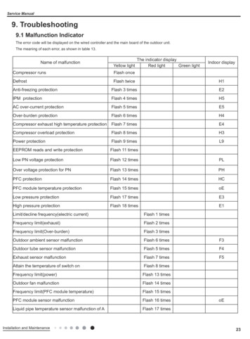
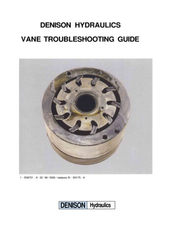
OPERATIONSeries 7500(0)/7600(0), 8500(0)/8600(0), 9500(0)/9600(0)Temperature Compensated, & Non-Temperature CompensatedMagnetic Pickup & AC Signal Generator Type Tachometer Sender InstrumentsSeries 7500(0)/7600(0), 8500(0)/8600(0), 9500(0)/9600(0) Diesel Multifunction Instruments use a microprocessor-based, non-volatileRandom Access Memory (RAM) to store engine hours and gallons of fuel consumed. Non-volatile RAM requires no power formemory retention.All “8”s are displayed for the first 3 seconds when the instrument is powered up. For 1 second after that, the instrument shows switchpositions and software version. After completing its start-up sequence, the instrument goes into normal operating mode.If supply voltage drops below 10V DC for any reason, the instrument displays a row of decimals across the bottom of the RPMwindow. This does not affect instrument accuracy. Stored engine hours and fuel consumption data will not be lost.Liquid crystal displays have an OPTIMUM VIEWING ANGLE. If your viewingangle is outside this range, contrast will decrease and numbers may flicker.Before drilling any holes in your dash, it’s a good idea to temporarily power upthe instrument ( 12V DC to the RED wire on plug #9, 12V DC to the BLACKwire on plug #5) before installing it and see if the intended viewing angle isacceptable.Engine HoursThe engine hours meter is shipped at or near zero hours. It accurately tracks thenumber of hours your engine has run. Unlike most hour meters, it onlyaccumulates time when the engine is actually running. If the meter is turned ON,but the engine is NOT running, NO time is added to the engine hour display.OptimumviewingangleThe engine hour meter cannot be reset.Tachometer (RPM)The Tachometer window shows engine speed in RPM and is accurate to within 1% (belt driven alternator tachometer signals areonly accurate to 50 RPM).Flow Consumption (GPH, LPH)The GPH/LPH window shows the rate at which your engine is consuming fuel. The GPH/LPH and Gallons/Liters readings will bothchange if the flow calibration switch (UPPER BLACK SWITCH) on the back of the instrument is turned.Totalizer (Gallons, Liters)The Gallons/Liters window shows total fuel consumed. The GPH/LPH and Gallons/Liters readings will both change if the flowcalibration switch (UPPER BLACK SWITCH) on the back of the instrument is turned.Totalizer ResetWhen the totalizer-reset switch is turned ON (Closed), the GALLONS/LITERS display will flash for ten seconds, then reset to zero.Flashing indicates the instrument is in reset mode. If the RESET switch is turned OFF (Opened), before the totalizer reads “0.0”, theinstrument will NOT reset. If you neglect to turn OFF the RESET switch, “0.0” continues to flash.08/21/08FloScan Instrument Company, Inc.3016 NE Blakeley Street, Seattle, WA 981057000-065-00GTel: (206) 524-6625Email: service@floscan.comFax: (206) 523-4961Http://www.floscan.com
AC Signal Generator, (G) Type Only750G/760G, 75TG/76TG, 750G0/760G0, 75TG0/76TG0850G/860G, 85TG/86TG, 850G0/860G0, 85TG0/86TG0950G/960G, 95TG/96TG, 950G0/960G0, 95TG0/96TG0Type “G” Diesel Multifunction Instruments are preset for the correct flow sensor combination. Before installing the instrument,verify that the switch settings are correct for your application. Flow Sensor types are coded as part of your kit model number.Recessed “Arrow” Rotary Switch SettingsSwitch Position01234567Flow SensorCAT 265/265RTY 265/201265/231231/231201/201BOS 231/201All 235/236 &233 B-C, C-D, D-E, E-F,and combinations233A/233ASwitch Position89ABCDEFFlow FCummins 231*Cummins 233C*Cummins 233D**Cummins Engines with PT pump injection system using one flow sensor in the feed line to the engine.08/21/08FloScan Instrument Company, Inc.3016 NE Blakeley Street, Seattle, WA 981057000-065-00GTel: (206) 524-6625Email: service@floscan.comFax: (206) 523-4961Http://www.floscan.com
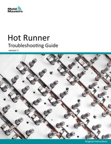
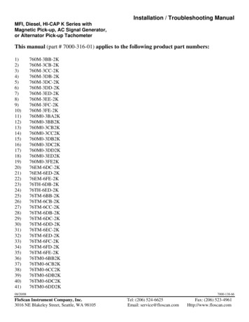
INSTALLATIONMECHANICAL & WIRING OVERVIEW – All G & FF Very High Flow Diesel SystemsTo Ensure System Accuracy, Follow All Installation Instructions. Sensor Placement. Determine where the Flow Sensor or Flow Sensor-Pulsation Damper assembly is to be installed. Install thesensor or sensor-pulsation damper assembly so that the ports marked IN and OUT. All orientation arrows, (Ï) must be pointingup. The forward sensor or forward sensor-pulsation damper assembly must be installed downstream of a Racor type primaryfilter. Upon exiting the return sensor, fuel must travel “Up-Hill” on its way back to the fuel tank. The fuel return line, between thereturn sensors’ outlet port and fuel tank should be no less than 12” and have a 1 to 2” upward rise. This keeps the return sensorflooded improving accuracy. Place sensor assemblies in a protected location away from water spray.Forward Sensor &Pulsation DamperAssemblyReturn Sensor &Pulsation FloScan233/236-2K233/236-2K*Caution: Diesel System Components are not designed for use on Gasoline Fuel Systems. Determine fitting type & size. Minimize the number of elbows and fittings. If swivel fittings are used, (JIC or SAE) their matingsurfaces must be sealed with FlareTite fitting seals. Fitting seals may be purchased through Fittings Inc. in Seattle, WA (206)767-4670, 1-800-552-0632, or a local hydraulic supply house.(Continued on next page) Select Instrument Mounting Location. The instruments’ face is waterproof and a gasket is provided to seal its bezel to thecontrol panel. Choose a location away from the compass. Install 65/6600 series instruments 12” away from compass. Choose ashaded location since direct sunlight may cause the LCD display to temporarily turn. This does not damage the LCD, but makes it08/11/09FloScan Instrument Company, Inc.3016 NE Blakeley Street, Seattle, WA 981054001-325-02ATel: (206) 524-6625Email: service@floscan.comFax: (206) 523-4961Http://www.floscan.com
impossible to read until cooling down. Make a cutout in the instrument panel for the instrument. The instruments’ maximumdepth is 3 ½” minus the thickness of the console panel.Instrument Series6500/66007500/7600, 8500/8600, 9500/9600, TwinScan Cutout Size3 1/16”33/8”Wiring. Determine wiring run length and the number of switches needed, (always use good quality marine grade switches). Use18 AWG conductors on runs under 50’. 16 AWG for runs over 50’. Run & Connect Wires. Wire one
and planning, your system will be installed with few problems. Todd Walker, Yacht Electric Co., (954) 325-9091 regularly installs FloScan Twin Diesel Systems in 16 to 20 hours. Difficult installations take him about 24. Vessel owners installing a FloScan Twin Diesel System for the first time may require an additional 4 to 10 hours.