Transcription
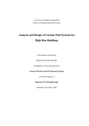
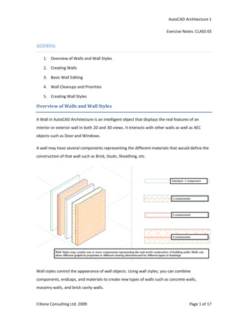
AutoCAD Architecture 1Exercise Notes: CLASS 03AGENDA:1. Overview of Walls and Wall Styles2. Creating Walls3. Basic Wall Editing4. Wall Cleanups and Priorities5. Creating Wall StylesOverview of Walls and Wall StylesA Wall in AutoCAD Architecture is an intelligent object that displays the real features of aninterior or exterior wall in both 2D and 3D views. It interacts with other walls as well as AECobjects such as Door and Windows.A wall may have several components representing the different materials that would define theconstruction of that wall such as Brick, Studs, Sheathing, etc.Wall styles control the appearance of wall objects. Using wall styles, you can combinecomponents, endcaps, and materials to create new types of walls such as concrete walls,masonry walls, and brick cavity walls. Xone Consulting Ltd. 2009Page 1 of 17
AutoCAD Architecture 1Exercise Notes: CLASS 03The display of a wall object depends on the direction from which you view the wall. In a planview, the wall object is displayed as parallel lines, as an architect would typically draw a wall. In3D view, the wall object is displayed, as it would appear in the real world, with surfaces showinglength, thickness, and height. You control what you want to display in each particular view byworking with the Display System.Creating WallsWalls may be created by selecting a Wall tool from the Tool Palette or the Build panel on theRibbon and then picking points in your drawing to specify the endpoints of each wall segment.As you pick points you will see your cursor and tracking lines appear along the Justification linefor the wall. Press the CTRL key while drawing a wall to Flip it or reverse the components.The justification for a wall can be set to Left, Right, Center, and Baseline from within theProperties Palette. While drawing the wall, you can also press the SHIFT key to cycle through theavailable justifications. The Baseline justification may be placed at some point within the extentsof the wall. This is useful for drawing walls along their main structure as for a foundation wallwith an attached footing extending beyond the width of the main wall.By selecting the Arc option of the wall command you can create curved walls defined by 3 pointson the arc. To create a curved wall with a specified radius, draw an arc along the desiredbaseline, and then convert the arc to a wall by selecting it, right clicking on a wall tool andchoosing Apply to / Linework from the context flyout. Curved walls can also be created by usingthe AutoCAD Fillet command and selecting two adjacent walls. Xone Consulting Ltd. 2009Page 2 of 17
AutoCAD Architecture 1Exercise Notes: CLASS 03The default multi-component walls defined in the existing ACA wall styles have been created insuch a fashion that specifying points in a clockwise direction, will ensure that exteriorcomponents will be drawn to the outside of the building. If you wish to draw the walls in acounterclockwise direction, press the CTRL key when you start drawing the wall segments and itwill Flip the wall construction, reversing the component layout.To check the wall direction for walls, look for an arrow-shaped grip that will always appear onthe exterior side of a selected wall. It you pick this grip; you can reverse the wall and change itsdirection. When Reversing a wall with the flip grip, by default it will maintain the dimensions andlocation of the wall. If you press CTRL while picking the Flip grip, the justification line will bemaintained at its current location and it will change the location of the wall. (unless the Baselineis also at the Center of the wall). Xone Consulting Ltd. 2009Page 3 of 17
AutoCAD Architecture 1Exercise Notes: CLASS 03Walls will automatically clean up with other walls if they belong to the same cleanup group andare at the same elevation.Single component walls may be created from Mass Elements in any 3D shape. Multi componentwalls can be modified in variety of ways including Plan modifiers, Body Modifiers, Sweeps,Interference Conditions, and Roof Line / Floor Line editing.When you add a door or window to a Wall, it will automatically add a hole to that wall. If youmove the door or window, the hole will move with it and if you delete the door or window, thehole in the wall will be deleted. When the wall is moved, the objects within the wall are movedas well and if you delete the wall, all objects contained within it will be deleted as well.To specify the defaultsettings and behaviour forcreating and editing Wallsand adding AECdimensions to walls, go tothe AEC Object SettingsTab of the Options dialogbox.To create a wall with User-specified settings, select a wall tool, open the Properties Palette andreview and make changes as required. If a value such as width is greyed out and you can’t pick itthis means that the value is preset in the Wall style.The Offset property is used to define points for the wall a specified distance away from thejustification line of the wall. This is useful for drawing walls with a centre justification but still beable to specify distances along one edge. If the offset is ½ the wall width, it will simulate a rightor left justification for the wall. Center justification for walls can aid in cleanup situations,especially for connecting or adjacent walls with very short segments.Roofline and Floorline offsets are used to extend components of the wall above the base heightor below the baseline elevation. Xone Consulting Ltd. 2009Page 4 of 17
AutoCAD Architecture 1Exercise Notes: CLASS 03Basic Wall EditingWalls can be edited a number of ways after they have been added. You can edit many of theproperties of a wall including its dimensions, its shape, and even its style from the PropertiesPalette. If any values are greyed out in the Properties palette they are defined in the wall style.Under General, straight wall segments may be converted to arc walls.Many more editing options are available from the context sensitive Wall tab on the Ribbon andright-click context menu when one or more walls are selected, as displayed in the image below.From the Wall tab or the cursor menu you can add all types of modifiers, change thejustification, define cleanup conditions, change the direction of the wall, join walls and createnew walls by Offsetting a selected wall. The Join Option allows you to combine contiguous, endconnected walls into one wall.The insert flyout on the Cursor menu and the General panel on the Ribbon allows you to add aDoor, Window, Opening, or Window Assembly to the selected wall. Add Selected, Select Similar,and the Object Viewer are other very useful tools found on the General panel and the cursormenu. Xone Consulting Ltd. 2009Page 5 of 17
AutoCAD Architecture 1Exercise Notes: CLASS 03Several editing options are also available by using Grip Edits which allow you to edit the BaseHeight, the heights at both ends of the wall, the length, the width, (if allowed by the style). If thewall is curved, you can also change the curve radius of the segment. The Location grip allows youto move a wall.Many standard AutoCAD editing commands may be applied to walls. You can Move, Copy,Offset, Mirror, Trim, Extend, Fillet, Chamfer, and Break walls exactly as you would ordinary lines.The Stretch command is very useful for editing AEC walls as it allows you to change the shapeand dimensions of walls, rooms, and even wings of buildings as easily as you would stretch arectangle.Although the standard offset command works with Walls, if you select the Offset option fromthe Wall Context Menu, it allows you to move an existing wall or copy the wall with an offsetdistance measured from the centre or the face of any of the wall's components. The WallContext Menu’s Offset command also allows you to adjust the position of a wall and align any ofits faces a certain distance away from a specified point. You might use this option ensure onewall is aligned with another wall. Xone Consulting Ltd. 2009Page 6 of 17
AutoCAD Architecture 1Exercise Notes: CLASS 03Wall Cleanups and PrioritiesYou can control how walls clean up with each other when they meet or cross through CleanupGroups, Cleanup Circles, Graphlines, and component prioritiesWall Graphlines define where intersecting walls will clean up. When you select a wall it willdisplay grips along its justification line. The Wall Graphline is drawn along the Justification line ofthe wall. All walls have a graphline which can be displayed by selecting the Diagnostic DisplayConfiguration.In the Diagnostic Display configuration, walls will be displayed as single line entities. If they havenon-zero cleanup radii, they will also display cleanup circles at the endpoints of each wallsegment. If you select a wall in the Diagnostic Display, you will see a triangular grip at the end ofeach wall that can be dragged to adjust the Cleanup Radius.You can also display the Wall Graphlines and Cleanup circles on top of the existing walls in theremaining Display Configurations by choosing Toggle Wall Graph Display from the Cleanupsflyout in the Walls context menu. When you are displaying the Wall Graph along with your wallsyou are able to grip edit the cleanup circles .Walls belonging to the same Cleanup Group will clean up when their Graphlines intersectcleanly, when the cleanup circle of one wall touches the other wall’s graphline, or when thecleanup circle of one wall overlaps the centre point of the other walls cleanup circle. Xone Consulting Ltd. 2009Page 7 of 17
AutoCAD Architecture 1Exercise Notes: CLASS 03To keep walls from cleaning up, you can set the "Cleanup Automatically" property to No for oneof the selected walls. A second option is to create a new cleanup group in the style manager andassign it to one of the sets of walls with the Properties Palette.Walls with multiple components will cleanup with other walls based on the cleanup priorities oftheir components. A cleanup priority is an index number assigned to all components in a WallStyle. The lower the priority index number, the more powerful the component is. A concretemasonry wall with a priority of 200 easily cuts through a stud wall with a priority of 500 and itsGWB covering with a priority of 1200.Ensure that all walls are at the same elevation. Check the Z-Value under location in theProperties Palette to verify a set of walls share the same elevation.The Cleanup Panel on the Wall tab of the Ribbon allows you to apply L Cleanups and T Cleanupswhich will trim and extend walls automatically to make them cleanup. It is usually easierhowever to use the Trim, Extend and Fillet commands to create these cleanups and maintainbetter control over which walls will be retained and which portions will be removed.The Edit in Place option on the Cleanup panel allows you to create custom cleanup conditionsand override the default priorities for one or more selected components at a wall intersection. Xone Consulting Ltd. 2009Page 8 of 17
AutoCAD Architecture 1Exercise Notes: CLASS 03If Wall cleanups fail, the walls will sometimes display triangular warning symbols called Defectmarkers and often stop showing properly in 3D views. If you see Defect Markers appear youshould examine the wall’s Graphlines and try to fix the problem before proceeding. If you floatyour cursor over the defect marker, a tooltip will appearThe Majority of Cleanup problems seem to occur when care is not taken to draw neatly andensure that wall segment endpoints align with each other precisely. Small openings or overlapscan often lead to defect markers. Using the Autosnap settings in the AEC options can aid greatlyin ensuring your Graphlines meet precisely.Use a Zero cleanup radius wherever possible and only use clean up circles when it is impossibleto make the Graphlines touch. Use the smallest cleanup radius that will allow you to reach thetarget graphline. Large, overlapping cleanup circles can cause walls to display defect markers andeven disappear as they clean themselves out of existence!If you need to draw very short wall segments with tight jogs, use a centre justification. Xone Consulting Ltd. 2009Page 9 of 17
AutoCAD Architecture 1Exercise Notes: CLASS 03Creating Wall StylesWall styles may be created from scratch in the Style Manager or you can create a wall style bycopying an existing style, assigning a new name to the copied style and then modifying theproperties as required.The Wall components and their properties define the main structure of the wall. Eachcomponent corresponds to a defining section of the wall such as brick, insulation, and framebackup walls. Spaces such as air gaps must be included as well as placeholder components forelements that may be swept along the wall such as a baseboard.Wall components are rectangular volumes with their dimensions in section defined by a width, ahorizontal offset from a baseline, and vertical offsets from the Wall bottom, Wall top, Wall BaseHeight, or Wall Baseline.Wall components may be modified or created in the Components tab of the Wall Style dialogbox. The Wall styles Component browser on the right allows you to drag and drop componentsfrom other styles in your drawing ensuring that components with the same name have the samecleanup priority.The component browser also allows you to open one of ACA's main wall style drawings and thendrag and drop predefined components into your new wall style. This method ensures that all ofyour components will follow the ACA wall component Priority Index. Xone Consulting Ltd. 2009Page 10 of 17
AutoCAD Architecture 1Exercise Notes: CLASS 03If you create components from scratch make sure you are setting the priority values toaccommodate cleanups with other walls. Refer to the component priority index shown on thelast page of the notes for this lesson or in the help file to make your custom components followthe priorities in the ACA Priority index.Components are defined with a width and edge offset from an imaginary
AutoCAD Architecture 1 Exercise Notes: CLASS 03 Xone Consulting Ltd. 2009 Page 8 of 17 To keep walls from cleaning up, you can set the "Cleanup Automatically" property to No for one of the selected walls. A second option is to create a new cleanup group in the style manager and assign it to one of the sets of walls with the Properties Palette. Walls with multiple components will cleanup with .