Transcription
Department of Civil and Construction EngineeringSoil MechanicsLaboratory Manual2017 - 2018Engr. Rana Muhammad Sajid
Soil MechanicChapter-1 LABORATOY MANUALMOISTURE CONTENT . . .3Moisture Content Determination by Oven drying method . . . .3Moisture Content Determination by Speedy moisture meter . . .7Chapter-2 SPECIFIC GRAVITY . .10 Specific Gravity Determination . . 10Chapter-3 GRAIN SIZE ANALYSIS. . . 14 Sieve Analysis . .14Hydrometer Analysis . .19Chapter-4 ATTERBERG LIMITS 25 Liquid Limit Test . 26Plastic Limit Test . .27Chapter-5 FIELD DETERMINATION OF DENSITY . 30 Core Cutter Method 30Sand Replacement Method . 33Chapter-6 COMPACTION 37 Standard AASHTO Method . 37Modified AASHTO Method . 41Chapter-7 PERMEABILITY .45 Constant Head Permeameter 47Variable Head Permeameter . 49Chapter-8 TRIAXIAL TEST . . 51 Triaxial test . . 51Chapter-9 CONSOILIDATION TEST 55 Consolidation Test .552
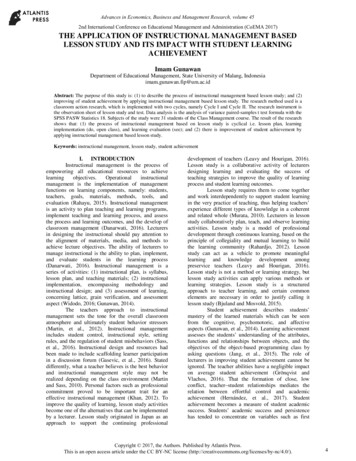
LABORATOY MANUALSoil MechanicChapter-1MOISTURE CONTENTMoisture Content Determination by OvenDrying MethodObjectiveTo determine the amount of water or moisture present in the given quantity of soil in terms of its dryweight.Need and Scope of the ExperimentIn almost all soil tests natural moisture content of the soil is to be determined. The knowledge of themoisture content is essential in all studies of soil mechanics. To sight a few, natural moisture content isused in determining the bearing capacity and settlement. The natural moisture content will give an ideaof the state of soil in the field.TheoryWater content or moisture content determination is a routine laboratory test, the results of which areused in evaluation of different important engineering properties of soil. The determination of moisturecontent involves removing of soil moisture by oven-drying a soil sample until the weight remainsconstant. The moisture content is expressed in percentage and is calculated from the sample weightbefore and after drying.Mathematically it can be written as;ω 𝑊𝑤𝑊𝑠𝑋100Ww Weight of soil waterWs Weight of soil solidsApparatus1. Moisture tins2. Weighing balance (Least count of 0.01 g)3. Drying oven (Temperature control at 110 5 0C)Procedure1. Take empty clean moisture tin and mark it with an identifying number or code Fig. 1.1.2. Weight the container and record the weight as W1 to the nearest 0.01 g3
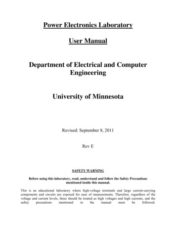
Soil MechanicLABORATOY MANUAL3. Take representative wet soil sample (not less than 20 g) and place it quickly in the moisture tin4. Weight the moisture tin with wet soil sample to the nearest 0.01 g and record this weight as W25. Place the moisture tin with the wet soil sample in drying oven, Fig 1.2 at constant temperatureof 110 50 C for 24 hours.6. After 24 hours remove the moisture tin from drying oven and weight it to the nearest 0.01 g.Record this weight as W3Fig 1.1: Weighing balance, Moisture tins, Gloves and Spatula4
LABORATOY MANUALSoil MechanicFig 1.2: Drying oven (Temperature control at 110 5 C)Precautions1. If it is not possible to place the container carrying wet soil sample in drying oven immediately,cover the container with led2. If it is suspected that gypsum is present in the soil, the soil sample should not be subjected to atemperature beyond 600C. Otherwise gypsum will lose its water of crystallization affectingthereby the results of moisture content. Oven drying at 600C may, however, be continued forlonger time in order to ensure complete evaporation of free water present in the sample.Observations and Calculationsω 𝑊𝑤𝑊𝑠𝑋100 W2 W3XW3 W1100Where;W1 Weight of tin (g)W2 Weight of moist soil tin (g)W3 Weight of dried soil tin (g)5
Soil MechanicLABORATOY MANUALCan No.Wt. of wet soil can (g) W2Wt. of dry soil can (g) W3Wt. of can (g) W1Wt. of dry soil (g)Wt. of moisture (g)Water content (%)Depth (m)Moisture Content, ω ReferenceASTM D2216-98Standard test method for laboratory determination of water (moisture) content of soil and rock by mass.Comments6
LABORATOY MANUALSoil MechanicMoisture Content Determination bySpeedy Moisture MeterObjectiveTo determine the moisture content of a soil sample by speedy moisture meter.TheoryThe speedy moisture meter provides a quick, simple means of determining the moisture content of soil.It is particularly useful for field determination of moisture contents in conjunction with the fieldcompacting testing. The speedy moisture meter is also known as calcium carbide gas moisture tester.The basic principle behind this method is that the free moisture in the soil reacts with calcium carbidereagent to form a gas called acetylene gas eq.1. This gas exerts a pressure on the internal side of thewalls of speedy moisture meter which is reflected by a pressure dial. The pressure dial is calibrated insuch a way that pressure reading reflects the percent moisture by wet weight of soil directly.The reaction which takes place inside the speedy moisture meter is as follows; CaO C2H2 --------- (1)CaC2 H2OSince the moisture content by definition is expressed as a percentage of dry weight of soil, eq. 2.Readings obtained by speedy moisture meter are corrected using following expression;ω𝑠𝑝ω 1 ω x 100 --------------------- (2)𝑠𝑝whereω Moisture content in percentage of dry weight of soilωsp Moisture content as obtained by speedy moisture meter expressed as decimal fractionApparatus1.2.3.4.5.Speedy moisture meterCalcium carbide reagentTwo 1.25 inch steel ballsCleaning brush and clothScope for measuring calcium carbide reagent7
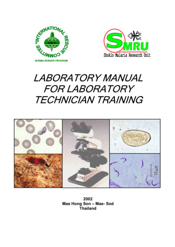
Soil MechanicLABORATOY MANUALProcedure1. Weight approximately 6 g of wet soil sample on the tarred scale, and place it in the cap of thetester2. Place three scoops of calcium carbide and two inch steel balls in the large chamber of themoisture tester Fig. 1.33. With the pressure vessel in an approximate horizontal position, insert the cap in the pressurevessel and seal it by tightening the clamp4. Raise the moisture tester to a vertical position so that the soil in the cap falls into the pressurevessel5. Shake the instrument vigorously so that all lumps are broken up to permit the calcium carbide toreact with all available free moisture. The instrument should be shaken with a rotating motionso that the steel balls do not damage the instrument or cause soil particles to becomeembedded in the orifice leading to pressure diaphragm6. When the needle stops moving, record the dial reading while holding the instrument in ahorizontal position at eye level.7. With the cap of the instrument pointed away from the operator, slowly release the gaspressure. Empty the pressure vessel and examine the material for lumps. If the sample is notcompletely pulverized, the test should be repeated using a new wet soil sample.8. Apply correction to the dial reading to convert the moisture content in terms of dry weight ofsoilFig 1.3: Speedy moisture meterLimitationThe speedy moisture meter can determine the moisture content only up to 20 percent. If the moisturecontent of the sample exceeds the limit of the pressure gauge, one half size samples must be used anddial gauge reading must be doubled.8
LABORATOY MANUALSoil MechanicPrecautions1. Care should be taken that no calcium carbide comes in contact with the soil until a completeseal is achieved2. Shake the instrument by rotating the instrument in horizontal plane so that moisture tester isnot damaged during shaking3. After completion of test, slowly release the gas pressure pointing the instrument away fromoperatorObservations and Calculationsω𝑠𝑝ω 1 ω x 100𝑠𝑝Moisture Content, ω Sample no.ω𝑠𝑝ωComments9
Soil MechanicChapter-2LABORATOY MANUALSPECIFIC GRAVITYSpecific Gravity DeterminationObjectiveTo familiarize the students with general method of obtaining the specific gravity of a mass of any type ormaterial composed of small particles (especially soil)TheoryA value of specific gravity is necessary to compute the void ratio of a soil, it is used in the hydrometeranalysis, and it is useful to predict the unit weight of a soil. Occasionally, the specific gravity may beuseful in soil mineral classification; e.g., iron minerals have large value of specific gravity than silica’s.The specific gravity of any substance is defined as the unit weight of the material divided by the unitweight of distilled water at 40C. Thus specific gravity of soil can be found as;𝐺𝑠 𝛾𝑠𝑜𝑖𝑙𝛾𝑤𝑎𝑡𝑒𝑟As long as equal volume of water and soil are involved, the above stated form can be simplified as;𝑊𝑠𝑜𝑖𝑙 𝑉𝐺𝑠 𝑊𝑤𝑎𝑡𝑒𝑟 𝑉Strictly speaking above mentioned equation is only valid if we do not consider any density change withtemperature. However, a slight increase in precision to account for temperature effects on the densityof water can be obtained by rewriting above stated equation as;𝐺𝑠 𝑊𝑠𝑜𝑖𝑙 𝛼𝑊𝑤𝑎𝑡𝑒𝑟Where α is the ratio of the unit weight of water at temperature T of the test and at 40. The value of Gsobtained at temperature T (which will be too large if T 40C) is appropriately reduced.α 𝛾𝑇𝛾40𝐶10
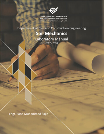
Soil MechanicLABORATOY MANUALApparatus1.2.3.4.5.6.7.PycnometerWeighing balance (Least count of 0.01 g)ThermometerHot plate or Bunsen burnerFunnelDrying ovenPaper towelProcedure1. Weigh the dry pycnometer to nearest 0.01 g and record it as W12. Take about 100 g of oven dried soil and put it into the flask. Weigh the flask and dry soil to thenearest 0.01 g. Record this weight as W23. Add water in the Pycnometer, Fig. 2.1 until it is about two-third full. In order to remove theentrapped air from soil and water, heat the mixture at least 2h after soil –water mixture comesto a full boil. Use only enough heat to keep the slurry boiling. Agitate the slurry as necessary toprevent any soil from sticking to or drying on to the glass above the slurry surface4. Allow the mixture to cool, and then fill the flask with distilled water to above the calibrationmark5. Place the stopper in the bottle while removing the excess water. Be sure the entire exterior ofthe flask is dry. Weigh the flask to the nearest 0.01 g and record this weight as W36. Empty the flask, wash it thoroughly and fill it completely with water. Dry the exterior of theflask. Weigh the flask and record it as W47. Repeat the procedure three times8. Record the temperature of soil water mixture11
Soil MechanicLABORATOY MANUALFig 2.1: Pycnometer and Weighing balance𝑮𝒔 (𝑾𝟐 𝑾𝟏 )𝜶[(𝑾𝟒 𝑾𝟏 ) (𝑾𝟑 𝑾𝟐 )]Precautions1. Make sure no air is entrapped within the soil water mixture2. Weights should be obtained from a properly balanced weighing scaleObservations and CalculationsTest no.123Volume of flaskW1 (g)W2 (g)W3 (g)W4 (g)α (Table 1)Gs12
Soil MechanicLABORATOY MANUALTable 1. Typical values of correction factor, α;T (0C)Correction Factor, eferenceASTM D854-02Standard test method for specific gravity of soil solids by water pycnometerComments13
Soil MechanicLABORATOY MANUALChapter- 3 GRAIN SIZE ANALYSISParticle Size Analysis (Mechanical Analysis)ObjectiveTo introduce the students to the method of making a mechanical grain size analysis of a soil andpresenting the resulting dataTheoryGrain size analysis is very important in the determination of engineering properties of soil e.g. suitabilitycriteria of soils (for road, airfield, levee, dam and foundation material), soil water movement,susceptibility to frost action etc.The grain size analysis is the attempt to determine the relative proportions of the different grain sizeswhich make up soil mass. For this, sample should be statically representative of the soil mass.By carrying out mechanical analysis, particle sizes and their relative distribution can be done for theparticle greater than 0.075 mm. the mechanical analysis is carried out by stacking the sieves, one on topof the other, pouring a known weight of soil into the top sieve on the stack, and shaking the sieve in acertain manner to allow the soil to fall down through the stack.The stack of sieves is known as nest of sieves. The nest is arranged with the largest screen openings(smallest sieve number) on top, progressing to the sieve with the smallest screen opening (largest sievenumber) on the bottom of the nest. A lid is placed on the top of the nest and pan is placed below thebottom sieve to catch any soil that passes through the smallest opening. The number or size of thesieves used in the nest depends on the type of the soil and the distribution of the particle sizes.Generally sieve No. 4, 10, 40, 100, 200 are used for classifying the soil.Apparatus1.2.3.4.A set of sievesMechanical soil pulverizerWeighing balance (least count 0.01 g)Mechanical sieve shakerProcedure1. Obtain 500 g of soil sample which has already been pulverized by placing it on sieve no. 200 andthen oven dried2. Arrange a nest of sieves including sieves no. 4, 10, 40, 100, 200, Fig. 3.1.3. Place the set of sieves in the mechanical sieve shaker and sieve it for 5 to 10 mint. Note that ifthe entire set of sieves does not fit into the shaker perform a hand shaking operation until the14
LABORATOY MANUALSoil Mechanictop few sieves can be removed from the stack and then place the remainder of the stack in themechanical shaker4. Remove the nest of sieves from the shaker and obtained the weight of the material retained oneach sieve. Sum these weights and compare with the actual weight taken. A loss of more than 2% by the weight of the residual material is considered unsatisfactory and the test should bereplaced5. Compute the % retained on each sieve by dividing the weight retained on each sieve by theoriginal sample weight6. Compute the % passing by starting with 100 % and subtracting the cumulative % retained forthat sieveFig 3.1: Set of sieves and mechanical sieve shakerObservations and CalculationsWeight of sample (g)Sieve No.Diameter(mm)Weight of SoilRetained (g)% WeightRetained1234CumulativePercentRetained (%)5PercentPassing (%)615
Soil MechanicLABORATOY MANUALColum (5) Colum (4) Colum (5) of previous lineColum (4) (Colum (3)/ Total Weigh) 100Colum (6) 100 - Colum (5)D10 D30 D60 𝐶𝑐 𝐷60 𝐷10(𝑫𝟑𝟎 )𝟐𝑪𝒄 (𝑫𝟏𝟎 ) (𝑫𝟔𝟎 )16
Soil MechanicLABORATOY MANUAL17
Soil MechanicLABORATOY MANUALPrecautions1) Particles that appear to be stuck in the sieve screen should never be forced on through the mesh.There are two reasons for not doing this The particles would have passed the screen on their own had they been smaller than themesh opening. Forcing these particles through the screen to be retained on the next sizewould distort the grain size results Secondly forcing the particles through the mesh can damage the screen and necessitate itsreplacementParticles caught in the screen should be removed by brushing with the proper sieve brush. Brushingshould be done from the undesired of the screen in order that the particles can be brushed out of thescreen in the direction from which it entered in the screen opening. Stubborn (obstinate) particles thatcannot be removed by rushing should be left in place.2) Lumps of soil must have broken down into their individual particles in order for the grain sizeanalysis to be valid. This is accomplished in two ways. The first is to break up lumps with a rubbertipped pestle in ceramic mortar. It has been found that the rubber-tipped pestles will not grind orcrush the individual particles while a ceramic or metal-tipped pestle will. The second is to wet-sievethe soil. Washing the particles that are retained on the No.200 sieve with water and this willaccomplish two things. It separates those small lumps that might not have been broken up with the rubber tippedpestle into individual particles It washes the “Dust Size” particles and through the No.200 sieve3) A 10 minute shaking period is suggested in procedure. A large sample is requires longer shaking.Similarly a sample comprising primarily of fine grained material will require a longer shaking periodthan a coarse grained sample of equal weightReferenceASTM D22Standard test method for particle-size analysis of soilsComments18
Soil MechanicLABORATOY MANUALParticle Size Analysis (Hydrometer Analysis)ObjectiveThe hydrometer method is used to approximate the particle size distribution for particles that passessieve No.200. The hydrometer test is held as an extension to the sieve analysis to make us able toclassify the soil.Apparatus1.2.3.4.Sedimentation cylinder (1,000 cu-cm cylinder) also termed a hydrometer jarHydrometer (152H)Soil-dispersion device (malt mixer)Dispersion agent (sodium hexametaphosphate NaPO3), trade name calgon, or sodiumsilicate (Na 2Sio 3) also called water glass5. thermometerProcedure1. Take the fine soil from the bottom pan of the sieve set, place it into a beaker, and add 125 mL ofthe dispersing agent (sodium hexametaphosphate (40 g/L)) solution. Stir the mixture until thesoil is thoroughly wet. Let the soil soak for at least ten minutes.2. While the soil is soaking, add 125mL of dispersing agent into the control cylinder and fill it withdistilled water to the mark. Take the reading at the top of the meniscus formed by thehydrometer stem and the control solution. A reading less than zero is recorded as a negative (-)correction and a reading between zero and sixty is recorded as a positive ( ) correction. Thisreading is called the zero correction. The meniscus correction is the difference between the topof the meniscus and the level of the solution in the control jar (Usually about 1). Shake thecontrol cylinder in such a way that the contents are mixed thoroughly. Insert the hydrometerand thermometer into the control cylinder and note the zero correction and temperaturerespectively.3. Transfer the soil slurry into a mixer by adding more distilled water, if necessary, until mixing cupis at least half full. Then mix the solution for a period of two minutes.4. Immediately transfer the soil slurry into the empty sedimentation cylinder. Add distilled waterup to the mark.5. Cover the open end of the cylinder with a stopper and secure it with the palm of your hand.Then turn the cylinder upside down and back upright for a period of one minute. (The cylindershould be inverted approximately 30 times during the minute.)6. Set the cylinder down and record the time. Remove the stopper from the cylinder. After anelapsed time of one minute and forty seconds, very slowly and carefully insert the hydrometerfor the first reading. (Note: It should take about ten seconds to insert or remove the hydrometerto minimize any disturbance, and the release of the hydrometer should be made as close to thereading depth as possible to avoid excessive bobbing).7. The reading is taken by observing the top of the meniscus formed by the suspension and thehydrometer stem. The hydrometer is removed slowly and placed back into the control cylinder.Very gently spin it in control cylinder to remove any particles that may have adhered.8. Take hydrometer readings after elapsed time of 2 and 5, 8, 15, 30, 60minutes and 24 hour19
Soil MechanicLABORATOY MANUALHydrometer Analysis1. Apply meniscus correction to the actual hydrometer reading2. From Table 1, obtain the effective hydrometer depth L in cm (for meniscus corrected reading)3. For known Gs of the soil (if not known, assume 2.65 for this purpose), obtain the value of K fromTable 24. Calculate the equivalent particle diameter by using the following formula:𝐷 𝐾 5.6.7.8.𝐿𝑡Where t is in minutes, and D is given in mm.Determine the temperature correction CT from Table 3.Determine correction factor “a” from Table 4 using Gs.Observations and Calculations Calculate corrected hydrometer reading as follows:Rc RACTUAL - zero correction CTCalculate percent finer as follows:𝑃𝐴 𝑅𝑐 𝑎 100𝑊𝑠Where WS is the weight of the soil sample (g)9. Adjusted percent fines as follows:𝑃𝐴 𝐹200 𝑃100F200 % finer of #200 sieve as a percent10. Plot the grain size curve D versus the adjusted percent finer on the semi logarithmic sheet.20
Soil MechanicLABORATOY MANUALTable 1.Values of Effective Depth Based on Hydrometer and Sedimentation Cylinder of Specific Sizes21
Soil MechanicLABORATOY MANUALTable 2.Values of k for Use in Equation for Computing Diameter of Particle in Hydrometer AnalysisTable 3.Temperature Correction Factors torCT1.10-0.90-0.70-0.50-0.300.00 0.20 0.40 0.70 1.00 1.30 1.65 2.00 2.50 3.05 3.8022
LABORATOY MANUALSoil MechanicTable 4 Correction Factors a for Unit Weight of SolidsUnit Weight of ydrometer AnalysisObservation and CalculationsTest Date:Tested By:Hydrometer Number (if known):Specific Gravity of Solids:Dispersing Agent:Weight of Soil Sample: (g)Zero Correction:Meniscus Correction:23
Soil MechanicLABORATOY MANUALObservations and CalculationsDateTimeElapsed Time (min)Temp. (OC)Actual Hydro. Rdg.RaHyd. Corr. forMeniscusL from Table 1K from Table 2D (mm)CT from Table 3a from Table 4a from Table 4% Finer P% Adjusted FinerPAPrecautions1. It is usual to leave the hydrometer in the soil suspension for the first 4 min. remove it andreinsert it each time for all additional readings. Little error will be caused if the hydrometer isleft in the jar for all 4 of the readings as compensating errors of the fluid disturbance will tend tooffset errors due to soil participating on the hydrometer bulb.2. When placing the hydrometer in the soil suspension for a reading proceed slowly enough that ittakes about 10 sec. for the operation (the insertion time should not exceed approximately 5 to 6second)3. Consistent readings indicate a uniform mixture of soil water suspension4. Time beyond first 2 hr. of readings are approximate and are set to give reasonable spread ofplotted points for the percent finer vs grain size (diameter) curveReferenceASTM D422Standard test method for particle-size analysis of soilsComments24
Soil MechanicChapter-4LABORATOY MANUALATTERBERG LIMITSDetermination Atterberg’s Limits(Liquid Limit and Plastic Limit)ObjectiveTo introduce the students to the procedure for determining the liquid and plastic limitTheoryThe liquid and plastic limits are two of the five “limits” proposed by A. Atterberg, a Swedish agriculturalscientist. These limits are;1. Cohesion Limit – that moisture content at which soil crumbs just stick together2. Sticky Limit – that moisture content at which soil just sticks to a metal surface such as spatulablade. This would have some significance to the agricultural engineer since it is related to soilsticking to the moldboard of a plow or disc in cultivating soil3. Shrinkage Limit – that moisture content below which no further soil volume reduction(shrinkage) occurs4. Plastic Limit – moisture content below which soil is non-plastic5. Liquid Limit – moisture content below which the soil behaves as plastic material. At thismoisture content, the soil is on the verge of becoming a viscous fluidThe liquid and plastic limits have been widely used all over the world, primarily for soil identification andclassification. The shrinkage limit is useful in certain geographical areas where soil undergo large volumechanges when going through wet and dry cycles. The cohesion and sticky limits are used very littleworldwide.Apparatus1. Liquid limit device with Casagrande grooving tool (cuts a groove of size 2 mm wide at thebottom, 11 mm wide at the top and 8 mm high)2. No.40 ASTM sieve3. Water content equipment4. Spatula5. Glass plate6. 1/8 inch diameter brass rod7. containers25
Soil MechanicLABORATOY MANUALProcedure for Liquid Limit Determination1. Pulverize a sufficient quantity of air-dried soil to obtain about 250 g of representative samplepassing through No.40 sieve2. Adjust the height of fall of the liquid limit device to exactly 1 cm. Use the 1 cm calibration blockat the end of the grooving tool for making this adjustment3. Place about 250 g of soil in a glass plate, (or container). Add distilled water very slowly and usingspatula mix the soil thoroughly until it becomes a thick, homogeneous paste. Be careful not toadd too much water. Add approximately that much water in the soil to make it such consistentthat a blow count of 30 to 40 blows to close the standard groove of ½ inch is obtained.4. Place a portion of the soil paste in the brass cup, Fig. 4.1, of liquid limit device and by means ofspatula, level and smooth the surface of soil.5. Cut a clean, straight groove in the soil by drawing the grooving tool along the diameter throughcenter of the hinge which separates the soil into two parts.6. Turn the crank of the liquid limit device at the rate of two revolutions per second and count thenumber of blows (drops) until two parts of the soil come into contact at the bottom of thegroove along a distance ½ inch.7. Take about 20-40 g of sample of soil from the closed part of the groove for subsequent watercontent determination and put it in a pre-weighted moisture content container. Remove theremaining soil from the brass cup and return it to the container. Wash and dry the cup.8. Repeat steps 4, 5, 6 and 7 at least four times using the same soil samples to which further smallincrements of distilled water have been added. The amount of water added must be such thatthe blows (drops) count range between 10 and 509. The test should always proceed from the drier to the wetter conditions. If it should occur thattoo much water was added to the soil must never be dried by adding additional dry soil. Theproper procedure is to thinly spread the wet soil on the glass plate and let it air dry to thedesired consistency. Continuous mixing and fanning of wet soil is permitted to expedite thedrying process10. Weight the moisture containers and place them in the oven to dry overnight11. The U.S army Corps of Engineers found from an investigation conducted with 767 liquid limitdeterminations that the liquid limit of soil could be reliably obtained by conducting only one trialand using the following correlation equation;𝐿. 𝐿 𝑊𝑛 (𝑁/25) 0.121N Number of blows required to close the standard groove for distance of ½ inchWn moisture content of the soil which closed after N blows26
Soil MechanicLABORATOY MANUALFig 4.1: Casagrande apparatusObservations and CalculationsCan No.1234Wt. of wet soil can (g)Wt. of dry soil can (g)Wt. of can (g)Wt. of dry soil (g)Wt. of moisture (g)Water content %No. of blowsProcedure for Plastic Limit Determination1. Take about 20 g of air dried soil from the thoroughly mixed portion of the material passingNo.40 sieve. Mix it on the glass plate with sufficient distilled water to make it plastic enough tobe shaped into a ball. Leave the plastic soil mass for some time to mature2. Take about 8 g of the plastic soil, make a ball of it, and roll it between the fingers and glass platewith just sufficient pressure to roll the mass into a thread of uniform diameter throughout itslength, Fig. 4.2. When the diameter of the thread has decreased to 1/8 inch. The specimen iskneaded together and rolled out again. Continue the process until the thread just crumbled at1/8 inch diameter, Fig. 4.3.3. Collect the crumbled soil thread in the container for water content determination27
Soil MechanicLABORATOY MANUAL4. Repeat the test for three to four times and take average value of these readingsFig 4.2: Spatula, glass plate cans and ellipsoidal soil sampleFig 4.3: Plastic Limit Determination28
Soil MechanicLABORATOY MANUALObservations and CalculationsCan No.1234Wt. of wet soil can (g)Wt. of dry soil can (g)Wt. of can (g)Wt. of dry soil (g)Wt. of moisture (g)Water content %PrecautionsMake sure that the liquid limit test should always proceed from the drier to the wetter conditions.Otherwise, drying of soil sample may cause wastage of time.ReferenceASTM D4318Standard test method for liquid limit, plastic limit and plasticity index of soils.Comments29
Soil MechanicLABORATOY MANUALChapter-5FIELD DETERMINATION OF DENSITYCore-Cutter MethodObjectiveCore cutter is used for finding field density of cohesive/clayey soils placed as fill. It is a rapid methodconducted in the field. It cannot be applied to coarse grained soil as the penetration of core cutterbecomes difficult due to increased resistance at the tip of core cutter leading to damage to core cutterApparatus1. Cylindrical core cutter of seamless steep tube, 130 mm long and 10 cm internal diameter withwall thickness of 3mm, beveled at one end; giving a volume of 1000 cm3.2. Steel dolly, 2.5 cm high and 10 cm internal diameter with wall thickness of 7.5 mm with a lip toenable it to be fitted on top of the core cutter.3. Steel rammer with solid mild steel foot 14 cm diameter and 7.5 cm height with a concentricallyscrewed 2.5 cm diameter solid mild steel staff.4. Balance5. Palette knife having blade approximately 20 cm long and 3 cm wide.6. Steel ruler.7. Container for determination of water contentProcedure1. Calculate internal volume of the core cutter.2. Weigh the empty core cutter and record its weight.3. Apply oil on inner surface of the core cutter.4. Place the core cutter on a freshly prepared plain ground with dolly on it; and gently hammer it sothat the cutter will get pushed in the
In almost all soil tests natural moisture content of the soil is to be determined. The knowledge of the moisture content is essential in all studies of soil mechanics. To sight a few, natural moisture content is used in determining the bearing capacity and settlement. The natural moisture con