Transcription
On-LineCardioTheater Instruction Manual forAmplifier Models 800 and 1600 (wired)Full installation instructions accompany your Cardio Theater equipment order. This On-Line version of ourInstallation/Instruction Manual is included in our web site for your convenience. If you have any questionsregarding your installation that are not covered by this Manual or by our Troubleshooting Guide, pleasecontact our Service Department:Cardio Theater Inc.Service DepartmentTelephone: 1-800-776-6695E-mail: service@cardiotheater.comTable of Contents(Click to jump to the page you want to see.)Before you beginImportant SafeguardsSuggestions for InstallationInstallation: Controls and IndicatorsInstallation: System ConnectionsInstallation: Attaching Upper Monitors
Setup and Operation: Input Signal SetupSetup and Operation: Upper Monitor OperationSpecificationsBefore You BeginPlease insure that you have all of the required equipment beforedisposing of any packing materials.Equipment List:Model 800 or 1600 AmplifierUpper Monitors,quantity as orderedPower Cord,quantity (1)Floor Monitors,quantity equal to Uppers
Plastic wire ties;(4) for each Upper MonitorTerminators,(2) with Model 800 Amp or(4) with Model 1600 Amp"T" Connectors;(1) for each Floor MonitorCoiled Cables;(1) for each Upper MonitorBNC Bullet Connectors;(2) with Model 800 Amp or(4) with Model 1600 AmpCoax Cable;(1) for each Floor MonitorClick here to go back to the Index.Important SafeguardsPlease read all of these safeguards before operating the unit. Follow all warnings placed on the unit and adhere to theoperating and use instructions. Retain your manual for future reference.1. Power sources - Connect the unit to a power source onlyof the type described in the operating instructions or asmarked on the appliance.2. Power cord protection - Route all power-supplycords so that they are not walked on or pinched by itemsplaced upon or againstthem.
3. Grounding - Take precautions so that the grounding orpolarization means of the unit are not defeated.4. Ventilation - Position the unit so that its locationdoes not interfere with ventilation. To maintain goodventilation, do not put items on or over the unit. Do notuse the unit on a cushioned surface that may block theventilation openings.5. Water and moisture - Do not locate the unit near6. Temperature - The unit may not function properly ifused at extreme temperatures. The ideal temperature is41oF (5oC) to 87oF (30oC)water.7. Heat - The unit should be located away from heat sourcessuch as radiators, heat registers, stoves, etc.8. Electric shock - Care should be taken so that objectsdo not fall and liquid is not spilled on the enclosure. If ametal object, such as a hairpin or a needle, comes incontact with the inside of this unit, a dangerous electricshock may result.9. Enclosure removal - Never open the enclosure. If theinternal parts are accidentally touched, a serious shock mayoccur.10. Cleaning - Do not use solvents such as alcohol;paint thinner, etc. to clean the unit. Use a clean dry cloth.
11. Abnormal smell - If an abnormal smell is detected,immediately turn the power OFF and disconnect the powercord. Contact your dealer or service center.12. Stands - Any component should be moved withcare. Quick or excessive force could cause the stand tooverturn.13. Nonuse periods - The power cord should bedisconnected when left unused for a long period of time.14. Damage requiring service - The unit should beserviced by a qualified technician when:A. The power supply cord or the plug has been damaged;B. Objects have fallen, or liquid has been spilled into theunit;C. The unit has been exposed to rain;D. The unit does not appear to operate normally orexhibits a marked change in performance; orE. The unit has been dropped, or the enclosure damaged.15. Servicing - The user should not attempt to service theunit beyond that described in this manual. All other servicingshould be referred to a qualified technician.Safety PrecautionsWARNING: To prevent fire or electric shock, do not expose this appliance torain or moisture.Caution: If you see this symbol,be aware of its meaning: Toreduce the risk of electric shock,do not remove the cover or backof the unit. No user-serviceableparts are inside. Refer servicingto a qualified technician.
This symbol is intended to alertthe user to the presence ofuninsulated "dangerous voltage"within the product's enclosurethat may be of sufficientmagnitude to constitute a risk ofelectric shock to persons.This symbol is intended to alertthe user to the presence ofimportant operating andmaintenance instructions in theliterature accompanying the unit.Click here to go back to the Index.Suggestions for InstallationGeneral Suggestions Provide for cable or an antenna for radio and television reception. The type of building and the location couldeffect reception. Use televisions with "Audio Out" or preferably "Line Out." If you are using televisions with "Audio Out" theexternal speakers should be turned off and the volume set to the highest level. Televisions should be arranged so that every user has a clear view of all televisions. Stagger the rows of cardioequipment placing shorter pieces (e.g., recumbent bikes) in front and taller pieces (e.g., steppers) toward the back. Tuners or receivers may be used. If you are using a receiver, DO NOT use the speaker out connections as this maydamage the equipment. Instead use the "Record Out" or "Line Out." Group the audio components in a single location to minimize cabling. If the audio components are stacked in a stereo cabinet insure there is adequate ventilation. The Cardio TheaterAmplifier requires a minimum one inch (1") clearance on both sides for ventilation.
Main Amplilfier: Place the Main Amplifier in a well ventilated area with the front and back easily accessible. Number the audio components to match corresponding channel selections on the Upper Monitors. Label cables as you connect them to the Main Amplifier. This will avoid any guess work in the future.Upper Monitors: When mounting Upper Monitors to equipment, take care not to interfere with the normal operation of theequipment. Likewise, the Coiled Cable connecting the Upper Monitor to the Floor Monitor should not interfere with normaloperation of the cardiovascular piece. If mounting the Upper Monitor to a control panel, avoid covering controls or indicators.Floor Monitors: Floor Monitors should be secured to the floor, or in a sub floor. DO NOT attach the floor monitor to thecardiovascular piece. This will cause problems when machines are moved (i.e., elevating treadmills), or forcleaning. Floor Monitors may be screwed down using the mounting holes or adhered to the floor using a strong double-sidedcloth tape.Cabling and Connectors: DO NOT SUBSTITUTE ANY TYPE OF CABLE OR CONNECTOR OTHER THAN THAT SPECIFIED BYTHE MANUFACTURER. The Coax Cabling and the Floor Monitors can be installed under the floor, either in a sub floor or in a conduit. Inlieu of a sub floor or conduit, use an above-floor conduit system to protect the cabling, such as a rubber raceway. The most predominant method of covering the Coax Cable above floor is a rubber raceway molding (Wiremoldcatalot number 1500). It is a narrow cable cover with beveled edges and a low profile that will not interfere withtraffic flow. It may be secured to the floor with double-sided cloth carpet tape, screws, or nails. Wiremold catalognumber 1500 may be purchased from Cardio Theater at (800) CARDIO-1, or (678) 686-4700. There are four (4) output connectors on a 16-channel Amplifier and two (2) on an 8-channel Amplifier. Use all four(or two) and divide the Upper Monitors evenly among them. For example: if you have 20 Upper Monitors on a 16-
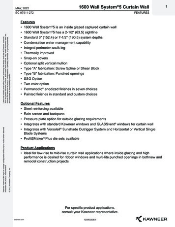
channel system, connect 5 Upper Monitors to each of the output connectors. The maximum total length of the Coax Cables connected to any one output is 400 feet. A maximum of 20 Upper Monitor sets can be connected on a single Coax line. The system is designed to work with the monitor boxes connected in a daisy-chain or serial configuration. DO NOT CREATE BRANCHES OFF A MAIN LINE! See drawing below:Click here to go back to the Index.Controls and Indicators
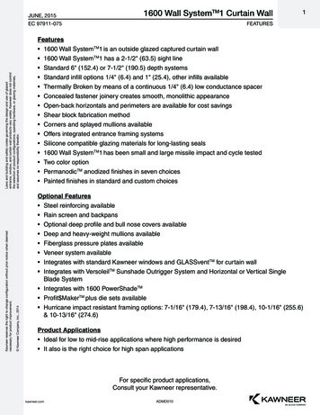
Distribution Amplifier - FrontLegend for Distribution Amplifier - Front1. Main power switchThe main power switch supplies power for the main amplifier and all monitor boxes.2. Power-on IndicatorLights when main power switch is on.3. Phone JackFor setting input volume levels.4. Channel SelectFor setting desired channel while adjusting input levels.5. Channel IndicatorIndicates current channel.6. Input Volume SelectIndicates the input volume for the currently selected channel.7. Input Volume Level
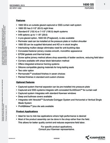
Indicates the input volume for the currently selected channel.8. Bar Graph MeterGraphic display of input volume signal.Distribution Amplifier - Back* Items found on model 1600 only.Legend for Distribution Amplifier - Back1. Power Input ConnectorThe power input connector brings 110 Vols 60 Hz AC into the system.2. Main Line FuseMain system fuse for the amplifier and all monitor boxes, 2 Amp 250 Volt Slow-Blow.3. Output #1 Circuit BreakerPower to output connectors A & B, 2 Amp.4. Output #2 Circuit BreakerPower to output connectors C & D, 2 Amp.5. P.A. (Public Address) Input
External paging system tie-in.6. Audio Inputschannel 1 - 16 audio inputs (1 - 8 on an 8 channel amplifier)7. Output ConnectorsOutput connectors to monitor boxes.8. Input Voltage SelectorSelects input voltage between 110VAC or 220VAC.Upper Monitor
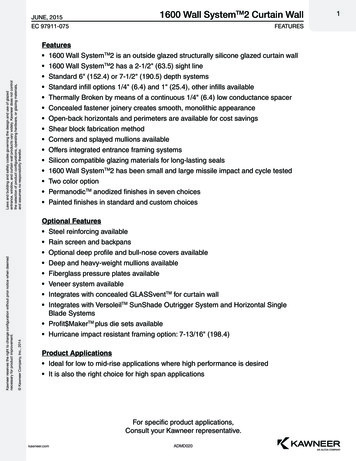
Legend for Upper Monitor1. Channel DisplayIndicates current channel selected2. Channel SelectTo select the desired listening channel3. Volume AdjustTo select the desired listening volume.4. MuteAudio mute.5. Headphone JackStandard 3.5 mm headphone jack.Floor MonitorLegend for Floor Monitor Box1. Phone JackConnector for Coiled Cable to Upper Monitor.
2. BNC ConnectorConnector for attaching Coax Cable to Floor Monitor.Click here to go back to the Index.System ConnectionsDistribution AmplifierNOTE: MAKE ALL CONNECTIONS TO MAIN AMPLIFIER, UPPERMONITORS & AUDIO DEVICES WITH POWER OFF.
Step 1 Step 2 Step 3 Step 4 Connect the audio components:to inputs 1 through 16 for a 16-channel Amplifier; orto inputs 1 through 8 for an 8-channel Amplifier.Connect the Coax Cable to outputs A,B,C, and D.A maximum of 20 Upper Monitors can be connected toa single output.For systems using multiple outputs, we recommendconnecting as follows:1 Cable to output A2 Cables to A & C3 Cables to A, B, & C4 Cables to A, B, C, & DFor a more balanced system, evenly divide the UpperMonitors among the four outputs (two outputs on an 8channel system). For example: On a system with 40Upper Monitors, install 10 on each Coax Line (20 oneach Coax Line for an 8 channel system).Connect to the optional Public Address input asfollows:Terminals #1 and #2 to the activation switch on thePA.Terminals #3 and #4 are line level from the PASystem.Use the power cord supplied to connect Main Amplifierto a 110 or 220 Volt AC outlet as applicable.CAUTION: Before connecting to 220 volt outlet besure voltage selector on back of amplifier is set to220. (See "Distribution Amplifier - Back")Upper Monitors andFloor Monitors
Step 1From the Main Amplifier, connect the Coax Cable to as manyas 20 Floor Monitors using the Coax Cable and "T"Connectors supplied, as shown above.Step 2Connect the "T" Connectors at each location to the FloorMonitor.Step 3Use the Coiled Cables to connect each Floor Monitor to anUpper Monitor.Note: The plug for the Coiled Cable is on the back of theUpper Monitor.Step 4On the last "T" Connector of each run of Coax Cable, aTerminator (supplied with this system) must be installed forproper operation.
Click here to go back to the Index.Attaching Upper MonitorsThe Upper Monitor can be installed on any piece of equipment.For equipment with round handles or railing,Upper Monitors are supplied with a build-inmounting block.Align the Upper Monitor on the handle or rail asdesired.Use two of the supplied Plastic Wire Ties toattach the Upper Monitor to the handle or rail.Pull wire ties firmly to secure.This method is the preferred method of attachingthe Upper Monitor to minimize interference withcontrol panels and displays.For equipment with flat control panels but nohand rails, SuperLock (a form of super strongvelcro) may be used.Determine the best mounting position.Clean the mounting surface thoroughly.Remove the protective cover from the adhesivestrip.Position the Upper Monitor and press firmly forthe adhesive to grip.CAUTION: When attaching to a control panel, careshould be taken to avoid blocking access tocontrols or illustrations.Click here to go back to the Index.
Setup and OperationInput Signal SetupThis procedure will adjust the audio level entering the Amplifier for each audiocomponent connected.Step1Wheninstallation iscomplete, turnpower on atthe MainAmplifier andall audiocomponents.The PowerLED and InputSignal BarGraph will lightfor 5 secondswhile thedisplay showsthe versionnumber.Step2Plugheadphonesinto the phonojack locatedunder the MainPower Switch.
Step3Step4Use theChannelSelect buttonsto select thedesiredchannel to beadjusted (leftside ofdisplay). If thechannelselected haslittleconversationor a softpassage in asong, wait fora normalsignal beforeproceeding.Use the InputVolume Selectbuttons toadjust theinput volumelevel (right sideof display).Whileobserving theInput SignalBar Graph,adjust theinput volumelevel as highas possiblewithoutlighting thered LEDs.Observe thesetting forapproximately30 secondswith a normalvolume signalto insure
proper setup.Step5Repeat steps 3and 4 for eachremainingchannel.Caution: turning up the volume level too high will causedistortion (poor sound quality) at the monitor boxes.These settings are automatically set in memory andretained when power is turned off.Click here to go back to the Index.Setup and Operation (Continued):Upper Monitor OperationChannelSelectPressChannelSelect buttonsfor desiredchannelselection (leftside ofdisplay).Press andhold eitherbutton toscroll throughchannelsrapidly.
VolumeAdjustPress VolumeAdjust buttonsfor desiredlisteningvolume. Pressand holdeither buttonto adjustvolumerapidly.Volumeautomaticallyresets to adefaultvolume whenheadphonesareunplugged.MutePress Mutebutton to turnaudio volumeon or off.Muteautomaticallyresets whenheadphonesareunplugged.Click here to go back to the Index.
SpecificationsMain AmplifierInput Sensitivity/ ImpedanceMaximum. 3.5Vrms / 30k ohmMinimum. 100mVrms / 30 k ohmGain Control Range. 31dbPower Consumption. 610 Watt MaxDimensionsWidth . 19.00" / 483 mmHeight . 3.87" / 98 mmDepth . 14.75" / 375 mmWeightModel 800 . 11 lb. / 5 KgModel 1600 . 17 lb. / 7.7 KgFloor MonitorDimensionsWidth . 4.52" / 114.8 mmHeight . 1.21" / 30.7 mmDepth . 4.85" / 123.2 mmWeight. 6.5 oz. / 184 gUpper MonitorOutput Level / Load Impedance. 550mV / 32 OhmDimensionsWidth . 2.55" / 64.8 mmHeight . 3.93" / 99.8 mmDepth . 0.97" / 24.6 mmWeight. 3 oz. / 83 gCabling
Coaxial CableSize . RG58Connectors . BNC MaleCoiled CableType. 6 Conductor, Coiled PhoneConnectors. RJ11, 6 Position 6 Fill, Pinned 1 to 1Click here to go back to the Index.Note: Cardio Theater Inc. follows a policy of continuous advancements in development. For this reasonspecifications may change without notice. For questions regarding any specifications, please call theService Center at (800) 776-6695.
Cardio Theater Inc. Service Department Telephone: 1-800-776-6695 E-mail: service@cardiotheater.com Table of Contents (Click to jump to the page you want to see.) . Headphone Jack Standard 3.5 mm headphone jack. Floor Monitor Legend for Floor Monitor Box 1. Phone Jack Connector for Coiled Cable to Upper Monitor. 2. BNC Connector