Transcription
GT-600/GT-800Portable Appliance TesterUsers ManualGB
GT-600/GT-800 Instruction Manual2
GT-600/GT-800 Instruction ManualA MPROBEGT-600/GT-800Instruction Manualc 2012 BEHA-AMPROBE3R
GT-600/GT-800 Instruction ManualTable of Contents:Safety information, Warning. 6Introduction . 7Product description . 7Scope of Supply . 8Available Accessories . 8Transport and Storage . 8Safety Measures . 9Appropriate Usage . 10Operation Elements and Connectors . 11Front panel of the GT-600 Tester . 11Front panel of the GT-800 Tester . 12Cover of the GT-600 Tester . 13Cover of the GT-800 Tester . 14Preparation of the GT-600/GT-800 Tester . 15Turning on the GT-600/GT-800 Tester . 15Test lead compensation . 15Limit value setting . 16Start of the measurement . 16External Voltage Display . 16Testing Appliances . 16Visual Inspection . 17Protective Bonding Test 5 A / 0.2 A (RPE) . 18Insulation Resistance Test 250 V / 500 V (RISO) . 21Substitute Leakage Current Test (ISUB) . 24Protective Conductor Current Test (IPE( )) . 26Touch Current Test (IT) . 28Power, Load Current Test (P/IL) . 31Clamp Current Test () (GT-800 only) . 33IEC CORD Test (CORD/PRCD) . 35PRCD Test (CORD/PRCD) (GT-800 only). 37Protective Extra Low Voltage Test (PELV) . 40Safety Extra Low Voltage Test (SELV) . 41AUTO Test (GT-800 only). 42Menu Functions . 46General operation instructions . 46MEMORY Menu . 47OPERATOR Menu . 47AUTO-TEST Menu . 48SETUP Menu . 49LANGUAGE Menu . 50CONTRAST Menu . 50TESTER INFO Menu . 50Memory Features . 51Memory Structure . 51General Memory Operations . 53Memorizing Example . 54Recall Data . 56Entry of Memory Address Using External Keyboard . 57Entry of Memory Address Using Barcode Reader . 594
GT-600/GT-800 Instruction ManualMaintenance . 60Cleaning . 60Calibration Interval . 60Fuse Replacement . 61List of Possible Displayed Errors . 62Reset of the GT-600/GT-800 Tester . 63Pre-Tests and Protection . 64Technical Specifications . 67Limited Warranty and Limitation of Liability . 74Service . 745
GT-600/GT-800 Instruction ManualSafety information, WarningMeasurements of the electrical safety on appliances should only be carried outby properly trained and competent persons!Carefully read the safety information before using the appliance testerGT-600/GT-800.References marked on the instrument or in this instruction manual:Warning of a potential danger, comply with instruction manual. Reference, please pay utmost attention.Caution, dangerous voltage. Danger of electrical shock.Symbol for marking of electrical and electronic equipment(WEEE Directive).Conformity symbol, the instrument complies with the validdirectives. It complies with the EMC Directive and the LowVoltage Directive.WARNING The instruction manual contains information and references, necessary forsafe operation and maintenance of the instrument. Prior to using theinstrument, the user is kindly requested to thoroughly read theinstruction manual and comply with it in all sections. Failure to read the instruction manual or to comply with the warningsand references contained herein can result in serious bodily injury orinstrument damage.6
GT-600/GT-800 Instruction ManualIntroductionYou have acquired a high-quality measurement instrument manufactured byBEHA-AMPROBE, which will enable you to perform repeatable measurementsfor a very long period of time.The portable appliance tester GT-600/GT-800 is a measurement instrument usedfor safety inspection on electrical appliances complying with VDE 0701-0702 anddocumentation of test results.Product description: Protective bonding resistance measurement (RPE), test current 0.2 A AC and 5A AC. The test is carried out on plugged and also on permanently connectedappliances.Insulation resistance measurement (RISO), test voltage 500 VDC (and 250 VDCGT-800 only). Appliances class I with heater, class I, class II and class III can betested.Substitute leakage current measurement (ISUB), test voltage 45 V AC.Appliances class I and class II can be tested.Protective conductor current measurement (IPE( )), differential method.Touch current measurement (IT) direct method.Apparent power, active power, mains voltage, load current and power factorPF measurement (P/IL).Protective conductor current IPE and load current IL measurement (),clamp method (GT-800 only).IEC CORD test (PE continuity, insulation resistance, L continuity, N continuity,L/N shorted).Test of portable RCD (PRCD), PE continuity, TEST button, output insulationresistance, PE current, functional test at L disconnection, functional test at Ndisconnection, trip out time at I N/2, trip out time at I N, trip out time at 5I N, tripping current (GT-800 only).Protective extra low voltage (PELV) measurement.Safety extra low voltage (SELV) measurement.AUTO Test (13 factory-programmed AUTO-Tests, 17 customer-created AUTOTests) (GT-800 only).Extremely easy operation using the rotary switch and the START/STOPbutton.Automatic start and save function for protective bonding resistancemeasurement allows both-hands measurements on measured objects thatare difficult to access.Compensation of test lead resistance for protective bonding resistancemeasurement.Calculation of limits for protective bonding resistance.Automatic mains voltage polarity exchange at protective conductor currentand touch current measurements (GT-800 only).Data memory for over 1000 measurement results.Integrated interface (USB 2.0) for transfer of measurement results to PC.Separate interface (USB 2.0) for connection of optional USB barcode reader,USB keyboard, USB memory stick or USB printer.7
GT-600/GT-800 Instruction Manual Graphic LC-Display for measurement values, limit values and test parameters.Compact plastic housing with accessory bag.Connection diagrams and limit values in instrument’s cover.Limit values adjustable through measurement range in all functions (exceptP/IL and CLAMP).Visual and acoustic warnings in case of exceeded limit value.Limits predefined for German and English region.Real time clock for documentation of test results.Single or continuous measurements.Adjustable measurement times in single measurement mode.Three selectable languages (English, German and French)Scope of Supply1 pc1 pc1 pc1 pc1 pc1 pc1 pc1 pcPortable Appliance Tester GT-600/GT-800 with permanently connectedmains cable (Schuko)Accessory bag (fixed to housing)Test lead, 1.5 m, 600 V CAT III, blackAlligator Clip 10 A, 600 V, CAT II, blackTest tip 4 mm, 600 V CAT II, blackUSB interface cableCD with USB drivers and instruction manualsInstruction manual in English/German/FrenchAvailable AccessoriesPC Software for creation of test reports “es control prof“ (No. 2390081)USB Barcode reader (BC-MT204S, No. 3504407)USB Keyboard English version (KBUK-MT204S, No. 3504395)USB Keyboard German version (KBGE-MT204S, No. 3504388)Current clamp adapter CHB-1 (No. 2390055) measuring range 0.001 A . 60 A(for leakage/load current measurements)Clamp Adapter ACF-6A (No. 2743889)PE Socket adapter Adapter-PE (No. 4151659)Brush test probe PAT-BRUSH (No. 4151667)Transport and StoragePlease keep the original packaging for potential later transport, e.g. forcalibration. Any transport damage due to faulty packaging will be excludedfrom warranty claims.Instruments must be stored in dry and closed areas. In case of an instrumentbeing transported in extreme temperatures, a recovery time of minimum 2 hoursis required prior to instrument operation.8
GT-600/GT-800 Instruction ManualSafety MeasuresThe GT-600/GT-800 appliance tester has been built and tested in compliance withthe valid safety regulations and left the factory in safe and perfect condition. Inorder to maintain this condition and to ensure safe instrument operation, theuser must pay attention to the references and warnings contained within thisinstruction manual.WARNING, DANGER OF ELECTRICAL SHOCK In order to avoid electrical shock, the valid safety and national regulationsregarding excessive contact voltages must receive utmost attention whenworking with voltages exceeding 120V DC or 50V RMS AC.The respective accident prevention regulations established by the nationalhealth & safety board for electrical systems and equipment must be strictlymet at all times.Prior to any operation, ensure that the instrument, test leads, mains cableand accessories are in perfect condition.The instrument may only be connected to mains voltage as indicated in thetechnical specification section.The instrument may only be used within the operating ranges as specified inthe technical specification section.Only touch test leads and test probes at handle area provided. Never directlytouch test probes. Direct contact to measurement connectors or test probesmust be avoided at any time.The instrument may only be used in dry and clean environments. Dirt andhumidity reduce insulation resistance and may lead to electrical shocks, inparticular for high voltages.Never use the instrument in precipitation such as dew or rain. In case ofcondensation due to temperature jumps, the instrument may not be used.A perfect display of measurement values may only be ensured within thetemperature range of 0 C to 40 C.Prior to opening the instrument ensure that it is switched off anddisconnected from all current circuits.To ensure a safe measurement only use original test leads and accessories.If the operator’s safety is no longer guaranteed, the instrument is to be putout of service and protected against use. The safety can no longer beguaranteed if the instrument (or test leads):– shows obvious damage– does not carry out the desired measurements– has been stored for too long under unfavourable conditions– has been subjected to mechanical stress during transport.Dangerous voltages may be present on appliances or device under test (DUT)caused by insulation test. Do not touch the appliances under test, danger ofelectrical shock!Start any test series by protective bonding resistance measurement.At protective bonding resistance test, insulation test and substitute leakagetest, unit under test must be voltage-free. If necessary check the unit isvoltage-free i.e. by using a voltage tester.Accidental measurement of a defective unit may trip an RCD (residualcurrent device).9
GT-600/GT-800 Instruction ManualAppropriate UsageWARNING The instrument may only be used under those conditions and for thosepurposes for which it was conceived. For this reason, in particular the safetyreferences, the technical data including environmental conditions and theusage in dry environments must be followed.When modifying the instrument, the operational safety is no longer ensured.The instrument may only be opened by an authorised service technician.Before opening, the instrument must be switched off and disconnected fromany electrical circuit.10
GT-600/GT-800 Instruction ManualOperation Elements and ConnectorsFront panel of the GT-600 TesterFigure 1: Operational elements and connectors on GT-600 Tester11
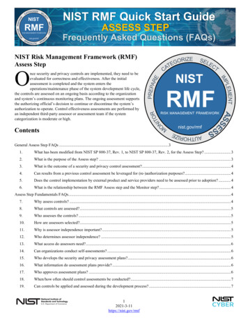
GT-600/GT-800 Instruction ManualFront panel of the GT-800 TesterFigure 2: Operational elements and connectors on GT-800 Tester1 .2 .3 .4 .5 .6 .7 .8 .9 .10 .11 .12 .13 .14 .15 .16 .17 .Mains input fuse F1 T16 A (H) / 250 V, 5 20 mmMains input fuse F2 T16 A (H) / 250 V, 5 20 mmSoft menu keys F1 . F4ON/OFF mains switch with red pilot lampFunctional menu keys F4 . F8, SAVE (to save test result), RCL (to recallsaved test result), MENU (to use menu functions) and EXIT (to exit currentmenu level)Measurement function selector switchSTART/STOP button (to start or stop selected measurement function)ON red pilot lamp, measurement activeTest/mains socketFuse for RPE function F3 FF6.3 A (H) / 250 V, 5 20 mmCLAMP input connector (GT-800 only)Green test socket (PROBE 1)Red test socket (PROBE 2)IEC test socket (for CORD test and PRCD test)USB2 interface for USB barcode reader, keyboard or memory stickUSB1 interface for PCGraphic LC-Display for measurement values, limit values and parameters.12
GT-600/GT-800 Instruction ManualCover of the GT-600 Tester, connection diagrams and limit valuesFigure 3: Brief instructions with limit values (GT-600)13
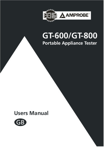
GT-600/GT-800 Instruction ManualCover of the GT-800 Tester, connection diagrams and limit valuesFigure 4: Brief instructions with limit values (GT-800)Measurement accessories are stored in the accessory bag on the top of thetester.14
GT-600/GT-800 Instruction ManualPreparation of the GT-600/GT-800 TesterTurning on the GT-600/GT-800 Tester1) Connect the GT-600/GT-800 to a correctly installed Schuko mains socket.2) Use the mains switch “ON/OFF“ (4) to turn on the GT-600/GT-800.3) After turning on the GT-600/GT-800, pilot lamp of the power switch (4)will switch on and the display (17) will show idle readout of selectedfunction. The GT-600/GT-800 is now ready for use.Test lead compensationThe GT-600/GT-800 appliance tester leaves the factory with uncompensated testlead. We recommend to compensate test lead before starting the RPE tests,otherwise result may not be correct and warning note “TEST LEAD NOTCOMPENSATED” will be displayed for a moment after pressing the “START” key.1) Set the measurement function selector (6) to RPE position.2) Connect test lead according to the figure below.3) Press the “COMP” key (soft menu key F2) then start the measurementby pressing the “START” button (7). Pilot lamp “ON” (8) indicates theactive measurement, then the result using uncompensated test lead isdisplayed for a moment. Another regular measurement is doneautomatically using compensated test lead, now the result should benearly zero. In the upper display line the character “C“ (Compensated)appears as the information that test lead is compensated.Figure 5: Connection for test lead compensation The compensation is used in all further RPE measurements. It will beactive even after switching off the GT-600/GT-800 appliance tester. The compensation is always carried out using test current of 5 A.Cancel actual test lead compensation:Open test loop (disconnect test lead from terminal PROBE 1 or PROBE 2) andcarry out the compensation as described above. The result 11.00 will bedisplayed and “C” mark will disappear from the top display line.15
GT-600/GT-800 Instruction ManualLimit value settingLimit value is offered in all functions except in P/IL and CLAMP. For limit valuesetting press the “LIM” key (soft menu key F4) then use the soft menu keys “ ”,“–“, “STD” (Standard) or “CALC” (Calculation). The soft menu key F8 “EXIT” canbe used to exit limit value setting display. In case that test result comply with set limit value, the mark “ ” isdisplayed and two short sound signals are present after finishing themeasurement. In case of non-compliance, the mark “X” is displayed andone longer sound signal is present after finishing the measurement. Thelimit value is saved as a parameter of the measurement result and istransferred to PC in case of data transfer.Start of the measurement For single measurement press the START key and release it. In this casemeasurement time is defined in MENU/SETUP/MEASUREMENT TIMES menu,see the chapter “SETUP menu” on page 49. Watch elapsed time on displayedbar graph during the measurement. For continuous measurements press and keep pressing the START key for atleast 2 seconds until “CONT” (continuous) information is displayed.Measurement time is limited to 5 minutes in this case. Continuousmeasurement is available in all functions except in CORD, PRCD and AUTOtest.External Voltage Display If there is a dangerous external voltage present on test terminals prior to atest or during it, the warning message “EXTERNAL VOLTAGE!“ will appear onthe display and the start of the measurement is blocked. Remove the externalvoltage! If an external voltage is applied to test terminals during the test in RISOfunction, wrong measurement values may be displayed.Please remove external voltage from any test terminalimmediately if “ EXTERNAL VOLTAGE!” warning is displayed.Testing AppliancesWARNINGS Before commencing any testing you are strongly advised to make reference tothe local regulations and standards for safety at works regulations and anyrelevant publications from the Health and Safety Executive. The appliance must be switched on for all tests. When conducting tests do not touch the appliance as some tests involve highvoltages and high currents.16
GT-600/GT-800 Instruction Manual The tests should only be performed by competent persons who are familiarwith the requirements of the type of tests suitable for portable appliances. It is potentially hazardous for both user and appliance should the wrong typeof tests be undertaken or if testing is carried out in an incorrect sequence. It is important that you fully understand the various tests required and howthey should be performed. The appliance must have passed the visual inspection, the protective bondingresistance test (class I), and the insulation test (in this sequence) prior to anyother test. If any of these fail further testing must be stopped and any faultsmust be rectified. During the protective conductor current test, the touch current test and theload test, the appliance will be energized at mains voltage. For this purpose,switch on the appliance. Appliances driven by motors or equipped withheating units may present a danger for the person testing (comply with theappliance instruction manual!). Please ensure that the appliance is in a safecondition to run and secure prior to testing.Visual InspectionVisually inspect the appliance before starting electrical tests.Check the appliance for the following: Condition of the appliance cables, i.e. no cuts, cracks or any physical damageto the outer insulation layer.Condition of the plug, cable securely attached, no signs of overheating andthat fitted fuses are correctly rated.Any signs of damage, and that any mains or control switches will physicallyswitch on and off.Any sockets for sign of overheating or physical damage.17
GT-600/GT-800 Instruction ManualProtective Bonding Test 5 A / 0.2 A (RPE)The protective bonding test measures the resistance between PE terminal of testsocket and PROBE 1 terminal. This test applies to class I appliances only.Remarks: To obtain correct protective bonding test results you must havecompensated (zeroed) the test lead, see the section “Test leadcompensation” on page 15. Connect the appliance and the earth bond test lead according to the figure 6or 7. You should use the lower test current 0.2 A for certain appliances. Pleaserefer to local appliance test standards and guidance material. During the measurement flex the flexible cord along its length to help findany broken conductors or poor quality joints.Figure 6: Protective bonding test connections at appliance with mains plugFigure 7: Protective bonding test connections at permanently connectedappliance18
GT-600/GT-800 Instruction ManualDisplay explanation:Figure 8: Display in protective bonding test RPE1 . “F: AUT” / “F: MAN” soft menu key, for selection of automatic /manual start and store function.2 . “COMP” soft menu key, for test lead compensation.3 . “Im” soft menu key, for test current selection (0.2 A or 5 A).4 . “LIM” soft menu key, for pass/fail limit value setting.5 . Test result status ( . result OK, X . result not OK).6 . Selected test current (0.2 A or 5 A).7 . Pre-set pass/fail limit value.8 . Test lead compensation mark (C . compensated, blank . notcompensated).9 . Selected mode of start and save function (MAN, AUT).MAN (Manual) . Use START key to start the measurement.AUT (Automatic) . The test is started automatically after connectingPROBE 1 to conductive part of tested appliance. Result isautomatically stored to last selected storage address. START key is notactive in this mode.10 . Function selected by the rotary switch (6).11 . Test result and unit.Note:In case that protective bonding test fails, the pass/fail limit value can berecalculated by using the “LIM” and “CALC” keys and entering the lengthand cross section of the mains lead. The last measurement value will bedeleted, and a new test has to be performed.19
GT-600/GT-800 Instruction ManualPass/fail limit value calculation:Cross section A 1.5 mm22.5 . 50 mm2Cable length L 5m 5 . 12.5 m 12.5 . 20 m 20 . 27.5 m 27.5 . 35 m 35 . 42.5 m 42.5 . 50 m 50 m1 . 50 m (res. 0.5 m)Limit value0.3 0.4 0.5 0.6 0.7 0.8 0.9 1.0 RLIM .L/AWhere: . 0.01786 mm2/m (specific resistance of Cu)L . cable length in mA . cross section in mm2Specific information that can be shown on the display:Information displayedTEST LEADNOT COMPENSATED 5 , NOT COMPENSATEDCOMP?EXTERNAL VOLTAGEUSE PROBE 1 11.00 X DescriptionTest lead is not compensated (no “C” mark onthe display)! It is recommended tocompensate the test lead.Compensation was not successfully done dueto too high compensation value ( 5.00 )!Test lead is wrong compensated (negative RPEresult 0.05 ). Compensate the test leadagain.External voltage is applied to one or moretest terminals, see the explanation in section“Pre-Tests and Protection, Functions andMessages”.Test lead is connected to PROBE 2. Reconnectit to PROBE 1.RPE value higher than 11.00 (over-range),possibly because of open test lead.In order to save displayed measurement result, press the “SAVE” functionkey (F5) twice, for further instructions see the “Memorizing example”section.20
GT-600/GT-800 Instruction ManualInsulation Resistance Test 250 V / 500 V (RISO)The insulation resistance test measures the resistance of the insulation between: L/N terminals of test socket and PE terminal of test socket in parallel withPROBE 2 (at class I and class II). L/N terminals are shorted by the tester for thistest. Test probe PROBE 1 and test probe PROBE 2 (at class III).Warnings The test voltage is either 500 V (or 250 Vd.c. at GT-800 only). Do nottouch the appliance during the insulation test! If the test fails, any metalpart of the appliance could become live!Always make sure that the test has completed before disconnecting theappliance leads to ensure that all capacitances have discharged!Cautions Do not perform the Insulation test on appliances that failed theprotective bonding test or the visual inspection test.The insulation test may not be suitable for some types of appliances. Forthese appliances an alternative test may be conducted such as touchcurrent, protective conductor current or substitute leakage current test.It is essential to refer to the local appliance test standards and/orreference material for the safe applicability of these alternative tests.Test voltage of 500 V may not be suitable for some appliances thatcontain overvoltage protection devices (e.g. varistors) in its installation.For these appliances test voltage of 250 V shall be used, refer to thelocal appliance test standards and/or follow the manufacturerrecommendations.Remarks: Connect the appliance and the test lead according to the figure 9, 10 or 11. For class I appliances no probe is required except if there are some metalparts on the appliance which are not connected to PE terminal. For class II appliances apply the test probe to any exposed metalwork on theappliance. Do the test for all exposed metal parts on the appliance, partialresults must pass pre-set limit value.Figure 9: Insulation resistance test connections at appliance class I21
GT-600/GT-800 Instruction ManualFigure 10: Insulation resistance test connections at appliance class IIFigure 11: Insulation resistance test connections at appliance class IIIDisplay explanation:Figure 12: Display in insulation resistance test RISO1 . “PC” soft menu key, for selection of protection class (PC I-HEATER,PC I, PC II or PC III).2 . “UISO” soft menu key, for selection of test voltage (250 V or 500 V).3 . “LIM” soft menu key, for pass/fail limit value setting.4 . Test result status ( . result OK, X . result not OK).5 . Selected protection class (PC I-HEATER, PC I, PC II or PC III).6 . Selected test voltage 500 V (or 250 V at GT-800 only).7 . Pre-set pass/fail limit value.8 . Function selected by the rotary switch (6).9 . Test result and unit.22
GT-600/GT-800 Instruction ManualSpecific information that can be shown on the displayInformation displayedEXTERNAL VOLTAGEUSE PROBE 2 100M 20.0M DescriptionExternal voltage is applied to one or moretest terminals, see the explanation in section“Pre-Tests and Protection, Functions andMessages”.Test lead is connected to PROBE 1. Reconnectit to PROBE 2.RISO value higher than 100 M (over-range).Measurement range in class I / II is 100 M .RISO value higher than 20.0 M (over-range).Measurement range in clas
Users Manual GB. GT-600/GT-800 Instruction Manual 2 . GT-600/GT-800 Instruction Manual 3 AMPROBE R GT-600/GT-800 Instruction Manual c2012 BEHA-AMPROBE. GT-600/GT-800 Instruction Manual 4 Table of Contents: