Transcription
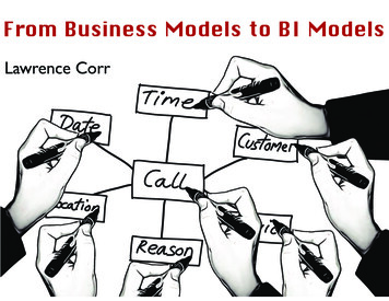
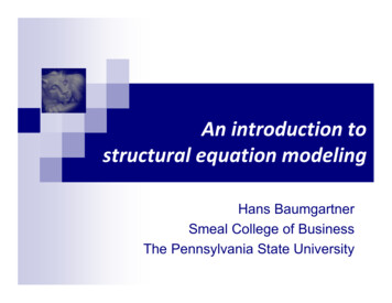
1Introduction to Systems Modeling Concepts(Chapter 1 from Zeigler, B. P., H. Praehofer and T. G. Kim (2000). Theory of Modeling and Simulation:Integrating Discrete Event and Continuous Complex Dynamic Systems, (2nd Ed.) Academic Press, NY.)This chapter introduces some key concepts that underlie the framework and methodology for modeling andsimulation (M&S) originally presented in “Theory of Modeling and Simulation” published in 1976 referred tohereafter as TMS76 to distinguish it from the current revised edition TMS98. Perhaps the most basic concept isthat of mathematical systems theory. First developed in the nineteen sixties, this theory provides a fundamental,rigorous mathematical formalism for representing dynamical systems. There are two main, and orthogonal,aspects to the theory: levels of system specification – these are the levels at which we can describe how systems behave and themechanisms that make them work the way they do. systems specification formalisms – these are the types of modeling styles, such continuous or discrete, thatmodelers can use to build system models.Although the theory is quite intuitive, it does present an abstract way of thinking about the world that you willprobably find unfamiliar. So we introduce the concepts in a spiral development consisting of easy-to-grasp stages with each spiral revolution returning to a more faithful version of the full story.In this chapter we first introduce some basic systems concepts, then motivate the systems specificationformalisms by describing their evolution over time. This also provides a way to point out the differences betweenTMS98 and its predecessor. Finally, we discuss the levels of system specification, illustrating them with familiarexamples. In this ground stage of our spiral development, the presentation is informal and prepares the way forthe framework for M&S that comes in the next chapter. Later, in the second part of the book, we return to a morerigorous development of the concepts to lay a sound basis for the developments to come in the third part.1.1Systems Specification FormalismsSystem theory distinguishes between system structure (the inner constitution of a system) and behavior (itsouter manifestation). Viewed as a black box (Figure 1) the external behavior of a system is the relationship itimposes between its input time histories and output time histories. The system’s input/output behavior consists ofthe pairs of data records (input time segments paired with output time segments) gathered from a real system ormodel. The internal structure of a system includes its state and state transition mechanism (dictating how inputstransform current states into successor states) as well as the state-to-output mapping. Knowing the systemstructure allows us to deduce (analyze, simulate) its behavior. Usually, the other direction (inferring structurefrom behavior) is not univalent – indeed, discovering a valid representation of an observed behavior is one of thekey concerns of the M&S enterprise.1
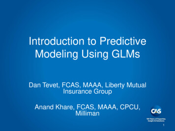
1965SYSTEMoutputinputstateFigure 1Basic System ConceptsAn important structure concept is that of decomposition namely, how a system may be broken down intocomponent systems (Figure 2). A second concept is that of composition, i.e., how component systems may becoupled together to form a larger system. Systems theory is closed under composition in that the structure andbehavior of a composition of systems can be expressed in the original system theory terms. The ability tocontinue to compose larger and larger systems from previously constructed components leads to hierarchicalconstruction. Closure under composition guarantees that such a composition results in a system, called itsresultant, with well defined structure and behavior. Modular systems have recognized input and output portsthrough which all interaction with the environment occurs. They can be coupled together by coupling outputports to input ports and can have hierarchical structure in which component systems are coupled together to formlarger ones.The difference between a decomposed systems, as in Figure 2, and undecomposed systems, as in Figure 1,provides our first introduction to levels of systems specification. We’ll say later that the former are at a higherlevel of specification than the latter since they provide more information about the structure of the system.1.1.1Relation To Object OrientationModels developed in a system theory paradigm bear a resemblance to concepts of object-oriented programming.Both objects and system models share a concept of internal state. However, mathematical systems are formalstructures that operate on a time base while programming objects typically do not have an associated temporalsemantics. Objects in typical object oriented paradigms are not hierarchical or modular in the sense justdescribed. The coupling concept in modular systems provides a level of delayed binding a system model canplace a value on one of its ports but the actual destination of this output is not determined until the modelbecomes a component in a larger system and a coupling scheme is specified. It can therefore: a) be developedand tested as a stand alone unit, b) be placed in a model repository and reactivated at will and c) reused in anyapplications context in which its behavior is appropriate and coupling to other components makes sense.2
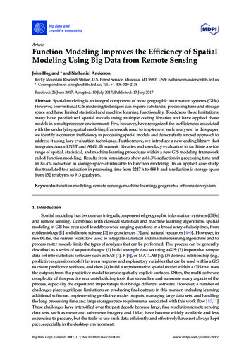
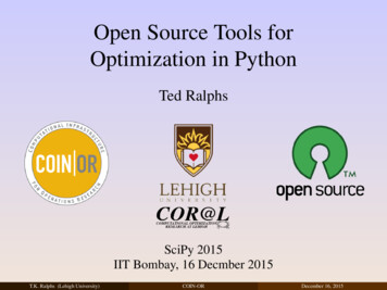
Figure 2Hierarchical System DecompositionWhile coupling establishes output-to-input pathways, the systems modeler is completely free to specify how dataflows along such channels. Information flow is one of many interactions that may be represented. Otherinteractions include physical forces and fields, material flows, monetary flows, and social transactions. Thesystems concept is broad enough to include the representation of any of these and supports the development ofM&S environments that can make including many within the same large-scale model.Although systems models have formal temporal and coupling features not shared by conventional objects, objectorientation does provide a supporting computational mechanism for system modeling. Indeed, there have beenmany object-oriented implementations of hierarchical, modular modeling systems. These demonstrate that objectoriented paradigms, particularly for distributed computing, can serve as a strong foundation to implement themodular systems paradigm.1.1.2Evolution Of Systems FormalismsAs in many situations, portraying the evolution of an idea may help in the understanding of the complexities asthey develop. 0 depicts the basic systems modeling formalisms as they were presented in the frist edition,TMS76. This edition was the first book to formulate approaches to modeling as system specification formalisms– shorthand means of delineating a particular system within a subclass of all systems. The traditional differentialequation systems, having continuous states and continuous time, were formulated as the class of DESS(Differential Equation System Specifications). Also, systems that operated on a discrete time base such asautomata were formulated as the class of DTSS (Discrete Time System Specifications). In each of these cases,mathematical representation had proceeded their computerized incarnations (it has been three hundred years sinceNewton-Leibnitz!).3
System Specification Formalism:Simulator:NumericalIntegratorSystemDESS: differential equationDTSS: difference equationDESS model:dq/dt a*q bxDEVS: discrete gorithmSystemSystemDEVS modelDTSS model:time to next event,q(t 1) a*q(t) b*x(t)state at next event .Figure 3Basic Systems Specification FormalismsHowever, the reverse was true for the third class, the Discrete Event System Specifications (DEVS). Discreteevent models were largely prisoners of their simulation language implementations or algorithmic codeexpressions. Indeed, there was a prevalent belief that discrete event “world views” constituted new mutant formsof simulation, unrelated to the traditional mainstream paradigms. Fortunately, that situation has begun to changeas the benefits of abstractions in control and design became clear. Witness the variety of discrete event dynamicsystem formalisms that have emerged [Ho 94]. While each one – examples are Petri Nets, Min-Max algebra, andGSMP (generalized semi-markov processes) – has its application area, none were developed deliberately assubclasses of the systems theory formalism. Thus to include such a formalism into an organized system-theorybased framework requires “embedding” it into DEVS.4
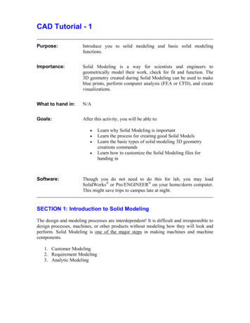
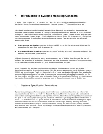
1976SYSTEMDEVSDiscrete EventSystem SpecificationDESSDifferential EquationSystem SpecificationDTSSDiscrete TimeSystem SpecificationFigure 4The Dynamics of Basic System Classes“Embedding.” What could such a concept mean? The arrows in Figure 4 indicate subclass relationships; forexample, they suggest that DTSS is a “subclass of” DEVS. However, it is not literally true that any discrete timesystem is also discrete event system (their time bases are distinct, for example). So we need a concept ofsimulation that allows us to say when one system can do the essential work of another. One formalism can beembedded in another if any system in the first can be simulated by some system in the second. Actually, morethan one such relationship, or morphism, may be useful, since, as already mentioned, there are various levels ofstructure and behavior at which equivalence of systems could be required. As a case in point, the TMS76 editionestablished that any DTSS could be simulated by a DEVS by constraining the time advance to be constant.However, this is not as useful as it could be until we can see how it applies to decomposed systems. Until that istrue, we either must reconstitute a decomposed discrete time system to its resultant before representing it as aDEVS or we can represent each DTSS component as a DEVS but we can’t network the DEVS together tosimulate the resultant. The current edition, TMS98, establishes this stronger simulation relation (Chapter 15).1990SYSTEMDEV&DESSDiscrete Event &Differential EquationSystem SpecificationDEVSDiscrete EventSystem SpecificationDESSDifferential EquationSystem SpecificationDTSSDiscrete TimeSystem SpecificationFigure 5Introducing the DEV&DESS Formalism5
1.1.3Combining Continuous And Discrete FormalismsSkipping many years of accumulating developments, the next major advance in systems formalisms was thecombination of discrete event and differential equation formalisms into one, the DEV&DESS. As shown inFigure 5, this formalism subsumes both the DESS and the DEVS (hence also the DTSS) and thus supports thedevelopment of coupled systems whose components are expressed in any of the basic formalisms. Suchmultiformalism modeling capability is important since the world does not usually lend itself to using one form ofabstraction at a time. For example, a chemical plant is usually modeled with differential equations while itscontrol logic is best designed with discrete event formalisms. In 1990, one of the authors of this book showedthat DEV&DESS was closed under coupling and in order to do so, had to deal with the pairs of input-outputinterfaces between the different types of systems. Closure under coupling also required that the DEV&DESSformalism provide a means to specify components with intermingled discrete and continuous expressions.Finally, simulator algorithms (so called abstract simulator) had to be provided to establish that the newformalism could be implemented in computational form (look ahead to Chapter 9 to see how this was actDISCRETIZEDDESSas close asDESSFigure 61.1.4desiredDESSIntroducing Quantized SystemsQuantized SystemsThe current edition, TMS98, builds on the advances since 1976 especially in the directions pointed to by theintroduction of DEV&DESS. Since parallel and distributed simulation is fast becoming the dominant form ofmodel execution, and discrete event concepts best fit with this technology, our focus is on a concept called theDEVS bus. This concept, introduced in 1996 by another of the authors and his students, concerns the use ofDEVS models, as a “wrappers” to enable a variety of models, to interoperate in a networked simulation. It isparticularly germane to the High Level Architecture (HLA) defined by the United States Department of Defense.One way of looking at this idea is that we want to embed any formalism, including for example, theDEV&DESS, into DEVS. Another way is to introduce a new class of systems, called the Quantized System, asillustrated in Figure 6. In such systems, both the input and output are quantized. As an example, an analog-todigital converter does such quantization by mapping a real number into a finite string of digits. In general,quantization forms equivalence classes of outputs that then become indistinguishable for downstream inputreceivers, requiring less data network bandwidth, but also possibly incurring error.6
Quantization provides a process for representing and simulating continuous systems that is an alternative to themore conventional discretization of the time axis. While discretization leads to discrete time systems,quantization leads to discrete event systems. The beginnings of a theory of quantized systems are presented inChapter 16 of this book. When we restrict quantization to differential equation systems, we can express theresulting class, Quantized DESS, within DEV&DESS and study its properties, especially from the point of viewof the DEVS bus. We can then study the approximation capability and simulation efficiency of DEVS indistributed simulation in comparison with classical time stepped integration and simulation approaches.Particularly with respect to reduction of message passing and network bandwidth (a major concern in distributedsimulation) promising results are being obtained.1.1.5Extensions of DEVSVarious extensions of DEVS have been developed as illustrated in Figure 7. They will be discussed in Chapter10. These developments expand the classes of system models that can be represented in DEVS, and hence,integrated within both the DEVS bus and the parent systems theory TENSIONSOF DEVSDYNAMICSTRUCTUREDEVSDEVSREAL TIMEDEVSFUZZYDEVSFigure 7Extensions of the DEVS FormalismThese developments lend credence to the claim that DEVS is a promising computational basis for analysis anddesign of systems, particularly when simulation is the ultimate environment for development and testing (Figure8). The claim rests on the universality of the DEVS representation, namely the ability of DEVS bus to support thebasic system formalisms. This edition goes some distance toward substantiating the claim that DEVS is theunique form of representation that underlies any system with discrete event behavior. This uniqueness claim ofDEVS, discussed in Chapter 15, offers the promise that the profusion of discrete event formalisms underdevelopment for control and management of systems can be embedded as subformalisms of DEVS in the DEVSbus and thus made accessible in an integrated distributed simulation environment.7
1997DEVS REPRESENTABLESYSTEMSUNIVERSALITYOF DEVSRepresentationQUANTIZEDSYSTEMSUNIQUENESSOF DEVS as DEDSrepresentationDEVSFigure 81.2Computationalbasis forSimulation,Design, ControlDEVS as a Computational Basis for Simulation, Design and ControlLevels of System KnowledgeAs already mentioned, the systems specification hierarchy is the basis for a framework for M&S which sets forththe fundamental entities and relationships in the M&S enterprise. The hierarchy is first presented in an informalmanner and later in Chapter 5 in its full mathematical rigor. Our presentation starts with a review of GeorgeKlir’s [Klir 1985] systems framework.LevelNameWhat we know at this level0Sourcewhat variables to measure and how to observe them1Datadata collected from a source system2Generativemeans to generate data in a data system3Structurecomponents (at lower levels) coupled together to form a generative systemTable 1Levels of System Knowledge.Table 1 identifies four basic levels of knowledge about a system recognized by Klir. At each level we know someimportant things about a system that we didn’t know at lower levels. At the lowest level, the source levelidentifies a portion of the real world that we wish to model and the means by which we are going to observe it.As the next level, the data level is a data base of measurements and observations made for the source system.When we get to Level 2, we have the ability to recreate this data using a more compact representation, such as aformula. Since typically, there are many formulas or other means to generate the same data, the generative level,or particular means or formula we have settled on, constitutes knowledge we didn’t have at the data system level.When people talk about models in the context of simulation studies they are usually referring to the conceptsidentified at this level. That is, to them a model means a program to generate data. At the last level, the structurelevel, we have a very specific kind of generative system. In other words, we know how to generate the dataobserved at Level 1 in a more specific manner in terms of component systems that are interconnected together8
and whose interaction accounts for the observations made. When people talk about systems, they are oftenreferring to this level of knowledge. They think of reality as being made up of interacting parts so that thewhole is the sum (or a sometimes claimed, more, or less, than the sum) of its parts. Although some people usethe term ‘subsystems’ for these parts, we call them component systems (and reserve the term subsystem foranother meaning).As we have suggested, Klir’s terms are by no means universally known, understood, or accepted in the M&Scommunity. However, his framework is a useful starting point since it provides a unified perspective on what areusually considered to be distinct concepts. From this perspective, there are only three basic kinds of problemsdealing with systems and they involve moving between the levels of system knowledge (Table 2). In systemsanalysis, we are trying to understand the behavior of an existing or hypothetical system based on its knownstructure. Systems inference is done when we don’t know what this structure is – so we try to guess this structurefrom observations that we can make. Finally, in systems design, we are investigating the alternative structures fora completely new system or the redesign of an existing one.Systems ProblemDoes source of the data exist?What are we trying to learn aboutit?Which level transition isinvolved?systems analysisThe system being analyzed mayexist or may be planned. In eithercase we are trying to understand itsbehavioral characteristics.moving from higher to lowerlevels, e.g., using generativeinformation to generate the data in adata systemsystems inferenceThe system exists. We are trying toinfer how it works fromobservations of its behavior.moving from lower to higher levels,e.g., having data, finding a means togenerate itsystems designThe system being designed does notyet exist in the form that is beingcontemplated. We are trying tocome up with a good design for it.moving from lower to higher levels,e.g. having a means to generateobserved data, synthesizing it withcomponents taken off the shelf.Table 2Fundamental Systems Problems.The central idea is that when we move to a lower level, we don’t generate any really new knowledge we areonly making explicit what is implicit in the description we already have. One could argue that making somethingexplicit can lead to insight, or understanding, which is a form of new knowledge, but Klir is not considering thiskind of subjective (or modeler dependent) knowledge. In the M&S context, one major form of systems analysisis computer simulation which generates data under the instructions provided by a model. While no newknowledge (in Klir’s sense) is generated, interesting properties may come to light of which we were not awarebefore the analysis. On the other hand, systems inference and systems design are problems that involve climbingup the levels. In both cases we have a low level system description and wish to come up with an equivalenthigher level one. For systems inference, the lower level system is typically at the data system level, being datathat we have observed from some existing source system. We are trying to find a generative system, or even astructure system, that can recreate the observed data. In the M&S context, this is usually called modelconstruction. In the case of systems design, the source system typically does not yet exist and our objective is tobuild one that has a desired functionality. By functionality we mean what we want the system to do; typically, wewant to come up with a structure system, whose components are technological, i.e., can be obtained off-the-shelf,9
or built from scratch from existing technologies. When these components are interconnected, as specified by astructure system’s coupling relation, the result should be a real system that behaves as desired.It is interesting to note that the process called reverse engineering has elements of both inference and design. Toreverse engineer an existing system, such as was done in the case of the cloning of IBM compatible PCs, anextensive set of observations is first made. From these observations, the behavior of the system is inferred and analternative structure to realize this behavior is designed thus bypassing patent rights to the original systemdesign!1.3Introduction to the Hierarchy of Systems SpecificationsAt about the same time (in the early 1970’s) that Klir introduced his epistemological (knowledge) levels, TMS76formulated a similar hierarchy that is more oriented toward the M&S context. This framework employs a generalconcept of dynamical system and identifies useful ways in which such a system can be specified. These ways ofdescribing a system can be ordered in levels as in Table 3. Just as in Klir’s framework, at each level moreinformation is provided in the specification that cannot be derived from lower levels. As can be seen in Table 3,these levels roughly correspond to those of Klir’s framework.LevelSpecification NameCorresponds to Klir’sWhat we know at this level0Observation FrameSource Systemhow to stimulate the system with inputs; whatvariables to measure and how to observe themover a time base;1I/O BehaviorData Systemtime-indexed data collected from a sourcesystem; consists of input/output pairs2I/O Function3State TransitionGenerative Systemhow states are affected by inputs; given a stateand an input what is the state after the inputstimulus is over; what output event is generatedby a state.4Coupled ComponentStructure Systemcomponents and how they are coupledtogether. The components can be specified atlower levels or can even be structure systemsthemselves – leading to hierarchical structure.Table 3knowledge of initial state; given an initial state,every input stimulus produces a unique output.Relation between System Specification Hierarchy and Klir’s levels.10
The major difference between the two frameworks is that the System Specification Hierarchy recognize thatsimulation deals with dynamics, the way in which systems behave over time. Therefore, time is the base uponwhich all events are ordered. We also view systems as having input and output interfaces through which they caninteract with other systems. As illustrated in Figure 9, systems receive stimuli ordered in time through their inputports, and respond on their output ports. The term “port” signifies a specific means of interacting with thesystem. Whether by stimulating it (input )or observing it (output). The time-indexed inputs to systems are calledinput trajectories; likewise, their time-indexed outputs are called output trajectories. Ports are the only channelsthrough which one can interact with the system. This means that system are modular. While Klir’s frameworkcan include dynamics, input/output ports and modularity, it is not dedicated to these concepts. However,understanding these concepts is critical to effectively solving the problems that arise in M&S.inputtrajectoryoutputtrajectorytime basetime baseSYSTEMINPUTPORTSFigure 9OUTPUTPORTSInput/Output System.Before discussing each level of the specification hierarchy in some detail, let’s observe that we could have thevery same real world object specified simultaneously at each of the levels. Thus there should be a way toassociate the next lower level specification with any given one. This association concept is illustrated in Figure10. For example, if we have know the detailed structure at the Coupled Component level, then we ought to beable to construct the corresponding specification at the State Transition level. The hierarchy is set up to providesuch an association mapping at each (other than the lowest) level. Indeed, this is the formal version of climbingdown the levels just discussed. Since the association mapping is not necessarily one to one, many upper levelspecifications may map to the same lower level one. This is the underlying reason why climbing up the levels ismuch harder than climbing down the levels. Indeed, when we select one of the associated upper levelspecifications for a given lower level one, we are gaining knowledge we didn’t have at the lower level.11
Level 4Level 4Level 4associationLevel 3Level 2Level 1Level 0Figure 10Association between levels of the System Specification Hierarchy1.4The Specification Levels Informally Presented1.4.1Observation FrameThe Observation Frame specifies how to stimulate the system with inputs; what variables to measure and how toobserve them over a time base.As an example, Figure 11 shows a forest subject to lightning, rain and wind, modeled as input ports and smokeproduced from fire, represented as an output port. This is a level 0 or Observation Frame specification. Note thechoice of variables we included as ports and their orientation (i.e., whether they are input or output ports). Wecould have chosen differently. For example, we could have included an output port to represent heat radiation.Moreover, rather than representing each variable by a single value, it can be distributed over space, i.e.,represented by an array of values. Such choices depend on our modeling objectives and are specified throughexperimental frames, a concept which we discuss in Chapter 2.Figure 12 shows some examples of input and output trajectories. The input trajectory on the lightning portshows a bolt occurring at some particular time t0. Only one such bolt occurs in the time period shown. The smokeoutput trajectory, at the top, depicts a gradual build up of smoke starting at t0 (so presumably, caused by a firestarted by the lightning bolt). The possible values taken on by smoke, called its range, would result from someappropriate measurement scheme, e.g., measuring density of particulate material in grams/cubic meter. The pairof input, and associated output, trajectories is called a input/output (or I/O) pair. Figure 12 also displays asecond I/O pair with the same input trajectory but different output trajectory. It represents the fact that there maybe many responses to the same stimulus. In the second case, lightning did not cause a major fire, since the onethat broke out quickly died. Such multiple output trajectories (for the same input trajectory) are characteristic ofknowledge at Level 1. Knowing how to disambiguate these output trajectories is knowledge we will gain at thenext level.12
Figure 11Figure 121.4.2A forest specified as a system in the Observation Frame (Level 0).Some Input-Output Pairs for the Forest System Frame of Figure 11.I/O Behavior and I/O FunctionThe collection of all I/O pairs gathered by observation is called the I/O Behavior of a system. Returning to Table3, this represents a system specification at Level 1. Now suppose that we are able to uniquely predict the responseof the smoke output to a lightning bolt. For example, suppose we know that if the vegetation is dry, then a majorfire will ignite, but if the vegetation is moist then any fire will quickly die. Having such a factor representsknowledge at Level 2, that of the I/O Function. Here, in addition to lower level information, we add initial statesto the specification when the initial state is known, there is a functional relationship between input and outputtrajectories, i.e., the initial state determines the unique response to any input (Figure 13 a).13
1.4.3State Transition System SpecificationAt the next level (3) of system specification, we can specify not only initial state information but also how thestate changes as the system responds to its input trajectory. Figure 13 b) and c) illustrate this important concept.Figure 13 b) presents the situation where the forest is in state (dry vegetation, unburned) when a lightning boltoccurs at time t0. The state that the forest is in at time t1 when a second bolt occurs is (dry vegetation, burnt)reflecting the fact that a fire has ignited. Since the forest is in a different state, the effect of this second bolt isdifferent from the first. Indeed, since there is little left to burn, there is no effect of the second bolt.In contrast, Figure 13 c) illustrates the situation where the forest is wet and unburned when the first bolt occurs. Itdoes not cause a major fire, but it does dry out the vegetation so the resulting state is (dry, unburned). Now thesecond bolt produces a major fire, just as the first bolt did in Figure 13 b) since both the state and subsequentinput trajectory are the same, the response of the system is the same.1.4.4Coupled Component System SpecificationAt the highest
Theory of Modeling and Simulation: Integrating Discrete Event and Continuous Complex Dynamic Systems, (2nd Ed.) Academic Press, NY.) This chapter introduces some key concepts that underlie the framework and methodology for modeling and simulation (M&S) originally presented in "Theory of Modeling and Simulation" published in 1976 referred to