Transcription
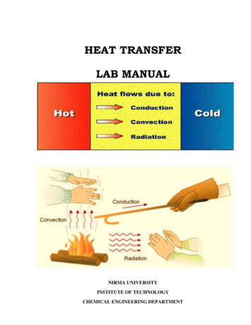
HEAT TRANSFERLAB MANUALNIRMA UNIVERSITYINSTITUTE OF TECHNOLOGYCHEMICAL ENGINEERING DEPARTMENT
Chemical Engineering DepartmentInstitute of Technology, Nirma UniversityList of Experiments:1. Thermal conductivity apparatus2. Thermal conductivity of metal rod3. Thermal conductivity of insulating powder4. Heat Transfer in natural convection5. Heat Transfer in forced convection6. Extended surface equipment7. Parallel flow heat exchanger8. Counter flow heat exchanger9. Shell and Tube heat exchanger10. Finned tube heat exchanger11.Emissivity measurement apparatus12. Drop wise and film wise condensation apparatusHeat Transfer Operation- Lab Manual
Chemical Engineering DepartmentInstitute of Technology, Nirma UniversityDate:Practical No:Roll No:THERMAL CONDUCTIVITY APPARATUSObjective: After this experiment student will able to understand how to determine the ThermalConductivity of given specimen.Apparatus: Two slab guarded hot plate thermal conductivity apparatus, Specimen, Insulation(Glass wool) Packets.Utility: Water, Electric Supply.Theory:Principle of the guarded hot plate method:A sketch of the apparatus is shown in Fig. (1). The essential parts the Hot plate, the cold plate,the heater assembly, thermocouples and the specimen, in position, are shown in the same figure.For measurement of the thermal conductivity K what is required is to have one dimensional heatflow through the flat specimen, an arrangement for maintaining its faces at the constanttemperature and metering method to measure the heat flow through a known area.To eliminate the distortion caused by the edge losses in unidirectional heat flow from the centralplate, it is surrounded by a guard ring heater separately. Temperatures are measured by calibratedthermocouples, attached to the plates or to the specimen at the hot and the cold faces. Twospecimens are used to ensure that all the heat comes out to the specimen only.Knowing the heat input to the central plate heater, the temperature difference across thespecimen, its thickness and the area, one can calculate the K by the following formula.K q*L2 A * (Th Tc )Where,KqAThTcLThermal Conductivity of the sample, W /m CHeat flow rate in the specimen, WArea of the specimen, m2Hot plate temperature, CCold plate temperature, CThickness of the specimen, mIf the specimen thickness are different and the respective hot and cold temperatures aredifferent than,q L1L2 2 A Th1 - Tc1 Th2 - Tc2 Where suffix 1 stands for upper specimen and 2 stands for lower specimen.K Heat Transfer Operation- Lab Manual
Chemical Engineering DepartmentInstitute of Technology, Nirma UniversityApparatus description:The heater plate is surrounded by a guard heater for stabilising the temperature of the primaryheater and to prevent heat loss radially around the edges. The primary and guard heaters are madeof Nichrome wire packed between upper and lower mica sheets. These heaters together withupper and lower copper plates and rings from the heater plate assembly.Two thermocouples (1 & 2) are used to measure the hot face temperature at the upper and lowercentral plate assembly copper plates. Two more thermocouples (3 & 4) are used to check balancein both the heater inputs (see figure 1).Specimens are held between the heater and cooling unit on each side of the apparatus.Thermocouples (5 & 6) measure the temperature of the upper cooling plate and lower coolingplate respectively.The cooling chamber is a composite assembly of spiral grooved Aluminium casting andaluminium cover with entry and exit adopters for water inlet and outlet.Procedure:The specimens are placed on either side of the heating plate assembly uniformly touching thecooling plates. The outer container is filled with loosely filled insulation such as glass woolsupplied in small packets. The cooling circuit is started. Then calculated heat input is given to thecentral and guard heaters through separate single phase power supply lines with dimmerstat ineach line and it is adjusted to maintain the desired temperature (For ensuring no radial heattransfer, generally outer heater input is 2.5 to 3.0 times more than the central heating input). Theguard heater input is adjusted in such a way that there is no radial heat flow, which is checkedfrom thermocouples readings are recorded accordingly. The input of the central heater (current &voltage, watts) and the thermocouple readings are recorded every 10 minutes till a reasonablysteady state condition is reached. The readings are recorded in the observation table. The finalsteady state values are taken for calculations.Precautions: Keep the dimmerstat to 0 voltage position at start. Increase the voltage gradually of the two heaters during initial set-up experimentation. Start the cooling circuit before switching on the heaters and adjust the flow rates so thatpractically there is no temperature rise in the circulation fluid. Keep the heater plate undisturbed and adjust the cooling plates after keeping the samples withthe help of nuts gently. Keep the loose filled in insulation (glass wool) packets gently and remove them slowly so thatthey do not disturb the thermocouples’ terminals and heater wires.Heat Transfer Operation- Lab Manual
Chemical Engineering DepartmentInstitute of Technology, Nirma UniversityObservation table:Sr.No.Central HeaterT1(0C)Guard HeaterT2(0C)T3(0C)T4(0C)Cooling PlateT5(0C)T6(0C)The difference between the temperatures of central heater and guard heaters should not be morethan 1 0C.V (volts)I (amp)q(watt)L (m)D (m)A (m2)K (Watt / m oC)0.0190.180.0190.18Calculation:1. Area of Heat transfer A ( / 4) * D22. Thermal Conductivity of specimenK Where,Th, av (T1 T2 ) / 2Tc, av (T5 T6 ) / 2L Thickness of slabResult:Conclusion:Heat Transfer Operation- Lab Manualq*L2 A(Th, av - Tc, av)0.0190.18
Chemical Engineering DepartmentInstitute of Technology, Nirma UniversityQuiz:1. Write the Fourier rate equation for heat transfer by conduction. Give physical significance ofeach term.2. Why there is a negative sign in the Fourier’s law of heat conduction?3. What is meant by one-dimensional steady state heat conduction?4. List some good conductors of heat; some poor conductors.5. What is the function of guard heater in Two Slab Guarded Hot Plate Method?Heat Transfer Operation- Lab Manual
Chemical Engineering DepartmentInstitute of Technology, Nirma UniversityDate:Practical No:Roll No:THERMAL CONDUCTIVITY OF METAL RODObjective: After this experiment student will able to understand how to determine the thermalconductivity of given metal rod.Apparatus: Thermal conductivity apparatus, metal rod.Utility: Water, Electric Supply.Theory:The thermal energy is conducted in solids by the following modes:(i) Lattice vibration(ii) Transport by free electronsIn good electrical conductors a large number of free electrons move about in the lattice structureof the material. They carry thermal energy from a high temperature region to a low temperatureregion. Energy may also be transmitted as vibrational energy in the lattice structure of thematerial. In general, this latter mode of transfer is not as large as the electron transport. Withincrease in the temperature, however the increased lattice vibration come in the way of thetransport by free electrons and for most of the pure metals the thermal conductivity decreaseswith increase in temperature.Apparatus Description:The experimental set up consists of metal bar, one end of which is heated by an electric heaterwhile the other end of the bar projects inside the cooling water jacket. The middle portion of thebar is surrounded by cylindrical shell filled with asbestos magnesia insulating powder. Thetemperature of the bar is measured at different sections (figure1) from 1 to 7 while the radialtemperature distribution is measured by separate thermocouples at two different sections in theinsulating shell.The heater is provided with a dimmerstat for controlling the heat input. Water under constantheat condition is circulated through the jacket and its flow rate and temperature rise is noted.Procedure:Start the electric supply. Adjust the room temperature in the temperature indicator by means ofrotating knob, for compensation of the temperature equal to the room temperature (normally thisis readjusted). Give input to the heater by slowly rotating the dimmerstat and adjust it to voltageequal to 80 to 120 volts. Start the cooling water supply through the jacket and adjust it about 350cc/ minute. Go on checking the temperatures at some specified time intervals say 5 minutes andcontinue this till a satisfactory steady state condition is reached. Note the mass flow rate of waterin kg/ min. and temperature rise in it and also note the temperature readings from 1 to 11 usingtemperature indicators.Heat Transfer Operation- Lab Manual
Chemical Engineering DepartmentInstitute of Technology, Nirma UniversityObservations:1.2.3.4.5.6.7.8.Length of the metal bar (total)Size of the metal bar (diameter)Test length of the barNo. of thermocouples mounted on the barNo. of thermocouple in the insulation shellHeater coil (band Type)Cooling Jacket DiameterRadial distance of thermocouple in insulating shell9. Mass flow rate of water ‘m’ 10. Inlet temperature of water Ti 11. Outlet temperature of water To 45038230mmmmmm74Nichrome90mmro 55 mm r2ri 35 mm r1litre/ minutekg/ minute0C0CObservation Table:Sr. No:T/CNo.Temp(0C)V ( volt )123I ( amp )45W ( watt )67891011Plot the graph of the temperature distribution (at steady state) along the length of the metal rodusing observed values 1 o 7 (as show in fig 2), for determining the slope at BB and CC sections,and also at AA section.Slope is dt / dx at various desired points on the plot of T vs. Distance. Nature of the graph will beprobably as shown in figure 3.Heat transmitted in Radial direction by the cylinder can be calculated by following formula:T TQ i oln( r2 / r1 )2 kLCalculations:1. Heat transferred to cooling water Heat passed from AA sectionqw qAA m * Cp * (To - Ti) -KAA * (dT / dx)AA * AKAA w/ m KHeat Transfer Operation- Lab Manual
Chemical Engineering DepartmentInstitute of Technology, Nirma University2. Heat passed through Heat passed in linear BB sectiondirection from AA sectionq BB qW KBB 2 kL(T10 T11 )ln ro / riHeat passed in redialdirection k BB * (dT / dx) BB * Aw/ m K3. Heat passed through Heat passed in linear CC sectiondirection from BB sectionqCC q BB Heat passed in redialdirection2 kL(T8 T9 ) k CC * (dT / dx) CC * Aln ro / riKCC w/ m KResults:Conclusion:Quiz:1. Define thermal conductivity. What is the approximate range of thermal conductivity of solids,liquids and gases?2. State the effect of impurities on the thermal conductivity of a metal.3. Point out and explain various factors which affect the thermal conductivity of material.4. Explain the mechanism of thermal conduction in gases, liquids and solids. Discuss the effectof temperature on thermal conductivity.Heat Transfer Operation- Lab Manual
Chemical Engineering DepartmentInstitute of Technology, Nirma UniversityDate:Practical No:Roll No:THERMAL CONDUCTIVITY OF INSULATING POWDERObjective: After this experiment student will able to understand how to determine the thermalconductivity of given insulating powder.Apparatus: Conductivity Instrument, Insulating PowderUtility: Electric SupplyApparatus Description:The apparatus consists of two thin walled concentric copper spheres. The inner sphere houses theheating coil. The insulating powder (Asbestos powder-lagging material) is packed between thetwo shells. The power supplied to the heating coil is varied by using a dimmerstat and ismeasured by a wattmeter or voltmeter and ammeter. Iron-Constantan thermocouple is used tomeasure the temperature. Thermocouple couple 1 to 4 are embedded on inner sphere and 5 to 10are embedded on the outer shell (Figure 1). Position 1 to 10 is as shown on change over switch oftemperature indicator. Under steady state condition the temperature 1 to 10 are noted and alsoparticular power input reading is recorded. These readings in turn enable to find out the thermalconductivity of insulating powder packed between two shells. We assume the insulating powderas an isotropic material and the value of the thermal conductivity to be constant. The apparatusassume one-dimensional radial heat conduction across the powder layer and thermal conductivitycan be determined as above under steady state condition.Observations:1.2.3.4.5.Radius of the inner copper sphere (ri) 50 mmRadius of the outer copper sphere (ro) 100 mmThermocouples 1 to 4 embedded on inner sphere to measure TiThermocouples 5 to 10 embedded on outer sphere to measure ToInsulating powder Asbestos Magnesia packed between the two spheresProcedure:1. Insert male socket of control panel and connect thermocouple band on temperature indicatorand test set-up in proper position and start the main switch of control panel.2. Increase slowly the input to heater by the dimmerstat starting from 0 volts position.3. Adjust input equal to 40 watts maximum by voltmeter and ammeter or watt meter.4. See that this input remains constant throughout the experiment.5. Wait till a satisfactory steady state condition is reached. This can be checked by readingtemperatures of thermocouples 1 to 10 & note changes in their readings with time.6. Note down the readings in the observation table as given below.Heat Transfer Operation- Lab Manual
Chemical Engineering DepartmentInstitute of Technology, Nirma UniversityObservation Table:Voltmeter Reading:Ammeter Reading:Heater Input:Vamp.WInner Sphere:ThermocoupleNo.T1T2T3T4Mean Temp.(Ti)(T1 T2 T3 T4)) /4Temp (C)Outer Sphere:Thermocouple No.T5T6T7T8T9T10Mean Temp. (To)(T5 T6 T7 T8 T9 T10)6Temp (C)Calculations:Heat transfer through hollow sphere can calculate by following formulaQ K Result:Conclusion:Heat Transfer Operation- Lab Manual(Ti - To )(ro ri
Heat Transfer Operation- Lab Manual Apparatus description: The heater plate is surrounded by a guard heater for stabilising the temperature of the primary heater and File Size: 391KBPage Count: 41