Transcription
Heat Transfer Service UnitInstruction ManualHT10XCISSUE 11October 2012
Table of ContentsDisclaimer . 1Copyright and Trademarks . 1General Overview . 2Equipment Diagrams. 4Important Safety Information. 5Introduction. 5Electrical Safety. 5Description . 6Overview. 6Modes of Operation . 6Front of Service Unit. 7Rear of Service Unit . 9Installation . 10Advisory. 10Electrical supply. 10Installing the optional PC Software. 10Installing the Equipment . 11Electrical Wiring Diagram . 16Operation . 17Operating the optional PC Software . 17Operating the Equipment. 17Operation using customer Generated software. 19Equipment Specifications. 20Overall Dimensions . 20USB Channel Numbers . 20Environmental Conditions. 21Routine Maintenance . 22Responsibility . 22General. 22ii
Table of ContentsFault Finding. 22Thermocouple Calibration . 23Contact Details for Further Information . 25iii
DisclaimerThis document and all the information contained within it is proprietary to ArmfieldLimited. This document must not be used for any purpose other than that for which itis supplied and its contents must not be reproduced, modified, adapted, published,translated or disclosed to any third party, in whole or in part, without the prior writtenpermission of Armfield Limited.Should you have any queries or comments, please contact the Armfield CustomerSupport helpdesk (Monday to Thursday: 0830 – 1730 and Friday: 0830 - 1300 UKtime). Contact details are as follows:United KingdomInternational(0) 1425 478781(calls charged at local rate) 44 (0) 1425 478781(international rates apply)Email: support@armfield.co.ukFax: 44 (0) 1425 470916Copyright and TrademarksCopyright 2012 Armfield Limited. All rights reserved.Any technical documentation made available by Armfield Limited is the copyrightwork of Armfield Limited and wholly owned by Armfield Limited.Brands and product names mentioned in this manual may be trademarks orregistered trademarks of their respective companies and are hereby acknowledged.1
General OverviewThe Armfield HT10XC is a service unit, which can be used in conjunction with arange of small scale accessories to demonstrate the three basic modes of heattransfer (conduction, convection and radiation). The factors that affect the rate ofheat transfer can be investigated and some of the practical problems associated withthe transfer of heat can be clearly demonstrated.The heat transfer accessories may be individually connected to the HT10XC serviceunit, which provides the necessary electrical supplies and measurement facilities forinvestigation and comparison of the different heat transfer characteristics.The HT10XC incorporates the facilities and safety features to allow the accessoriesto be remotely controlled from an external computer (computer running Windows 98, 2000 or XP) connected via a USB cable. All the facilities can also be accessedlocally using the front panel controls and displays.The following heat transfer accessories are available for use under manual controlusing the control console:HT11 Linear heat conductionHT12 Radial heat conductionHT13 Laws of radiant heat transfer and radiant heat exchangeHT14 Combined convection and radiationHT15 Extended surface heat transferHT16 Radiation errors in temperature measurementHT17 Unsteady state heat transferIn addition the following accessories can be used in computer control applicationswith remote data acquisition:HT11C Linear heat conduction*HT12C Radial heat conductionHT13 Laws of radiant heat transfer and radiant heat exchange*HT14C Combined convection and radiation (not yet available)HT15 Extended surface heat transferHT16C Radiation errors in temperature measurement (not yet available)HT17 Unsteady state heat transfer** The HT11C, HT13 and HT17 all require manual intervention to alter theconfiguration of the apparatus, e.g. to change the material samples under test in theHT11C and to alter the radiometer distance in HT13. Once the equipment has beenconfigured for the set of data required, data can then be logged remotely.NOTE: The HT13, HT15 and HT17 are identical to the accessories available for theHT10X base unit, and may be used with both the HT10X and the HT10XC. Other2
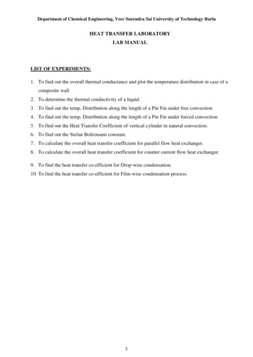
General Overviewaccessories intended for use with the HT10X base unit may also be useable with theHT10XC, but will not have the full functionality of the C versions and mayconsequently require manual intervention.This product manual describes the function of the HT10XC 'Heat Transfer ServiceUnit'.Each of the individual heat transfer accessories (listed above) is supplied with its owninstruction manual. The instruction manual describes the operation of the particularaccessory when used in conjunction with the HT10XC service unit in relation to thosefunctions normally associated with the laboratory technician. It also includes a set ofLaboratory Teaching Exercises designed to cover the theory andexperiments/demonstrations relevant to that accessory. Each exercise includesdetailed instructions on how to record the appropriate readings and whichcalculations to perform to analyse the performance.HT10XC Heat Transfer Service Unit (Connected to thermocouples T1 – T6 and to flow rate sensor Fw)Note: Compatibility of HT10XC with HT14, HT14C, HT16 & HT16CIn February 2006 a component becoming obsolete forced Armfield Ltd to change themains outlet connector (OUTPUT 1) at the rear of the HT10XC console and thecorresponding plug on the mains lead of the HT14, HT14C, HT16 and HT16C. Noother accessories to the HT10XC are affected by this change.An adaptor ‘ADAPTOR1–HT10’ is available from Armfield Ltd that allows a currentHT10XC to be used with an original HT14, HT14C, HT16 or HT16C. If the mains plugon your HT14, HT14C, HT16 or HT16C has exposed pins that do not mate withOUTLET 1 on HT10XC then ‘ADAPTOR1–HT10’ is required.Similarly ‘ADAPTOR2-HT10’ is available from Armfield Ltd that allows an originalHT10XC to be used with a current HT14, HT14C, HT16 or HT16C. If the mains plugon your HT14, HT14C, HT16 or HT16C has pins protected by a shrouded cover thatdoes not mate with OUTLET 1 on HT10XC then ‘ADAPTOR2-HT10’ is required.If you need an adaptor please contact Armfield Ltd specifying if ‘ADAPTOR1-HT10’or ‘ADAPTOR2-HT10’ is required for correct functioning of the equipment.3
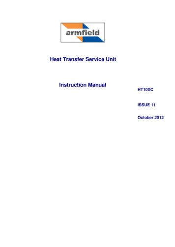
Equipment DiagramsFigure 1: Front View of HT10XC Heat Transfer Service UnitFigure 2: Rear View of HT10XC Heat Transfer Service Unit4
Important Safety InformationIntroductionAll practical work areas and laboratories should be covered by local safetyregulations which must be followed at all times.It is the responsibility of the owner to ensure that all users are made aware ofrelevant local regulations, and that the apparatus is operated in accordance withthose regulations. If requested then Armfield can supply a typical set of standardlaboratory safety rules, but these are guidelines only and should be modified asrequired. Supervision of users should be provided whenever appropriate.Your HT10XC Heat Transfer Service Unit has been designed to be safe in usewhen installed, operated and maintained in accordance with the instructions in thismanual. As with any piece of sophisticated equipment, dangers exist if the equipmentis misused, mishandled or badly maintained.Electrical SafetyThe equipment described in this Instruction Manual operates from a mains voltageelectrical supply. It must be connected to a supply of the same frequency and voltageas marked on the equipment or the mains lead. If in doubt, consult a qualifiedelectrician or contact Armfield.The equipment must not be operated with any of the panels removed.To give increased operator protection, the unit incorporates a Residual CurrentDevice (RCD), alternatively called an Earth Leakage Circuit Breaker, as an integralpart of this equipment. If through misuse or accident the equipment becomeselectrically dangerous, the RCD will switch off the electrical supply and reduce theseverity of any electric shock received by an operator to a level which, under normalcircumstances, will not cause injury to that person.At least once each month, check that the RCD is operating correctly by pressing theTEST button. The circuit breaker MUST trip when the button is pressed. Failure totrip means that the operator is not protected and the equipment must be checked andrepaired by a competent electrician before it is used.5
DescriptionWhere necessary, refer to the drawings in the Equipment Diagrams section.OverviewThe service unit is housed in a robust steel enclosure and designed for use on abench or table.It provides two outputs to the accessories:A stabilised, variable low voltage DC supply to the heater of the heat transferaccessory under evaluation. A variable output (Auxiliary Output) to drive other functions (accessorydependant). This auxiliary output takes two forms, a 0-5V signal and a 24Vpulse width modulated signal. Either of these signals can be used asappropriate by the Heat Transfer Accessory.The Service Unit also incorporates the necessary instrumentation to measure thevariables associated with heat transfer, namely: Temperatures Heater voltage Heater current Heat radiated Light radiated Air velocity Cooling water flowrateModes of OperationRefer to Figure 1.Manual ModeIn manual mode, the outputs listed above are under control of potentiometers on thefront panel of the unit. A ten turn potentiometer (3) controls the heater voltage, and aone turn potentiometer (15) controls the auxiliary output.Manual mode is entered whenever the standby switch (1) is ON, and theManual/Remote switch (2) is in ManualThe outputs from the accessory being used are shown on the front panel displays.One display is used for the ten temperature inputs, and a selector switch is used tochoose the appropriate input. Similarly, all the other inputs are displayed on the otherdisplay, and a selector switch used to choose the input being displayed.Remote ModeIn remote mode the two outputs to the accessories are controlled by the computer, orother external device. As the heater output is capable of providing high currents, and6
Descriptionproducing high temperatures in the accessories, a number of safeguards have beenincorporated to ensure operator and equipment safety in event of a computer failure.To enter remote mode, the following conditions need to be met: Off/Standby switch in Standby and Manual/Remote switch in remote A series of regular ‘Watchdog’ pulses on the watchdog inputThe unit can be then powered up fully by setting the ‘Power On’ bit on the interface.Note: in the event of a failure of the controlling device, e.g. a software ‘crash’, thewatchdog pulses will stop and after a few seconds the HT10XC will switch itself backinto the Standby condition.In remote mode the sensor readings are usually displayed on the controlling orremote computers according to the software being used. However, the front paneldisplays described in Manual mode are still active in Remote mode.Front of Service UnitRefer to Figure 1.The following facilities are provided on the front panel of the service unit:A mains standby switch (1), located on the front of the service unit allows the serviceunit to be turned off totally, or enabled into Standby Mode. All of the individualelectrical circuits inside the enclosure are disabled when switched off.The Manual/Remote switch (2) defines whether the unit is to be operated under FrontPanel Control, or under Computer Control, as described above. Note: the front paneldisplays and selector switches are functional under both modes of operation.The variable DC voltage supplied to the heat transfer accessory, via socket OUTPUT2 at the rear of the service unit, is adjusted using the multi-turn potentiometer (3)marked VOLTAGE CONTROL. The range of the output voltage is continuouslyadjustable from 0 Volts to 24 Volts DC using the multi-turn potentiometer. Theselector switch (2), adjacent to the potentiometer, should be set to the MANUALposition to allow adjustment using the potentiometer. The selector switch is only setto the REMOTE position if the voltage is to be controlled from an external signal viathe USB Port connector (4).The actual voltage supplied can be monitored using the top panel meter (5) when themeasurement selector switch (6) is set to position V. The readout is calibrateddirectly in Volts with a range of 0 to 24 VDC and a resolution of 0.1 Volts.Similarly the current can be monitored when the selector switch (6) is set to positionI. The readout is calibrated directly in Amps with a range of 0 - 9 A and a resolution of0.01 A.Other relevant parameters on the heat transfer accessories can be measured asfollows:Thermal radiation RA radiometer is incorporated on the HT13 to measure the thermal radiation. Thisinstrument is connected to the socket marked R (7) on the front of the service unit.7
Armfield Instruction ManualThe thermal radiation is read on the top panel meter (5) when the measurementselector switch (6) is set to position R.The thermal radiation is indicated directly in units of Watts/metre2 over the range 0 333 W/m2 with a resolution of 1 W/m2.A zero potentiometer (8) to the left of the radiometer socket allows any offset in thereading from the radiometer to be corrected.Light illumination LA light sensor is incorporated on the HT13 to measure the light illumination. Thisinstrument is connected to the socket marked L (9) on the front of the service unit.The light illumination is read on the top panel meter (5) when the measurementselector switch (6) is set to position L.The light illumination is indicated directly in units of Lux over the range 0 - 234 Luxwith a resolution of 1 Lux.Air Velocity UaA vane type anemometer is incorporated on the HT14, HT14C, HT16 and HT16C tomeasure the velocity of the air passing through the duct. This instrument isconnected to the socket marked Ua (10) on the front of the service unit. The airvelocity is read on the top panel meter (5) when the measurement selector switch (6)is set to position Ua. The air velocity is indicated directly in units of metres/secondover the range 0 - 10 m/s with a resolution of 0.1 m/s.Cooling Water Flowrate FwA cooling water flow sensor is incorporated into the HT11C and the HT12C. It is alsoavailable as an optional accessory with the HT11 and HT12. The sensor isconnected to the socket marked Fw (11) on the front of the service unit. The flow ofcooling water is read on the top panel meter (5) when the selector switch (6) is set toposition Fw.The flowrate is indicated directly in units of litres/min over the range 0 - 1.50 l/minwith a resolution of 0.01 l/min.Temperatures T1 - T10Temperatures on the various heat transfer accessories are measured using up to 10type K thermocouples installed in appropriate tappings on the accessory(thermocouples are supplied with the accessory). Each thermocouple lead isnumbered to allow connection to the appropriate thermocouple socket (12) at thebottom of the front panel on the service unit.The required temperature reading is selected via a switch (13) and displayed on theadjacent panel meter (14). Temperature readings are displayed directly on the meterin units of C.Thermocouples T1 - T9 are connected using miniature plugs/sockets. Readings arein the range 0 to 133 C with a resolution of 0.1 C.Thermocouple T10 is connected using standard plugs/sockets. Readings are in therange 0 to 600 C with a resolution of 1 C. (The sockets are polarised by size toprevent high temperature thermocouples from being connected to low temperaturechannels.)8
DescriptionAuxiliary DriveThe Auxiliary drive potentiometer (15) controls the output to the cooling water flowcontrol valve (HT11C and HT12C) or the air flow control (HT14C and HT16C). Theoutput percentage is read on the top panel meter (5) when the selector switch (6) isset to position Aux. The relevant cable (to the flow control valve or fan) should beconnected to the socket marked AUXILARY OUTPUT on the back of the HT10XCconsole. On the HT16C this cable connection also allows computer control of theradiation shield.USB PortThis is a USB socket (4) on the right hand side of the front panel. It allows all of thetemperatures and other measurements to be connected simultaneously to a PC. Italso allows the PC software to control the Heater voltage directly, together withanother input (use may vary on different accessories).Educational and Data Logging Software is available for all of the HT10XC range ofHeat Transfer equipment.Other interfaces could also be used with this I/O Port. Full details of the signals andscaling are given in the USB Port Channels Section.Rear of Service UnitPlease refer to Figure 2.The following facilities are provided on the rear panel of the service unit:The Residual Current Circuit Breaker (16) is a device for the protection of personnelin the event of an electrical fault or short to earth. All electrical circuits inside theservice un
The following heat transfer accessories are available for use under manual control using the control console: HT11 Linear heat conduction . HT12 Radial heat conduction . HT13 Laws of radiant heat transfer and radiant heat exchange . HT14 Combined convection and