Transcription
LABORATORY MANNUALHEAT TRANSFER LABME-316-FBRCM College of Engineering & TechnologyBahal0
E- 316 FL-T-P3HEAT TRANSFER LAB.Sessional : 50 Marks Practical : 50 MarksTotal : 100 MarksDuration of Exam : 3Hrs.List of Experiments:1.2.3.4.To determine the thermal conductivity of a metallic rod.To determine the thermal conductivity of an insulating power.To determine the thermal conductivity of a solid by the guarded hot plate method.To find the effectiveness of a pin fin in a rectangular duct natural convectivecondition and plot temperature distribution along its length.5. To find the effectiveness of a pin fin in a rectangular duct under forced convectiveand plot temperature distribution along its length.6. To determine the surface heat transfer coefficient for a heated vertical tube undernatural convection and plot the variation of local heat transfer coefficient along thelength of the tube. Also compare the results with those of the correlation.7. To determine average heat transfer coefficient for a externally heated horizontalpipe under forced convection & plot Reynolds and Nusselt numbers along thelength of pipe. Also compare the results with those of the correlations.8. To measure the emmisivity of the gray body (plate) at different temperature andplot the variation of emmisivity with surface temperature.9. To find overall heat transfer coefficient and effectiveness of a heat exchange underparallel and counter flow conditions. Also plot the temperature distribution in boththe cases along the length of heat of heat exchanger.10. To verify the Stefen-Boltzmann constant for thermal radiation.11. To demonstrate the super thermal conducting heat pipe and compare its workingwith that of the best conductor i.e. copper pipe. Also plot temperature variationalong the length with time or three pipes.12. To study the two phases heat transfer unit.13. To determine the water side overall heat transfer coefficient on a cross-flow heatexchanger.14. Design of Heat exchanger using CAD and verification using thermal analysispackage eg. I-Deas etc.Note:1. At least ten experiments are to be performed in the semester.2. At least seven experiments should be performed from the above list. Remaining threeexperiments may either be performed from the above list or designed & set by the concernedinstitute as per the scope of the syllabus.1
BRCM COLLEGE OFENGINEERING & TECHNOLOGYBAHAL, BHIWANILabManualExp. TitleTHERMAL CONDUCTIVITY OF METAL RODEXP. NO. 1H. T. LabSemester-6thPage No. 2-6Aim :- To determine thermal conductivity of metal rod.INTRODUCTION:Thermal conductivity is the physical property of the material denoting the ease with whicha particular substance can accomplish the transmission of thermal energy by molecularmotion.Thermal conductivity of a material is found to depend on the chemical composition of thesubstance or substances of which it is a composed, the phase (i.e. gas, liquid or solid) inwhich it exists, its crystalline structure if a solid, the temperature and pressure to which it issubjected, and whether or not it is a homogeneous material.Table 1 – Lists the values of thermal conductivity of some common metal:SOLID’S (Metal)Thermal ConductivityStatePure Copper38020 degreeBrass110- - do - -Steel (0.5%C)54- - do - -S. S.17- - do --W/m CMechanism of Thermal Energy Conduction in Metals:Thermal energy may be conducted in solids by two modes:1. Lattice Vibration.2. Transport by free electrons.Thermal energy can be conducted in solids by free electrons and by lattice vibrations.Large numbers of free electrons move about in the lattice structure of the material in goodconductors. These electrons carry thermal energy from higher temperature region to lowertemp. region, in a similar way they transport electric charge. Infact, these electrons arefrequently referred as electron gas .energy may also be transferred as vibrational energy inthe lattice structure of the material .in general, however, this mode of energy transfer is not2
as large as electron transport and hence ,good electrical conductors are always good heatconductors, e.g copper ,silver etc.However, with increase in temp., lattice vibrations come in the way of transport by freeelectrons and for most the metals thermal conductivity decreases with increase in temp.electrons transport and it is for this reason that good electrical conductors are almost always goodheat conductor viz. Copper, Aluminium and silver. With increase in the temperature, however theincreased lattice vibrations come in the way of the transport by free electrons for most of the puremetals the thermal conductivity y decreases with increase in the temperature.APPARATUS:The experimental set up consists of the metal bar, one end of which is heated by anelectric heater while the other end of the bar projects inside the cooling water jacket.The middle portion of the bar is surrounded by a cylindrical shell filled with theasbestos insulating powder. The temperature of the bar is measured at eight differentsections while the radial temperature distribution is measured by separatethermocouples at two different sections in the insulating shell.The heater is provided with a dimmerstat for controlling the heat input. Water underconstant heat condition is circulated through the jacket and its flow rate andtemperature rise are noted.SPECIFICATION: Metal bar – Copper, 25 mm O.D., approx. 430 mm long with insulation shell along the lengthand water cooled heat sink at the other end. Test length of the bar – 240 mm. Thermocouples – Chromel /alumel, 10 nos. Band Nichrome heater to heat the bar. Dimmerstat to control the heat input – 2A, 230 V. Voltmeter and Ammeter to measure the heater input. Multichannel Digital temperature indicator, 0.1 C least count, 0-200 C with channel selectorswitch. Measuring flask to measure water flow.EXPERIMANTAL PROCEDURE: Start the electric supply. Start heating the bar by adjusting the heater input to, say, 80 volts or 100 volts. Start cooling water supply through the heat sink and adjust it around 350-400 cc perminute. Bar temperature will start rising. Go on checking the temperature at time intervals of 5minutes. When all the temperatures remain steady, note down all the observations and complete theobservation table.3
OBSERVATION TABLE:Sr.No.Test Bar Tmperature CT1T2T3T4T5T6T7T8ShellTemp. CWaterTemp. CT9T11T10Water Flow RateLitr/Sec.T12Using the temperatures of the bar at various points, plot the temperature distribution alongthe length of the bar and determine the slopes of the graph ( i.e. temperature drop per unitlength ) dT/dx at the sections AA, BB, CC as shown in figure.( Note : As the value of temperature goes on decreasing along the length of the bar,the value of slope dT/dx is negative.)Heat is flowing through the bar from heater end to water heat sink. When steady state isreached, heat passing through the section CC of the bar is heat taken by water.4
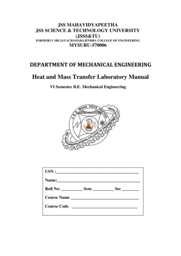
Schematic Diagram:1) Heat passing through section CCQcc m. Cp . T wattsWhere ,m mass flow rate of cooling water, Kg/sCp specific heat of water 4180 J/Kg C T (Water outlet temp.) – (Water inlet temp.) CNow, Qcc - Kcc [ dT/dx] . AccA Cross sectional area of the bar 0.00049 m2 W/ m CKcc 2) Heat passing through section BBQbb Qcc Radial heat loss between CC & BB Qcc2π. K L1 (T6 - T10) Loge (ro / ri)Where,k Thermal conductivity of insulation 0.35 W/m CL1 Length of insulation cylinder 0.060 mro outer radius 0.105 mri inner radiusQbb - Kbb [dT/dx]bb .A5
Kbb . W/m C3) Similarly, heat passing through section AAQaa Qbb Radial heat loss between BB & AA Qbb2π. K L2 . (T3 - T9) Loge (ro / ri)WhereL2 0.090 mQaa - Kaa [dT/dx]aa .AKaa . W/m CConclusion:1) Thermal conductivity of metal rod is found out to be ---------------6
BRCM COLLEGE OFENGINEERING & TECHNOLOGYBAHAL, BHIWANILabManualExp. TitleTHERMAL CONDUCTIVITY OF INSULATINGPOWDEREXP. NO. 2H. T. LabSemester-6thPage No.7-10Aim: To determine the thermal conductivity of an insulating power.INTRODUCTIONConduction of heat is flow of heat which occurs due to exchange of energy from onemolecule to another without appreciable motion of molecules. In any heating process, heatis flowing outwards from heat generation point. In order to reduce losses heat, varioustypes of insulation’s are used in practice. Various powders e.g. asbestos powder, plaster ofparis etc, are also used for heat insulation. In order to determine the appropriate thicknessof insulation, knowledge of thermal conductivity material is essential. The unit enables todetermine the thermal conductivity of insulating powders, using ‘sphere in sphere’ method.APPARATUSThe apparatus consists of a smaller (inner) sphere, inside which is fitted a mica electricheater. Smaller sphere is fitted at the center of outer sphere. The insulating powder, whosethermal conductivity is to be determined, is fitted in the gap between the two spheres. Theheat generated by the heater flows through the powder to the outer sphere. The outer sphereloses heat to atmosphere. The input to the heater is controlled by a dimmerstat and ismeasured on voltmeter and ammeter. Four thermocouples are provided on the outer surfaceof inner sphere and six thermocouples are on the inner surface of outer sphere, which areconnected to multichannel digital temperature indicator. Average of outer & inner spheretemperatures give the temperature difference across the layer of powder.SPECIFICATION: INNER SPHERE – 100 mm O.D., halved construction.OUTER SPHERE – 200 mm I.D., halved construction.HEATER – Mica flat heater, fitted inside inner sphere.CONTROLS – 1) Main Switch – 30 A , DPDT Switch2) Dimmerstat – 0-230 volts, 2A capacity MEASUREMENTS1) Voltmeter – 0-200 volts7
2) Ammeter- 0-1 Amp.3) Multichannel digital temperature indicator, calibrated for cr/Al thermocouples.PROCEDURE: Keep dimmerstat knob at ZERO position and switch ON the equipment. Slowly rotate the dimmerstat knob, so that voltage is applied across the heater. Letthe temperature rise. Wait until steady state is reached. Note down the temperatures and input of heater in terms of volts and current. Repeat the procedure for different heat input.OBSERVATIONS:Sr. No.TEMPERATURES OCT1 T2 T3 T4 T5 T6 T7 T8HEATER INPUTT9T10 VoltsAmpsTHEORY :8
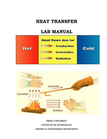
Consider the transfer of heat by conduction through the wall of a hollow sphere formed ofinsulating powder (Ref. fig.)Let,ri radius of inner sphere, mro radius of outer sphere, mTi avg. inner sphere temperature cTo avg. outer sphere temperature cConsider a thin spherical layer of thickness dr at radius r & temperature difference of dTacross the layer. Applying Fourier Law of heat conduction, heat transfer rate,q - k . 4π . [dT/dr]Where, k thermal conductivity of insulating powderqdr - dT4.π.krIntegrating between, ri to ro & Ti to To, we getorQ/4 [1/ri - 1/ro] (Ti –To)4.π.k.ri .ro. (Ti- To)orq (ro – ri)From the measured value of q, Ti and To thermal conductivity of insulating powder can bedetermined as,q (ro - ri)k 4.π.ri.ro.(Ti – To)CALCULATION: Heater input ; q V I watts Avg. inner sphere surface temperatureT1 T2 T3 T4Ti C4 Avg. outer sphere surface temperatureT5 T6 T7 T109
To C6 Inner sphere radius 50 mm 0.05 m Outer sphere radius 100 mm 0.01 mq. (ro – ri)Now, k W/m K4.π.ri.ro. (Ti –To)Ti Toat C2PRECAUTIONS: Operate all the switches and control gently. If thermal conductivity of the powder other than supplied is to be determined, thengently dismantle the outer sphere and remove the powder, taking care that heaterconnections and thermocouples are not disturbed. Earthing is essential for the unit.Schematic Diagram:10
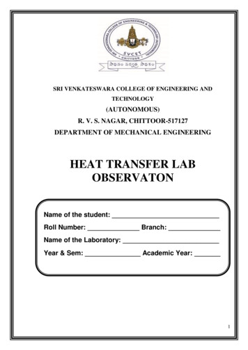
BRCM COLLEGE OFENGINEERING & TECHNOLOGYBAHAL, BHIWANIExp. TitleThermal conductivity of a solid by the guarded hot plate methodH. T. LabSemester-6thLabManualEXP. NO. 3Page No. 11-15Aim: To determine the thermal conductivity of a solid by the guarded hot plate method.GENERAL DESCRIPTION:The apparatus is designed and fabricated according to the Guarded Hot Plate Principle. Theguarded hot plate method has been recognized by scientists and engineers in U.S.A., WestGermany, Scandinavian Countries, USSR and India as most dependable and reproducible forthe measurement of thermal conductivity of insulating materials. It is a steady state absolutemethod suitable for materials which can be laid flat between two parallel plates and can beadopted for loose fill materials which can be filled between such plates.PRINCIPLES OF THE GUARDED HOT PLATE METHOD:The essential parts- the hot plate, the cold plates, the heater assembly, thermocouples and thespecimens in position are shown in the same figure.For the measurement of thermal conductivity (k) what is required is to have a onedimensional heat flow through the flat specimen, an arrangement for maintaining its faces atconstant temperature and some metering method to measure the heat flow through a knownarea. To eliminate the distortion caused by edge losses in unidirectional heat flow, the centralplate is surrounded by a guard which is separately heated. Temperatures are measured bycalibrated thermocouples either attached to the specimens at the hot and cold faces. Twospecimens are used to ensure that all the heat comes not through the specimen only. Knowingthe heat input to the central plate heater, the temperature difference across the specimen, itsthickness and the metering area, one can calculate K of the specimen by the followingformula:qLK 2ATh – TcWhere,W/m C (1)K Thermal conductivity of sample, W/m Cq Heat flow rate in the specimen, WattsA Metering area of the specimen,Th Hot plate temperature, CTc Cold plate temperature, C11
L Thickness of specimen, mIf the specimen thickness are different and the respective hot and col
11. To demonstrate the super thermal conducting heat pipe and compare its working with that of the best conductor i.e. copper pipe. Also plot temperature variation