Transcription
Department of Chemical Engineering, Veer Surendra Sai University of Technology BurlaHEAT TRANSFER LABORATORYLAB MANUALLIST OF EXPERIMENTS:1. To find out the overall thermal conductance and plot the temperature distribution in case of acomposite wall2. To determine the thermal conductivity of a liquid.3. To find out the temp. Distribution along the length of a Pin Fin under free convection4. To find out the temp. Distribution along the length of a Pin Fin under forced convection5. To find out the Heat Transfer Coefficient of vertical cylinder in natural convection.6. To find out the Stefan Boltzmann constant.7. To calculate the overall heat transfer coefficient for parallel flow heat exchanger.8. To calculate the overall heat transfer coefficient for counter current flow heat exchanger.9. To find the heat transfer co-efficient for Drop-wise condensation.10. To find the heat transfer co-efficient for Film-wise condensation process.1
Department of Chemical Engineering, Veer Surendra Sai University of Technology BurlaEXPERIMENT-1OBJECTIVE: Study of conduction heat transfer in composite wall.AIM:1. To determine total thermal resistance and thermal conductivity of composite wall.2. To calculate thermal conductivity of one material in composite wall.3. To plot the temperature profile along the composite wall.INTRODUCTION:When a temperature gradient exists in a body, there is an energy transfer from the hightemperature region to the low temperature region. Energy is transferred by conduction and heattransfer rate per unit area is proportional to the normal temperature gradient:q T A XWhen the proportionality constant is inserted,q kA T XWhere q is the heat transfer rate and T/ X is the temperature gradient in the direction of heatflow. The positive constant k is called thermal conductivity of the material.THEORY:A direct application of Fourier’s law is the plane wall. Fourier’s equation:q kA T2 T1 XWhere the thermal conductivity is considered constant. The wall thickness is X, and T1and T2 are surface temperatures. If more than one material is present, as in the multiplayerWall, the analysis would proceed as follows:The temperature gradients in the three materials (A, B, C), the heat flow may be writtenq k A A T TA T k B A B k C A C X A X B X C2
Department of Chemical Engineering, Veer Surendra Sai University of Technology BurlaDESCRIPTION:The Apparatus consists of a heater sandwiched between two asbestos sheets. Three slabs ofdifferent material are provided on both sides of heater, which forms a composite structure. Asmall press- frame is provided to ensure the perfect contact between the slabs. A Variac isprovided for varying the input to the heater and measurement of input power is carried out by aDigital Voltmeter & Digital Ammeter. Temperatures Sensors are embedded between inter facesof the slab, to read the temperature at the surface. The experiment can be conducted at variousvalues of power input and calculations can be made accordingly.UTILITIES REQUIRED:1. Electricity Supply: Single Phase, 220 VAC, 50 Hz, 5-15Amp socket with earthconnection.2. Bench Area Required: 1m x 1m.EXPERIMENTAL PROCEDURE:STARTING PROCEDURE:1. Ensure that Mains ON/OFF switch given on the panel is at OFF position &dimmer-stat isat zero position.2. Connect electric supply to the set up.3. Switch ON the Mains ON / OFF switch.4. Set the heater input by the dimmer-stat, voltmeter in the range 40 to 100 V.5. After 1 hour. Note down the reading of voltmeter, ampere meter and temperature sensorsin the observation table after every 10 minutes interval till observing changeinconsecutive readings of temperatures ( 0.2 oC).CLOSING PROCEDURE:1. After experiment is over set the dimmer stat to zero position.2. Switch OFF the Mains ON/OFF switches.3. Switch OFF electric supply to the set up.OBSERVATION & CALCULATIONS:DATA:d 0.25 m3
Department of Chemical Engineering, Veer Surendra Sai University of Technology BurlaX1 0.020 m 20mmX2 0.020m 20 mmX3 0.012m 12mmK1 125w/m K2 1.4w/m K3 ----w/m OBSERVATION TABLE:Sl. TIONS:To plot the temperature profile,Distance010Avg. TempAt distance 0, average temp At distance 10, average temp At distance 20, average temp At distance 45, average temp T1 T2 2 T3 T4 2 T5 T6 2 T7 T8 2Heat supplied by the heater, W 0.86 V I , wattsAmount of Heat Transfer, Q W, watts42045CC
Department of Chemical Engineering, Veer Surendra Sai University of Technology BurlaWhere, A 2 2d ,m4Overall Temp. Difference T T1 T7 T2 T8 2Total thermal resistance of composite wall Rt , oC T o, C m2/WqTotal thickness of wall X X 1 X 2 X 3 , mThermal Conductivity of composite wall K eff Thermal Conductivity of press wood K 3 q X, W/m oC TX3 T X 1 X 2 qkk2 1 , W/m oCNOMENCLATURE:A Area of heat transfer, m2d Diameter, mI Ammeter reading, ampK eff Thermal conductivity of composite wall, W/m oCk1 Thermal conductivity of cast iron, W/m oC.k2 k3 Thermal conductivity of Bakelite, W/m oCQ Amount of heat transfer, Wq Heat flux, W/m2Rt Total thermal resistance of composite wall, oC m2/WΔT Overall temperature difference, oCThermal conductivity of Press wood, W/m oCT1 & T2 Interface temperature of 1ST slab and heater, oCT3 & T4 Interface temperature of 1st and2nd slab, oCT5 & T6 Interface temperature of 2nd and 3rd slab, oCT7 & T8 Top surface temperature of press wood, oCV Voltmeter reading, voltsW Heat supplied by the heater, W5
Department of Chemical Engineering, Veer Surendra Sai University of Technology BurlaΔX Total thickness of wall, mX1 MS Slab thickness, mX2 Bakelite slab thickness, mX3 Press wood thickness, mPRECAUTION1. Use the stabilize A.C. Single phase supply only. The voltage should not very more than volts2. Keep Dimmer stat to zero before start and increase the voltage slowly.3. Keep all the assembly undisturbed.4. Remove air gap between plates by moving hand press gently.5. Operate selector switch of temperature indicator gently.There is a possibility of getting abrupt result if the supply voltage fluctuating or if thesatisfactory steady state condition is not reached.6
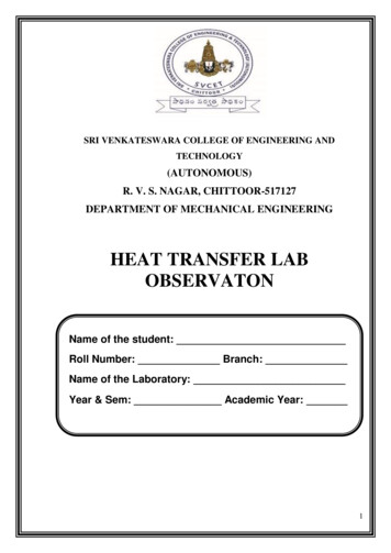
Department of Chemical Engineering, Veer Surendra Sai University of Technology BurlaEXPERIMENT-2OBJECTIVE:Study of heat transfer through liquidAIM:To determine the thermal conductivity of a liquidINTRODUCTION:When temperature gradient exists in a body, there is an energy transfer from the hightemperature region to the low temperature region. Energy is transferred by conduction andheat transfer rate per unit area is proportional to the normal temperature gradient:𝑞 𝑇 𝐴 𝑋When the proportionality constant is inserted,q KA T XWhere q is the heat transfer rate and T X is the temperature gradient in the direction ofheat flow. The positive constant k is called is thermal conductivity of the material.THEORY:For thermal conductivity of liquids using Fourier’s law, the heat flow through theliquid from hot fluid to cold fluid is the heat transfer through conductive fluid medium.Fourier’s equation:q KA X(T1 T2 )Fourier’s law for the case of liquidAt steady state, the average face temperatures are recorded (Th and Tc) along with therate of heat transfer (Q). Knowing, the heat transfer area (Ah) and the thickness of the sample( X) across which the heat transfer takes place, the thermal conductivity of the sample can beCalculated using Fourier’s Law of heat conduction.Q kAh ΔT/ΔX kAh (Th - Tc) / ΔX7
Department of Chemical Engineering, Veer Surendra Sai University of Technology BurlaThqΔxHeat transfer area Ah (area to direction of heat flow)DESCRIPTION:The apparatus is based on well-established “Guarded Hot Plate” method. It is a steadystate absolute method suitable for materials, which can be fixed between two parallel platesand can also be extended to liquids that fill the gap between the plates.The essential components of the set-up are the hot plate, the cold plate, and heater toheat the hot plate, cold water supply for the cold plate, RTD PT-100 Sensors and the liquidspecimen holder.In the set-up, a unidirectional heat flow takes place across the liquid whose two faces aremaintained at different temperatures by the hot plate on one end and by the cold plate at theother end.A heater heats hot plate and voltage to the heater is varied with the help of variac toconduct the experiment on different voltages as well as different heat inputs. Temperatures aremeasured by RTD PT-100 sensors attached at three different places on the hot plate as well ason the cold plate. These sensors are provided on the inner surface facing the liquid sample. Anaverage of these sensor readings are used as Th and Tc at steady state condition.Heat is supplied by an electric heater for which, we have to record the voltmeter reading(V) and ammeter reading (A) after attaining the steady state condition. The temperature of thecold surface is maintained by circulating cold water at high velocity. The gap between hot plateand cold plate forms the liquid cell, in which liquid sample is filled.The depth of the liquid in the direction of flow must be small to ensure the absence ofconvection currents and a liquid sample of high viscosity and density shall further ensure theabsence of convection and the heat transfer can be safely assumed to take place by conductionalone.8
Department of Chemical Engineering, Veer Surendra Sai University of Technology BurlaUTILITIES REQUIRED:Water supply 5 lit/min (approx.)Drain.Electricity Supply: 1 Phase, 220 V AC, 2 Amperes.Table for set-up support (optional)EXPERIMENTAL PROCEDURE:1. Fill the liquid cell with the sample liquid (glycerol) through the inlet port, keeping theapparatus tilted towards upper side so that there is complete removal of air through theoutlet port. Liquid filling should be continued till there is complete removal of air and alsoliquid glycerol comes out of the outlet port. Close the outlet port followed by inlet port.2. Allow cold water to flow through the cold-water inlet.3. Start the electric heater to heat hot plate. Adjust the voltage of hot plate heater in the rangeof 10 to 50 volts.4. Adjust the cold-water flow rate such that there is no appreciable change the outlettemperature of cold water (there should be minimum change).5. Go on recording the thermocouple readings on hot side as well as on cold side, and oncesteady state is achieved (may be after 30-60 min); (steady state is reached when there noappreciable change in the thermocouple readings, 0.1, C), record the three thermocouplereadings (Th1, Th2, Th3 i.e. T1, T2, T3 on Temperature Indicator) on the hot side andthree thermocouple readings (Tc1, Tc2, Tc3 i.e. T4, T5, T6 on Temperature Indicator)on the cold side along with the voltmeter (V) and ammeter (A) readings.6. Stop the electric supply to the heater, and continue with the supply of cold water till thereis decrease in temperature of hot plate (may be for another 30-40 min).7. Open the liquid outlet valve slightly in the downward tilt position and drain the sampleliquid in a receiver, keeping liquid inlet port open.SPECIFICATION:1.Hot Plate9
Department of Chemical Engineering, Veer Surendra Sai University of Technology Burla2.Material brassDiameter 180 mmMaterial AluminumDiameter 180 mmCold Plate3.Sample Liquid depth 18 mm4.Temp. Sensors RTD PT-100 type.Type RTD PT-100 typeQuantity 6 Nos.No. 1 to No. 3 mounted on hot plate.No. 4 to No. 6 mounted on cold plate.5.Digital Temperature indicatorRange 0 C to 199.9 CLeast Count 0.1oC6.Variac 2 Amp, 230VAC7.Digital Voltmeter 0 to 250 Volts8.Digital Ammeter 0 to 2.5 Amp.9.Main Heater Nichrome heater 300 Watt approximate, ringheater mica held between plates 300 watt, topheater held between plates 300 watt, separatedimmer for heaters, volt and current meter, multichannel digital temp indicatorFORMULAE1. Heat input,Q V*I watt10
Department of Chemical Engineering, Veer Surendra Sai University of Technology Burla2. Thermal conductivity of liquid,K Q X, Watt/m CA(Th Tc )OBSERVATIONS & CALCULATIONS:DATA:Effective diameter of plate 0.165 mEffective area of heat transfer, A 0.02139 m2OBSERVATIONS TABLE:Sl. No.VIW Th1Th2Th3TC1TC2TC3Cold water flow rateRecord the following at steady state:Sample liquid:Heat input,Q -------------- wattHot face average temperature,Th (Th1 Th2 Th3) /3Cold face temperature,Tc (Tc1 Tc2 Tc3) / 3Temperature difference,ΔT (Th-Tc)K ------------- W/m CThermal conductivity,NOMENCLATURE:Q Heat supplied by heater, watt.A Heat transfer area, mTh Hot face average temperature, CTc Cold face average temperature, C T Temperature difference, CK Thermal conductivity of liquid, w/m, C211
Department of Chemical Engineering, Veer Surendra Sai University of Technology BurlaΔX Thickness of liquid, mm 18 mmPRECAUTIONS & MAINTENANCE INSTRUCTIONS:1. Use the stabilize A.C. Single Phase supply only.2.Never switch on mains power supply before ensuring that all the ON/OFF switchesgiven on the panel are at OFF position.3. Voltage to heater starts and increases slowly.4. Keep all the assembly undisturbed.5.Never run the apparatus if power supply is less than 180 volts and above than 240volts.6. Operate selector switch of temperature indicator gently.7. Always keep the apparatus free from dust.8. Testing liquid should be fully filled.There is a possibility of getting abrupt result if the supply voltage is fluctuating or if thesatisfactory steady state condition is not reached.TROUBLESHOOTING:1. If electric panel is not showing the input on the mains light. Check the fuse and alsocheck the main supply.2. If D.T.I displays “1” on the screen checks the computer sockets if loose tight it.3. If temperature of any sensor is not displays in D.T.I check the connection and rectifythat.4. Voltmeter showing the voltage given to heater but ampere meter does not. Tight theheater socket & switch if ok it means he
heat flow. The positive constant k is called is thermal conductivity of the material. THEORY: For thermal conductivity of liquids using Fourier’s law, the heat flow