Transcription
JSS MAHAVIDYAPEETHAJSS SCIENCE & TECHNOLOGY UNIVERSITY(JSSS&TU)FORMERLY SRI JAYACHAMARAJENDRA COLLEGE OF ENGINEERINGMYSURU-570006DEPARTMENT OF MECHANICAL ENGINEERINGHeat and Mass Transfer Laboratory ManualVI Semester B.E. Mechanical EngineeringUSN :Name:Roll No: Sem SecCourse NameCourse Code
DEPARTMENT OF MECHANICAL ENGINEERINGVISION OF THE DEPARTMENTDepartment of mechanical engineering is committed to prepare graduates, post graduates andresearch scholars by providing them the best outcome based teaching-learning experience andscholarship enriched with professional ethics.MISSION OF THE DEPARTMENTM-1: Prepare globally acceptable graduates, post graduates and research scholars for theirlifelong learning in Mechanical Engineering, Maintenance Engineering andEngineering Management.M-2: Develop futuristic perspective in Research towards Science, Mechanical EngineeringMaintenance Engineering and Engineering Management.M-3: Establish collaborations with Industrial and Research organizations to form strategicand meaningful partnerships.PROGRAM SPECIFIC OUTCOMES (PSOs)PSO1PSO2PSO3Apply modern tools and skills in design and manufacturing to solve real worldproblems.Apply managerial concepts and principles of management and drive globaleconomic growth.Apply thermal, fluid and materials fundamental knowledge and solve problemconcerning environmental issues.PROGRAM EDUCATIONAL OBJECTIVES (PEOS)PEO1: To apply industrial manufacturing design system tools and necessary skills in thefield of mechanical engineering in solving problems of the society.PEO2: To apply principles of management and managerial concepts to enhance globaleconomic growth.PEO3: To apply thermal, fluid and materials engineering concepts in solving problemsconcerning environmental pollution and fossil fuel depletion and work towardsalternatives.
PROGRAM OUTCOMES (POS)PO1Engineering knowledge: Apply the knowledge of mathematics, science,engineering fundamentals, and an engineering specialization to the solution ofcomplex engineering problems.PO2Problem analysis: Identify, formulate, review research literature, and analyzecomplex engineering problems reaching substantiated conclusions using firstprinciples of mathematics, natural sciences, and engineering sciences.PO3Design/development of solutions: Design solutions for complex engineeringproblems and design system components or processes that meet the specifiedneeds with appropriate consideration for the public health and safety, and thecultural, societal, and environmental considerations.PO4Conduct investigations of complex problems: Use research-based knowledgeand research methods including design of experiments, analysis and interpretationof data, and synthesis of the information to provide valid conclusions.PO5Modern tool usage: Create, select, and apply appropriate techniques, resources,and modern engineering and IT tools including prediction and modeling tocomplex engineering activities with an understanding of the limitations.PO6The engineer and society: Apply reasoning informed by the contextualknowledge to assess societal, health, safety, legal and cultural issues and theconsequent responsibilities relevant to the professional engineering practice.PO7Environment and sustainability: Understand the impact of the professionalengineering solutions in societal and environmental contexts, and demonstrate theknowledge of, and need for sustainable development.PO8Ethics: Apply ethical principles and commit to professional ethics andresponsibilities and norms of the engineering practice.PO9Individual and team work: Function effectively as an individual, and as amember or leader in diverse teams, and in multidisciplinary settings.PO10 Communication: Communicate effectively on complex engineering activitieswith the engineering community and with society at large, such as, being able tocomprehend and write effective reports and design documentation, make effectivepresentations, and give and receive clear instructions.PO11 Project management and finance: Demonstrate knowledge and understanding ofthe engineering and management principles and apply these to one‟s own work, asa member and leader in a team, to manage projects and in multidisciplinaryenvironments.PO12 Life-long learning: Recognize the need for, and have the preparation and abilityto engage in independent and life-long learning in the broadest context oftechnological change.
SYLLABUSHEAT & MASS TRANSFER LABORATORYSubject CodeNo. of Contact Hours /Week No. of Contact HoursTotal: ME68L: 03: 39No. of Credits: 0-0-1.5CIE Marks: 50COURSE OBJECTIVES:1.To provide students with the necessary skills to conduct experiments on conduction andconvection of heat; collect data, perform analysis and interpret results to draw validconclusions through standard test procedures2.To determine thermal properties and performance of radiation heat transfer, heatexchanger, vapour compression refrigerator and air conditionerCOURSE CONTENTPART – A1.2.3.4.5.6.7.Determination of Thermal Conductivity of Metal Rod.Determination of Thermal Conductivity of LiquidDetermination of Thermal Conductivity of Insulating MaterialDetermination of Overall Heat Transfer Coefficient of a Composite wall.Determination of Effectiveness on a Metallic fin.Determination of Heat Transfer Coefficient in a free Convection on a vertical tube.Determination of Heat Transfer Coefficient in a Forced Convention Flow through a Pipe.PART – B8.9.10.11.Determination of Critical Heat Flux.Determination of Emissivity of a Surface.Determination of Stefan Boltzman Constant.Determination of LMDT and Effectiveness in a Parallel Flow and Counter Flow HeatExchangers.12. Performance Test on Vapour Compression Refrigeration.13. Performance Test on a Air – ConditionerCOURSE OUTCOMES:Upon completion of this course, students should be able to:CO1 Conduct experiments on conduction, convection and radiation of heat; collect data,perform analysis and interpret results to draw valid conclusions through standard testproceduresCO2 Determine thermal properties and performance of heat exchanger, vapour compressionrefrigerator and air conditioner
Heat and Mass Transfer Laboratory mal Conductivity of Metal RodThermal Conductivity of LiquidThermal Conductivity of Insulating MaterialDetermination of Overall Heat Transfer Coefficient of aComposite wall.Heat Transfer Coefficient in Natural ConvectionHeat Transfer Coefficient in Forced ConventionEffectiveness on a Pin finCritical Heat FluxEmissivity of SurfaceStefan Boltzman ConstantEffectiveness of Heat ExchangersVapour Compression RefrigerationAir – ConditionerPage No.3812151923273035394347491
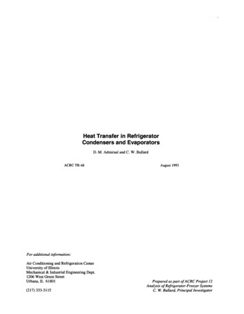
Laboratory Layout3.8 m11.7 m1. Critical heat flux apparatus3. Thermal conductivity of metal rod5. Thermal conductivity of liquid7. Air conditioning test rig9. Heat transfer from Pin-Fin unit11. Thermal conductivity of composite wall13. Refrigeration test rig2. Stefan-Boltzmann unit4. Emissivity measurement unit6. Parallel and counter flow heat exchanger8. Natural convection heat transfer10. Forced convection heat transfer12. Thermal conductivity of insulating powder14. Thermal conductivity of insulating material2
EXPERIMENT NO.1THERMAL CONDUCTIVITY OF METAL RODAIM:To determine the thermal conductivity of metal rod (Aluminium).INTRODUCTION:Conduction is a process of heat transfer through solids, liquids and gases. When thetemperature gradient exists in a body, experience has shown that there is a transfer of heatfrom high temperature region to the low temperature region. The heat transfer rate per unit isproportional to the temperature gradient in the direction of heat flow:Q/A α ( T/ X)Where „Q‟ is the heat transfer in (watts), „A‟ is the area of heat transfer (m2), T/ X is thetemperature gradient in the direction of heat flow (⁰C/m). Where the proportionality constantis a property of a material and is known as thermal conductivity.Q/A -k ( T/ X)The positive constant „k‟ is called the co-efficient of thermal conductivity of material. Thenegative sign indicates that heat transfer takes place in the direction of decreasingtemperature. Co-efficient of thermal conductivity has the units of W/m⁰C. Note that heat flowrate is involved and the numerical value of the co-efficient of thermal conductivity indicateshow fast heat will flow in a given material.Thermal conductivity co-efficient is a physical property of the material. Although it isfairly constant in narrow temperature range, it varies over a wide temperature range. Metals,which are good conductors of heat, have high values of co-efficient of thermal conductivity;for example 385 W/m⁰C for copper. Insulating material have low values of co-efficient ofthermal conductivity for example 0.048 W/m⁰C for fibre insulating board. In any conductionheat transfer problem, it is essential to have the knowledge of co-efficient of thermalconductivity of the material involved in the heat transfer process. This setup has beendesigned to measure the temperature gradient along the length of the aluminium rod and todetermine it‟s co-efficient of thermal conductivity.3
APPARATUS:Fig.1 shows the schematic representation of experimental setup. It consists of analuminium rod, one end of which is heated by an electric heater and other end projects insidesthe cooling water jacket. The middle portion of the rod is thermally insulated from thesurroundings using asbestos rope. The temperature of the rod is measured at four differentlocations along its length. Following are the important features of the experimental setup.a. Aluminium rod lengthDiameter: 500 mm (effective): 40 mmNo. of thermocouples mountedalong the length: 6 (at the intervals of 50 mm)b. Band heaterc. Thermal insulation covering the aluminum rod to reduce those losses to thesurroundings.d. Cooling water jacket with water supply connections and thermocouples at both inletand outlet.e. Heat controller or regulator to vary the input power to the heaterf. Rotameter to measure water flow rater in the cooling water jacket.g. Thermocouples to measure the temperature at 1, 2, 3, 4, 5 & 6 along the length of thealuminum rod and 7 & 8 to measure temperature at inlet and outlet of water jacket.h. Digital temperature indicator and channel selector.OPERATIONAL PROCEDURE:a. Switch on the mains and the console.b. Open the valve at the inlet of the cooling water jacket and maintain constant waterflow rate in the rotometer.c. Switch on the heater.d. Set the heat controller or regulator which adjusts power input to heater.e. Wait till the temperatures T1 to T6 are constant with time that is steady state isreached.f. Read the temperatures T1 to T6 on the metal rod using the channel selector and digitaltemperature indicator.4
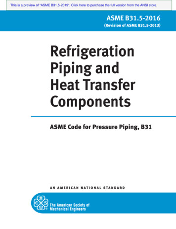
g. Read inlet and outlet water temperatures (T7 and T8) of the cooling water jacket.h. Measure the cooling water flow rate in the rotometer.i. Using the measured temperatures and water flow rate, the temperature gradient alongthe length of the aluminium rod and co-efficient of thermal conductivity of aluminiumare calculated using the procedure given below.j. Repeat the experiment for different heat input and mass flow rate of water.WORKING PRINCIPLE:5050505050T7(water inlet)T150T2T3T4T5T6T8(water outlet)HeaterFig. 1 Schematic diagram of Experimental SetupFig. 1 shows the schematic of the heat transfer process. The heat balance equation isgiven by:Qi Q0 Ql . (1)WhereQi Input heat flow rate from the heater to the aluminum rodQ0 Output heat flow rate from the aluminum rod Heat flow rate absorbed by water in the cooling water jacketQ1 Heat loss from the rod to the surroundings through thermal insulation, assumedto be zero.We can assume the Q1 0, because of good thermal insulation.Therefore, we get the heat flow rate through the rod as:Qi Q0 mCp Tw . (2) Tw Rise in temperature of the cooling water (T7-T8) in ⁰C5
m water flow rate in kg/s in the cooling water jacket fromrotometer.Cp specific heat of water, 4.2 kJ/kg K.Determination of temperature gradient ( t/ x) along the length of aluminumrod:From the measured temperatures T1, T2, T3, T4, T5, and T6, surface temperaturedistributions along the length of the aluminium rod can be determined by plotting agraph of distance along the rod on the x axis and temperature on the y axis as shownin the Fig.2Fig.2: Plot of temperature v/s distanceThus, the temperature gradient t/ x at the center of the aluminium rod in ⁰C/m canbe determined from the slope of the curve (by drawing a tangent).Determination of co-efficient of thermal conductivity:The heat conduction equation is given byQ -kA( t/ x) . (3)Where,Q Heat flow rate through the aluminium rod in wattsK Co-efficient of thermal conductivity of aluminium, W/mKA d2 /4 Area of heat transfer in m2D Diameter of the aluminium rod 40 mm 0.04 mFrom eqs (2) & (3), we getk m Cp Tw / [A ( t/ x)]The co-efficient of thermal conductivity (k) can be obtained by substituting themeasured values of m, Tw, T/ X, A and Cp.6
The above analysis assumes that the heat loss from the aluminium rod is negligibledue to thermal insulation.TABULAR COLUMN:SlnoHeat inputV A QThermocouple readingin 0CCoolingwaterTemperatureTTTTTT123456T7T8Mass erature gradientThermalconductivitydt/dxKk)(W/mThe typical value of the co-efficient of thermal conductivity of aluminium is 200-360W/m K. The difference between the actual and measured values of „k‟ is due to theheat losses through the thermal insulation and may be acceptable as in any heattransfer experiment.The experiment can be repeated for different water flow rate and heat input.The values of „k‟ obtained are tabulated.Result: Thermal conductivity of aluminum rod isW/m C.7
EXPERIMENT NO.2THERMAL CONDUCTIVITY OF LIQUIDAIM:To determine the thermal conductivity of given liquid.INTRODUCTION:Heat is tr
j. Repeat the experiment for different heat input and mass flow rate of water. WORKING PRINCIPLE: 50 50 50 50 50 50 T7 T8 (water inlet) (water outlet) He ater Fig. 1