Transcription
Supporting InformationforContinuous parallel ESI-MS analysis of reactions carriedout in a bespoke 3D printed deviceJennifer S. Mathieson, Mali H. Rosnes, Victor Sans, Philip J. Kitson and LeroyCronin*Address: School of Chemistry, University of Glasgow, G12 8QQ, United KingdomEmail: Leroy Cronin* - Lee.Cronin@glasgow.ac.uk* Corresponding authorAdditional experimental dataTable of Content1General Experimental Remarks.S21.1 Design Software. .S21.2 Device Setup .S21.3 ESI-MS S42ESI-MS Data .S5S1
1 General experimental remarksAll chemical reagents and solvents were purchased from Sigma Aldrich and usedwithout further purification.1.1 Design software: The 3D-printed device used in this work was designed on thefreely distributed 3D CAD software Autodesk123D (http://www.123dapp.com/)although any 3D modelling/CAD software with the ability to export models in an STLfile (Supporting Information File 2) format would suffice for this, and there are anumber of suitable alternative free/open source candidates available on the internet.The device design was exported as an STL file (available from the authors), whichwas then interpreted by Bits from Bytes Axon 2 software, which produces a 3Dprinter instruction file (BFB file), which was subsequently transferred to the3DTouchTM 3D printer. The printing was conducted in a layer-by-layer fashion by the3DTouchTM printer, and the device was printed using polypropylene (PP) and fittedwith standard PTFE 1/16” (1.6 mm) OD tubing and standard screw connectors. Theinlet tubing was subsequently connected to the pumps, whilst the outlet was fittedwith a T-device for dilution and a polyether ether ketone (PEEK) microsplitter valvewith PEEK tubing to control the flow to the ESI-MS.1.2 Device setup: The overall dimensions of the device are 46.5 80 mm. It takesfive hours to print, and the inner path of the device is about 1.5 mm in diameter. Thetotal internal capacity of the device is roughly 0.65 mL, and the actual reactioncapacity is about 0.57 mL. The printed device weighs about 20 g and can be valuedat approximately US 0.40 ( 0.30). The total cost of the PEEK accessories wasUS 230 ( 180) and the Tricontinent C-3000 syringe pumps with the associatedS2
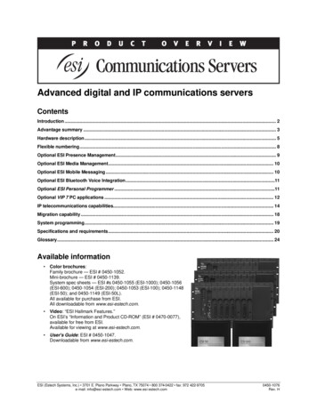
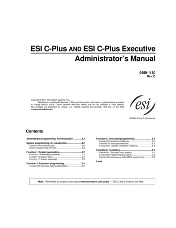
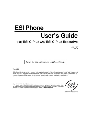
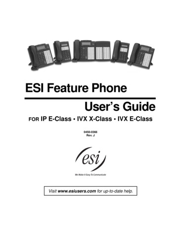
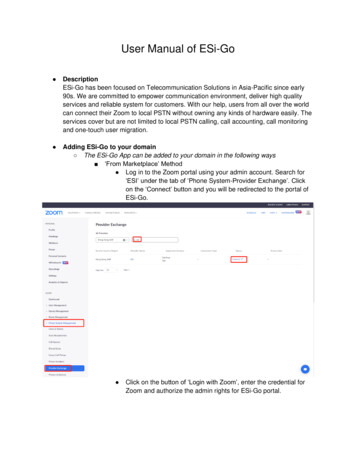
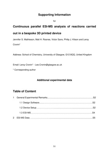
hardware cost US 1000 ( 770) per pump. Therefore the total cost wasapproximately US 4200 ( 3300).All solutions were pumped by means of Tricontinent C-3000 syringe pumps equippedwith 1 mL syringes for the starting materials, and with a 5 mL syringe for the dilutionstep. An in-house-developed LabView application was employed to program thepumps to deliver the desired flow rates.Figure S1: The device setup, where the numbers denote the four pumps used,where pump A, B and C have 1 mL syringes, and pump D has a 5 mL syringe. Thepale blue channels represent the tubing, the T denotes the T-piece where the dilutiontakes place, whilst M denotes the PEEK microsplitter valve, which splits the flow sothat only the required amount will reach the ESI-MS. Check-valves were fittedbetween the pumps and inlet A–C, about 1.5 cm from the device, to avoid backflowand diffusion when the pumps were idle.As seen in Figure S2, it is evident that there is no backflow or diffusion issue for inletC when only pumps A and B are moving as the solution is still colourless between theinlet and the check-valve for this inlet. On closer inspection it can be seen that a bluearea is in front of the purple area within the reactor device. This is because pump AS3
runs twice as fast as pump B, and therefore the area at the front is only MethyleneBlue. To avoid this problem during our experiments we ignored the first two runs,allowing the device to be properly filled first.Figure S2: A photograph of the device with Methylene blue in inlet A, Rhodamine Bin inlet B, and pump C idle. It can be seen how the blue and red colours mix from theresulting purple colour, behind the blue solution. The first two runs are ignored toavoid the initial solution coming from only the fastest pump.1.3 ESI-MS: The experiments were carried out at 180 C at concentrations of thecomplex in the region of 10 4 and 10 5 mol·L 1 in methanol by using a Bruker MaXisImpact instrument. The calibration solution used was Agilent ESI-L low concentrationtuning mix solution, Part No. G1969-85000, enabling calibration betweenapproximately 50 m/z and 2000 m/z. Samples were dissolved in CH3OH (10 4 M) andintroduced into the MS at a dry gas temperature of 180 C. The ion polarity for all MSscans recorded was positive, with the voltage of the capillary tip set at 4500 V, endplate offset at 500 V, funnel 1 RF at 400 Vpp and funnel 2 RF at 400 Vpp, hexapoleRF at 200 Vpp, ion energy 5.0 eV, collision energy at 5 eV, collision cell RF at 200Vpp, transfer time at 100.0 µs, and the pre-pulse storage time at 10.0 µs. Eachspectrum was collected for 100 min.S4
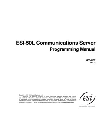
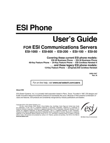
2 ESI-MS dataFigure S3: Relative intensity of the [Ni(C24H24N6)(NO3)] (2), m/z 516.1, (black) and[Cu(C24H24N6)(NO3)] (1), m/z 521.1, (red) species over time showing five oscillationcycles.S5
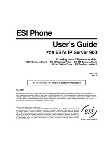
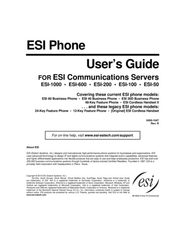
Figure S4: MS spectra showing the change in stoichiometry from [Cu(C24H24N6)(NO3)] (1), m/z 521.1 to [Cu2(C24H24N6)(NO3)2]2 (3),m/z 323.0 when the flow rate of the Cu(NO3)2·6H2O was increased (where a MS of ttop; b 1 ttop:2 Cu(NO3)2·6H2O; c 1 ttop:3Cu(NO3)2·6H2O; d 1 ttop:5 Cu(NO3)2·6H2O; e 1 ttop:15 Cu(NO3)2·6H2O).S6
All solutions were pumped by means of Tricontinent C-3000 syringe pumps equipped with 1 mL syringes for the starting materials, and with a 5 mL syringe for the dilution . where pump A, B and C have 1 mL syringes, and pump D has a 5 mL syringe. The pale blue channels represent the tubing, the T denotes the T-piece where the dilution