Transcription
Anchoring the WorldSince 1912, Chance has been the international leader in earth anchoring. Ourhelical piers are used worldwide to secure residential and commercial buildings,tower foundations, heavy equipment foundations and many other deep foundationapplications.Engineered for dependability and long-term stability, CHANCE helical piersfeature exclusive anchoring techniques, tools, designs and sizes that make otherfoundation methods a thing of the past.Approved by all national building code agencies, CHANCE helical piers are yourfirst line of defense against poor soil conditions, landslides, floods and time.Demand ABetter FoundationWith nearly 400 dealers and distributors nationwide and in Canada, Chance is ready toprovide you everything you need to get the job done right. Chance offers engineeringguidance, field supervision, accessibility, warehouses, material traceability, AWCcertified welders, technical support and complete documentation.Ask a distributor near you for our comprehensive design manual (hardcopy or CD)or download a complete CSI Manu-Spec online. Demand a better foundation today.Locate your nearest distributor at www.abchance.com.Down. Right. Solid.Our tagline is our promise. CHANCE helical piers and anchors go down with power intothe ground and are accurate, level and right the first time. The result is solid stability.ISO 9001:2000A.B. CHANCE, a Division of Hubbell Power Systems, Inc.210 N. Allen, Centralia, MO 65240 USAEmail: hpsliterature@hps.hubbell.comTel: 573/682-8414 Fax: 573/682-8660Because Copyright 2005 Hubbell, Inc. / Printed in USA / A&J40M8/05 / Bulletin 01-0505Certificate No.001136
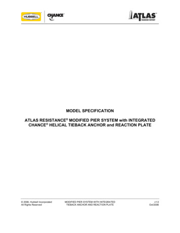
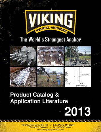
New Foundation Systemsfor Civil Construction Applications:Residential, Commercial and IndustrialFor new deep foundations, CHANCE helical piers are installed at intervalsbetween the footing forms and tie into the rebar gridwork prior to pouringconcrete. The steel piers are extended to depths attaining the installing torquecorrelated to the required load bearing capacity.For sample specs,technical library,case histories anddistributors, go towww.abchance.com Reach competent soil below active zone Predictable via torque-to-capacity ratio No excavation or spoils to remove Loads may be immediately applied Installs in limited access Installs in any weather condition Loads may be immediately applied Installs in limited access Installs in any weather conditionThe Shape of StabilityThe true helix geometry of each steelbearing plate minimizes soil disturbanceduring the vibration-free installation.Approved by BOCA, ICBO, SBCCI, CCMCand ICC, CHANCE helical piers havebecome the deep foundation system ofchoice for architects, builders, contractors, engineers and geotechnical firms.Foundation Repair andAugmentation Systemsfor Residential, Commercial and Industrial Applications:For stabilizing/lifting foundations or retrofitting to increase load capacity, CHANCE steel piers are installed atintervals around the perimeter at affected locations. Independent of the structure, the piers are extended todepths which attain the installing torque correlated to the required load bearing capacity.Special brackets are located where needed around the perimeter and secured to the concrete foundation.Then a steel pier is torqued into the soil through each bracket.The brackets permit lifting by hydraulic jacks. Tightening the nuts onthe bracket vertical bolts locks off the load. Reach competent soil below active zone Predictable via torque-to-capacity ratio No excavation or spoils to remove Loads may be immediately applied Installs in limited access/low headroom Installs in any weather conditionCHANCE Helical Piershave 11 2" to 21 4" solidsquare shafts or 31 2"pipe shafts with helicalplates 8" to 14" indiameter.For more details, seeBulletin No. 01-0502and Technical Manual01-9601.The 278 Pile Systemtransfers loads to theend of its steel shaft(27 8"-diameter pipe,0.203" wall). Specialdesign's 10" drive platepenetrates rugged soiland blunt shaft endbears on solid rock.For more details, seeBulletin No. 01-0501.CHANCE Combo Pilesprovides maximuminstallation ease andload capacity per helixplus enhanced lateralstability of the uppersection where required.They combine helicallead shafts of 11 2"square solid steel with278 Pile plain extensionsvia a transition coupling.For more details, seeBulletin No. 01-0501.The CHANCE HELICALPULLDOWN Micropileconstructs a groutcolumn around theshaft of a helical pierfor sites with weaksurface soil conditions.For more details, seeBulletin No. 01-0201.CHANCE Helical Piershave 11 2" to 21 4" solidsquare shafts or 31 2" pipeshafts with helical plates8" to 14" in diameter.For more details, seeTechnical Manual 01-9601.HeliCAP EngineeringSoftware helps designprofessionals quicklyderive the properhelical pier for siteand load-specific data.For a free demo, visitwww.abchance.com.Then contact your localDistributor or TerritoryManager about how toget a copy for your PC.Cutaway close up of drive endbearing on shallow rock stratumDesign professionals may request a New Construction Design Manual on CDfrom their Distributor or Territory Manager listed on www.abchance.com.*DesignLoad2Steel Pier Types†Certain pier types listed meet a portion of the associated design load range.†0 — 25 kip SS5 Square Shaft Piers & 27 8" Combo Piles26 — 50 kip SS150 & SS175 Square Shaft Piers & Combo Piles51 — 150 kip SS200 & SS225 Square Shaft Piers & Helical Pulldown Micropiles*Based on a Safety Factor of 2 for pier ultimate loads.*DesignLoadSteel Pier Types†Certain pier types listed meet a portion of the associated design load range.†0 — 25 kip SS5 Square Shaft Piers, 278 Pile System & 27 8" Combo Piles26 — 50 kip SS150 & SS175 Square Shaft Piers & Combo Piles51 — 150 kip SS200 & SS225 Square Shaft Piers & Helical Pulldown Micropiles*Based on a Safety Factor of 2 for pier ultimate loads.3
New Foundation Systemsfor Civil Construction Applications:Residential, Commercial and IndustrialFor new deep foundations, CHANCE helical piers are installed at intervalsbetween the footing forms and tie into the rebar gridwork prior to pouringconcrete. The steel piers are extended to depths attaining the installing torquecorrelated to the required load bearing capacity.For sample specs,technical library,case histories anddistributors, go towww.abchance.com Reach competent soil below active zone Predictable via torque-to-capacity ratio No excavation or spoils to remove Loads may be immediately applied Installs in limited access Installs in any weather condition Loads may be immediately applied Installs in limited access Installs in any weather conditionThe Shape of StabilityThe true helix geometry of each steelbearing plate minimizes soil disturbanceduring the vibration-free installation.Approved by BOCA, ICBO, SBCCI, CCMCand ICC, CHANCE helical piers havebecome the deep foundation system ofchoice for architects, builders, contractors, engineers and geotechnical firms.Foundation Repair andAugmentation Systemsfor Residential, Commercial and Industrial Applications:For stabilizing/lifting foundations or retrofitting to increase load capacity, CHANCE steel piers are installed atintervals around the perimeter at affected locations. Independent of the structure, the piers are extended todepths which attain the installing torque correlated to the required load bearing capacity.Special brackets are located where needed around the perimeter and secured to the concrete foundation.Then a steel pier is torqued into the soil through each bracket.The brackets permit lifting by hydraulic jacks. Tightening the nuts onthe bracket vertical bolts locks off the load. Reach competent soil below active zone Predictable via torque-to-capacity ratio No excavation or spoils to remove Loads may be immediately applied Installs in limited access/low headroom Installs in any weather conditionCHANCE Helical Piershave 11 2" to 21 4" solidsquare shafts or 31 2"pipe shafts with helicalplates 8" to 14" indiameter.For more details, seeBulletin No. 01-0502and Technical Manual01-9601.The 278 Pile Systemtransfers loads to theend of its steel shaft(27 8"-diameter pipe,0.203" wall). Specialdesign's 10" drive platepenetrates rugged soiland blunt shaft endbears on solid rock.For more details, seeBulletin No. 01-0501.CHANCE Combo Pilesprovides maximuminstallation ease andload capacity per helixplus enhanced lateralstability of the uppersection where required.They combine helicallead shafts of 11 2"square solid steel with278 Pile plain extensionsvia a transition coupling.For more details, seeBulletin No. 01-0501.The CHANCE HELICALPULLDOWN Micropileconstructs a groutcolumn around theshaft of a helical pierfor sites with weaksurface soil conditions.For more details, seeBulletin No. 01-0201.CHANCE Helical Piershave 11 2" to 21 4" solidsquare shafts or 31 2" pipeshafts with helical plates8" to 14" in diameter.For more details, seeTechnical Manual 01-9601.HeliCAP EngineeringSoftware helps designprofessionals quicklyderive the properhelical pier for siteand load-specific data.For a free demo, visitwww.abchance.com.Then contact your localDistributor or TerritoryManager about how toget a copy for your PC.Cutaway close up of drive endbearing on shallow rock stratumDesign professionals may request a New Construction Design Manual on CDfrom their Distributor or Territory Manager listed on www.abchance.com.*DesignLoad2Steel Pier Types†Certain pier types listed meet a portion of the associated design load range.†0 — 25 kip SS5 Square Shaft Piers & 27 8" Combo Piles26 — 50 kip SS150 & SS175 Square Shaft Piers & Combo Piles51 — 150 kip SS200 & SS225 Square Shaft Piers & Helical Pulldown Micropiles*Based on a Safety Factor of 2 for pier ultimate loads.*DesignLoadSteel Pier Types†Certain pier types listed meet a portion of the associated design load range.†0 — 25 kip SS5 Square Shaft Piers, 278 Pile System & 27 8" Combo Piles26 — 50 kip SS150 & SS175 Square Shaft Piers & Combo Piles51 — 150 kip SS200 & SS225 Square Shaft Piers & Helical Pulldown Micropiles*Based on a Safety Factor of 2 for pier ultimate loads.3
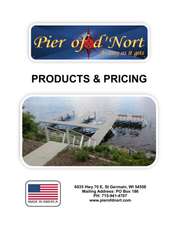
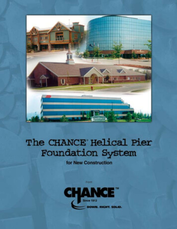
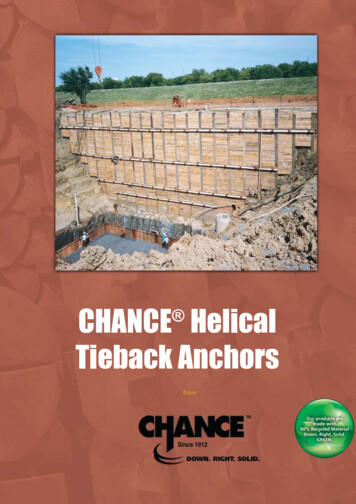
SOIL SCREWRetention Wall SystemHelical Tieback Anchorsfor New Construction and RepairsIn a soil nail application, the SOIL SCREW Retention Wall System constructsa gravity wall to reinforce in-situ soil with screw anchors nearly horizontal.Anchor sizes and grid spacing are determined by soil conditions and loadrequirements. A reinforced shotcrete veneer often is applied to the face.CHANCE tieback anchors for soldier-pile/waler walls come with shaft sizes and single- or multi-helix platediameters selected for job-specific requirements. Building sitework, roadways, retaining walls, levees, damsand revetments are among typical applications. Anchor sizes are determined by soil conditions and loadrequirements. Same installing equipment as soil nails Terminations: Threadbar, stud, crosspin Capacity proportional to install torque No excavation or spoils to remove Installs in any weather conditions Immediate loading No drilling Installs in limited access areas Install with equipment for grouted tendons Terminations for various threadbars Capacity proportional to installing torque No excavation, drilling or spoils to remove Immediate proof testing and loading Permanent or temporary (removable) Installs in any weather Installs in limited access areas No concrete trucks or grout pumps needed Labor saving – as few as four on a crew For sample specs,technical library,case histories anddistributors, go towww.abchance.comTo remove the performance uncertainties and associated costs of grouted soilnails in soils of low shear strength, a SOIL SCREW anchor acts as a bearingdevice. This load-bearing mode is its fundamental superiority compared to agrouted anchor which relies on friction between the soil and the grout.For more details, see Bulletin No. 31-0502.Chance tieback anchors can be tested immediately following installation by conventional rotary drillingequipment. They remove performance uncertainties and associated costs of grouted tendons formed in loosesandy soils and low-shear-strength clays.SOIL SCREW Design Manual,available on www.abchance.com,is based on FHWA design-buildguidelines and key software forinternal and global stability. It alsocompares to tiebacks and MSEwalls.HeliCAP EngineeringSoftware helps designprofessionals quicklyderive the proper helicaltieback anchor for siteand load-specific data.For a free demo, visitwww.abchance.com.Then contact your localDistributor or TerritoryManager about how toget a copy for your PC.For more details, see Bulletin No.31-0501.4For job-specific selections, leading and extension sections come with two orthree 8"-diameter helical bearing plates spaced along the entire length of their11 2" square shafts. All components are available hot-dip galvanized per ASTMA 153 after fabrication. Each SOIL SCREW anchor has a 5,500 ft-lb torque ratingand a 70 kip ultimate tension rating.For job-specific combinations, helical tieback anchors have shafts in four square sizes (11 2", 13 4", 2” and 21 4")with helices in configurations of two to four and diameters from 6" to 14". Their torque ratings range from5,500 to 20,000 ft-lb and ultimate tension ratings from 55 to 200 kip. All components are available hot-dipgalvanized per ASTM A 153 after fabrication.5
SOIL SCREWRetention Wall SystemHelical Tieback Anchorsfor New Construction and RepairsIn a soil nail application, the SOIL SCREW Retention Wall System constructsa gravity wall to reinforce in-situ soil with screw anchors nearly horizontal.Anchor sizes and grid spacing are determined by soil conditions and loadrequirements. A reinforced shotcrete veneer often is applied to the face.CHANCE tieback anchors for soldier-pile/waler walls come with shaft sizes and single- or multi-helix platediameters selected for job-specific requirements. Building sitework, roadways, retaining walls, levees, damsand revetments are among typical applications. Anchor sizes are determined by soil conditions and loadrequirements. Same installing equipment as soil nails Terminations: Threadbar, stud, crosspin Capacity proportional to install torque No excavation or spoils to remove Installs in any weather conditions Immediate loading No drilling Installs in limited access areas Install with equipment for grouted tendons Terminations for various threadbars Capacity proportional to installing torque No excavation, drilling or spoils to remove Immediate proof testing and loading Permanent or temporary (removable) Installs in any weather Installs in limited access areas No concrete trucks or grout pumps needed Labor saving – as few as four on a crew For sample specs,technical library,case histories anddistributors, go towww.abchance.comTo remove the performance uncertainties and associated costs of grouted soilnails in soils of low shear strength, a SOIL SCREW anchor acts as a bearingdevice. This load-bearing mode is its fundamental superiority compared to agrouted anchor which relies on friction between the soil and the grout.For more details, see Bulletin No. 31-0502.Chance tieback anchors can be tested immediately following installation by conventional rotary drillingequipment. They remove performance uncertainties and associated costs of grouted tendons formed in loosesandy soils and low-shear-strength clays.SOIL SCREW Design Manual,available on www.abchance.com,is based on FHWA design-buildguidelines and key software forinternal and global stability. It alsocompares to tiebacks and MSEwalls.HeliCAP EngineeringSoftware helps designprofessionals quicklyderive the proper helicaltieback anchor for siteand load-specific data.For a free demo, visitwww.abchance.com.Then contact your localDistributor or TerritoryManager about how toget a copy for your PC.For more details, see Bulletin No.31-0501.4For job-specific selections, leading and extension sections come with two orthree 8"-diameter helical bearing plates spaced along the entire length of their11 2" square shafts. All components are available hot-dip galvanized per ASTMA 153 after fabrication. Each SOIL SCREW anchor has a 5,500 ft-lb torque ratingand a 70 kip ultimate tension rating.For job-specific combinations, helical tieback anchors have shafts in four square sizes (11 2", 13 4", 2” and 21 4")with helices in configurations of two to four and diameters from 6" to 14". Their torque ratings range from5,500 to 20,000 ft-lb and ultimate tension ratings from 55 to 200 kip. All components are available hot-dipgalvanized per ASTM A 153 after fabrication.5
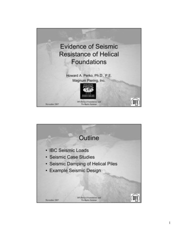
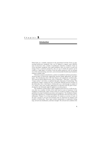
Outdoor LightingHelical FoundationsTelecom and PowerTower Foundations and Guy Anchorsfor Decorative & Architectural LightingPCS telecom and electric utility transmission towers have beenconstructed and augmented for upgrades in record time on terrainnearly inaccessible using CHANCE INSTANT FOUNDATION and guyanchors.In 10 minutes a crew of two can complete this clean installation, ready for thelighting standard to be set. A steel CHANCE INSTANT FOUNDATION pier simply torques to grade by conventional hydraulic rotary equipment. Power conduit feeds into the side cableway, up and out the top. The variable bolt-circlebaseplate bolts directly to the lighting standard without alignment problems.Sizes combine 31 2", 4", or 65 8" pipe shafts 56" or 64" long with a 10" or 12"helix, plus sizes for Bollard lighting. For more details, see Bulletin No. 02-0301.For sample specs,technical library,case histories anddistributors, go towww.abchance.comTypical applications are anchor grillages for guyed and self-supportedtowers and equipment platform foundations. Connections may be bysteel brackets or rebar gridwork of a concrete cap. For site-specificdesigns, these helical piers come in types matched to resist associatedbending moments and lateral loads: Type HS (High Strength) – 31 2" pipe 3' to 10' long; lead sections withsingle to triple helical plates 8" to 14"; and extension sections withforged couplers. Type T/C (Tension/Compression) – 31 2" pipe lead sections 5' to 10' longwith single to triple helical plates 8" to 14"; 8" pipe extension sections3' to 10' long with 14" helical couplers. HS/SS Combo Piles – SS 13 4" or 2" square-shaft multi-helix leadsections; 31 2" pipe extension sections with forged couplers. Helical Pulldown Micropiles – 4" to 10" grout column around thecentral shaft above the helical plates of Type SS, Type HS, or HS/SSCombo Piles.Cap Plate connects equipment platform to TypeFor guying towers, Type SS anchors offer up to 200 kip ultimate andmay be applied individually, in pairs, with fan plates or in concrete-cap HS or HS/SS Combo Pile foundationsapplications.For equipment platform supports, Type HS or HS/SS ComboPiles may be quickly installed and connected by a special cap plate assembly.For more details, see Bulletin 01-9701, Bulletin 02-0101 and Bulletin 02-8701.Geo-Environmental Tiedownand Support Systemsfor DOT and Utility LightingApproved for use by many state DOTs and in compliance with ASHTO Section13.9 of the Standard Specification for Structural Supports for Highway Signs,Luminaires and Traffic Signals, CHANCE INSTANT FOUNDATION anchors typically install in minutes for immediate mounting of the superstructure.By design, these steel foundations overcome the stresses of tension, compression and shear. Highly resistant to overturning moments, they are selectedbased on site and application requirements.Sizes combine 65 8", 85 8" or 103 4" pipeshafts 5' or 7' long with a 12", 14" or 16"helix. For more details, see Bulletin No. 02-8701.for Parking and Area Lighting6For light standards with bumper protection, penetration of a steel CHANCE INSTANT FOUNDATION anchor is stopped at the desired height. Power conduitis fed into the side cableway, up and out the baseplate. Then a form for theabove-grade bumper is placed around the exposed Instant Foundation shaft toencase all but the baseplate in a poured-concrete cylinder.Sizes combine 65 8" or 85 8" pipe shafts 5', 8' or 10' long with a 12" or 14" helix.For more details, see Bulletin No. 02-9705.For these applications, helical piers and anchors are shown on the preceding pages.Harbor/aquaculture moorings –Anchors install from surface. Shorter scoping chains fit more boats per harbor and reducescouring of ecosystems on bottom. Retrievable anchors keep fish pens and ice barriersdependably positioned.For more details, see Bulletin 31-9301, Bulletin 31-9303, Bulletin 31-9305, Bulletin 319306, Bulletin 31-9604, Bulletin 31-9605, and Bulletin 31-9606.Walkway supports –Anchor systems and portable installing equipment access sensitive wetlands with minimal disturbance. Loads transfer to bearing stratum to isolate structure from seasonalchanges.For more details, see Bulletin 04-9409, Bulletin 04-9605 and Bulletin 31-9503.Pipeline and storage tanks –Special hardware combines with anchors to overcome buoyancy and provide support,considering specific tension and compression loads.For more details, see Bulletin 30-8101 and Bulletin 30-8201.7
Outdoor LightingHelical FoundationsTelecom and PowerTower Foundations and Guy Anchorsfor Decorative & Architectural LightingPCS telecom and electric utility transmission towers have beenconstructed and augmented for upgrades in record time on terrainnearly inaccessible using CHANCE INSTANT FOUNDATION and guyanchors.In 10 minutes a crew of two can complete this clean installation, ready for thelighting standard to be set. A steel CHANCE INSTANT FOUNDATION pier simply torques to grade by conventional hydraulic rotary equipment. Power conduit feeds into the side cableway, up and out the top. The variable bolt-circlebaseplate bolts directly to the lighting standard without alignment problems.Sizes combine 31 2", 4", or 65 8" pipe shafts 56" or 64" long with a 10" or 12"helix, plus sizes for Bollard lighting. For more details, see Bulletin No. 02-0301.For sample specs,technical library,case histories anddistributors, go towww.abchance.comTypical applications are anchor grillages for guyed and self-supportedtowers and equipment platform foundations. Connections may be bysteel brackets or rebar gridwork of a concrete cap. For site-specificdesigns, these helical piers come in types matched to resist associatedbending moments and lateral loads: Type HS (High Strength) – 31 2" pipe 3' to 10' long; lead sections withsingle to triple helical plates 8" to 14"; and extension sections withforged couplers. Type T/C (Tension/Compression) – 31 2" pipe lead sections 5' to 10' longwith single to triple helical plates 8" to 14"; 8" pipe extension sections3' to 10' long with 14" helical couplers. HS/SS Combo Piles – SS 13 4" or 2" square-shaft multi-helix leadsections; 31 2" pipe extension sections with forged couplers. Helical Pulldown Micropiles – 4" to 10" grout column around thecentral shaft above the helical plates of Type SS, Type HS, or HS/SSCombo Piles.Cap Plate connects equipment platform to TypeFor guying towers, Type SS anchors offer up to 200 kip ultimate andmay be applied individually, in pairs, with fan plates or in concrete-cap HS or HS/SS Combo Pile foundationsapplications.For equipment platform supports, Type HS or HS/SS ComboPiles may be quickly installed and connected by a special cap plate assembly.For more details, see Bulletin 01-9701, Bulletin 02-0101 and Bulletin 02-8701.Geo-Environmental Tiedownand Support Systemsfor DOT and Utility LightingApproved for use by many state DOTs and in compliance with ASHTO Section13.9 of the Standard Specification for Structural Supports for Highway Signs,Luminaires and Traffic Signals, CHANCE INSTANT FOUNDATION anchors typically install in minutes for immediate mounting of the superstructure.By design, these steel foundations overcome the stresses of tension, compression and shear. Highly resistant to overturning moments, they are selectedbased on site and application requirements.Sizes combine 65 8", 85 8" or 103 4" pipeshafts 5' or 7' long with a 12", 14" or 16"helix. For more details, see Bulletin No. 02-8701.for Parking and Area Lighting6For light standards with bumper protection, penetration of a steel CHANCE INSTANT FOUNDATION anchor is stopped at the desired height. Power conduitis fed into the side cableway, up and out the baseplate. Then a form for theabove-grade bumper is placed around the exposed Instant Foundation shaft toencase all but the baseplate in a poured-concrete cylinder.Sizes combine 65 8" or 85 8" pipe shafts 5', 8' or 10' long with a 12" or 14" helix.For more details, see Bulletin No. 02-9705.For these applications, helical piers and anchors are shown on the preceding pages.Harbor/aquaculture moorings –Anchors install from surface. Shorter scoping chains fit more boats per harbor and reducescouring of ecosystems on bottom. Retrievable anchors keep fish pens and ice barriersdependably positioned.For more details, see Bulletin 31-9301, Bulletin 31-9303, Bulletin 31-9305, Bulletin 319306, Bulletin 31-9604, Bulletin 31-9605, and Bulletin 31-9606.Walkway supports –Anchor systems and portable installing equipment access sensitive wetlands with minimal disturbance. Loads transfer to bearing stratum to isolate structure from seasonalchanges.For more details, see Bulletin 04-9409, Bulletin 04-9605 and Bulletin 31-9503.Pipeline and storage tanks –Special hardware combines with anchors to overcome buoyancy and provide support,considering specific tension and compression loads.For more details, see Bulletin 30-8101 and Bulletin 30-8201.7
Anchoring the WorldSince 1912, Chance has been the international leader in earth anchoring. Ourhelical piers are used worldwide to secure residential and commercial buildings,tower foundations, heavy equipment foundations and many other deep foundationapplications.Engineered for dependability and long-term stability, CHANCE helical piersfeature exclusive anchoring techniques, tools, designs and sizes that make otherfoundation methods a thing of the past.Approved by all national building code agencies, CHANCE helical piers are yourfirst line of defense against poor soil conditions, landslides, floods and time.Demand ABetter FoundationWith nearly 400 dealers and distributors nationwide and in Canada, Chance is ready toprovide you everything you need to get the job done right. Chance offers engineeringguidance, field supervision, accessibility, warehouses, material traceability, AWCcertified welders, technical support and complete documentation.Ask a distributor near you for our comprehensive design manual (hardcopy or CD)or download a complete CSI Manu-Spec online. Demand a better foundation today.Locate your nearest distributor at www.abchance.com.Down. Right. Solid.Our tagline is our promise. CHANCE helical piers and anchors go down with power intothe ground and are accurate, level and right the first time. The result is solid stability.ISO 9001:2000A.B. CHANCE, a Division of Hubbell Power Systems, Inc.210 N. Allen, Centralia, MO 65240 USAEmail: hpsliterature@hps.hubbell.comTel: 573/682-8414 Fax: 573/682-8660Because Copyright 2005 Hubbell, Inc. / Printed in USA / A&J40M8/05 / Bulletin 01-0505Certificate No.001136
CHANCE Helical Piers have 11 2" to 21 4" solid square shafts or 31 2" pipe shafts with helical plates 8" to 14" in diameter. For more details, see Bulletin No. 01-0502 and Technical Manual 01-9601. The CHANCE HELICAL PULLDOWN Micropile constructs a grout column around the shaft of a helical pier for sites with weak