Transcription
TEMPERATURE MANAGEMENT SYSTEMMODEL 5000 SERVICE MANUAL Simply Advanced
SERVICETEMPERATURE MANAGEMENT SYSTEMMANUALTABLE OF CONTENTSChapter 1 – Getting Started .1Introduction .1Indications for Use .1Warnings and Cautions .1System Setup .2System Navigation.3Therapy Screens .3Fill Reservoir .3Manual Control .4Functional Verification .4Chapter 2 Components .4Hydraulic Components .4Electronic Components .5Chapter 3 Theory of Operation .6Main Hydraulic Circuits .6Ancillary Hydraulic Circuits .6Electronic Control System .6Chapter 4 – Maintenance .6Maintenance Schedule .6Clean the External Surfaces .6Inspect Connectors and Cables .6Clean the Condenser .6Replenish Cleaning Solution .7Inspect Screen Protector .7Inspect Fluid Delivery Line .7Preventative Maintenance .7Calibration .7Chapter 5 – Advanced Setup .7Chapter 6 – Alarms and Alerts .8Alarms .8Main Safety Alarms .8Non-Recoverable Alarms .8Recoverable Alarms .8Alerts .8Alarms and Alert Listing .9Chapter 7 – Troubleshooting .147.1 Diagnostic Screen .147.2 Event Log .147.3 General Troubleshooting Guide.147.4 Troubleshooting Assistance .15Chapter 8 – Component Replacement.168.1 Tools Required.218.2 Drain the Control Module.218.3 Remove Back Panel .218.4 Remove Outer Shell .228.5 Removing / Replacing Circuit Cards from Card Cage .238.6 Replacing Upper Components .248.7 Removing Internal Components from Chiller Frame .258.8 Separating the Internal Components intoTwo Sections .268.9 Replacing Mixing Pump .278.10 Replacing Circulation Pump .288.11 Replacing Drain Valves .298.12 Replacing AC Chiller Pump .308.13 Replacing DC Chiller Pump .318.14 Replacing Heater .328.15 Replacing Flowmeter .338.16 Replacing Control Panel .338.17 Replacing Chiller .348.18 Replacing Tank Temperature Sensor Harness .348.19 Replacing Manifold Harness.358.20 Replacing Inlet/Outlet Manifold .368.21 Replacing Level Sensor.368.22 Replacing Power Module .368.23 Replacing Mains Voltage Circuit Card .378.24 Replacing the AC Breaker Harness .378.25 Installing Transmission Interface Module .38Chapter 9 – Calibration / Calibration Check .399.1 Calibration Test Unit .399.2 When to Perform a Calibration or Calibration Check.399.3 Calibration Setup .399.4 Performing a Calibration .39Appendix A - Product Specifications.40Arctic Sun Temperature Management SystemSpecifications .41Appendix B - Symbols .42Appendix C - Electromagnetic Compatibility.43Appendix D - Spare Parts and Accessories .45Appendix E - Temperature Cables .46Appendix F - Installing Software on Control Panel .47Appendix G - Shipping .48Appendix H - Warranty .49Appendix I - Transmission Interface ModuleData Output Format .50
ENGLISHChapter 1 – Getting Started Introduction Sun TemperatureThe ArcticManagement System is a device thatmonitors and controls patient temperature within a range of 32 Cto 38.5 C (89.6 F to 101.3 F). The system consists of the ArcticSun Temperature Management System and disposable ArcticGel Pads. The Arctic Sun Temperature Management System deliverstemperature-controlled water ranging between 4 C and 42 C(39.2 F and 107.6 F) through the pads adhered to the patient’sskin. This results in highly efficient conductive heat transferbetween the water and the patient.The Arctic Sun Temperature Management System was designedwith ease of service in mind and incorporates several features thatwill assist clinical engineers in maintaining its performance. Thesefeatures include: negative pressure flow that eliminates water leaks,real-time air leak detection, and performance monitoring. It alsoincludes access to alarm logs and past system case data, real-timediagnostic information, simplified calibration and maintenance, andmodular construction allowing for simple repair if required. Indications for UseThe Arctic Sun Temperature Management System is a thermalregulating system indicated for monitoring and controlling patienttemperature in adult and pediatric patients of all ages. Warnings and CautionsWarnings Do not use the Arctic Sun Temperature Management System inthe presence of flammable agents because an explosion and/orfire may result. Do not use high frequency surgical instruments or endocardialcatheters while the Arctic Sun Temperature ManagementSystem is in use. There is a risk of electrical shock and hazardous moving parts.There are no user serviceable parts inside. Do not removecovers. Refer servicing to qualified personnel. Power cord has a hospital grade plug. Grounding reliability canonly be achieved when connected to an equivalent receptaclemarked “hospital use” or “hospital grade”. When using the Arctic Sun Temperature Management System,note that all other thermal conductive systems, such as waterblankets and water gels, in use while warming or cooling with theArctic Sun Temperature Management System may actually alteror interfere with patient temperature control. Do not place ArcticGel Pads over transdermal medicationpatches as warming can increase drug delivery, resulting inpossible harm to the patient. WARNING: Parts sold for use with the Arctic Sun Temperature Management System device can expose you tochemicals including di(2-ethylhexyl) phthalate (DEHP), antimonytrioxide, lead, and di-isodecyl phthalate (DIDP), which are knownto the State of California to cause negative impacts to health,such as cancer and birth defects or other reproductive harm. Formore information, go to: https://www.P65Warnings.ca.gov. The Arctic Sun Temperature Management System is notintended for use in the operating room environment.Cautions This product is to be used by or under the supervision of trained,qualified medical personnel. Federal law (USA) restricts this device to sale, by or on the order ofa physician. Use only sterile water. The use of other fluids will damage the ArcticSun Temperature Management System. When moving the Arctic Sun Temperature Management Systemalways use the handle to lift the controller over an obstacle to avoidover balancing.The patient’s bed surface should be located between 30 and 60inches (75 cm and 150 cm) above the floor to ensure proper flowand minimize risk of leaks.The clinician is responsible to determine the appropriateness ofcustom parameters. When the system is powered off, all changesto parameters will revert to the default unless the new settings havebeen saved as new defaults in the Advanced Setup screen. For smallpatients ( 30 kg) it is recommended to use the following settings:Water Temperature High Limit 40 C (104 F); Water TemperatureLow Limit 10 C (50 F); Control Strategy 2.The operator must continuously monitor patient temperature whenusing Manual Control and adjust the temperature of the waterflowing through the pads accordingly. Patient temperature will notbe controlled by the Arctic Sun Temperature Management Systemin Manual Control.Due to the system’s high efficiency, Manual Control is notrecommended for long duration use. The operator is advised touse the automatic therapy modes (e.g. Control Patient, CoolPatient, Rewarm Patient) for automatic patient temperaturemonitoring and control.The Arctic Sun Temperature Management System will monitor andcontrol patient core temperature based on the temperature probeattached to the system. The clinician is responsible for correctlyplacing the temperature probe and verifying the accuracy andplacement of the patient probe at the start of the procedure.Medivance supplies temperature simulators (fixed value resistors)for testing, training and demonstration purposes. Never usethis device, or other method, to circumvent the normal patienttemperature feedback control when the system is connected to thepatient. Doing so exposes the patient to the hazards associated withsevere hypo- or hyper-thermia.Medivance recommends measuring patient temperature from asecond site to verify patient temperature. Medivance recommendsthe use of a second patient temperature probe connected to theArctic Sun Temperature Management System Temperature 2 inputas it provides continuous monitoring and safety alarm features.Alternatively, patient temperature may be verified periodically withindependent instrumentation.The displayed temperature graph is for general informationpurposes only and is not intended to replace standard medicalrecord documentation for use in therapy decisions.Patient temperature will not be controlled and alarms are notenabled in Stop Mode. Patient temperature may increase ordecrease with the Arctic Sun Temperature Management Systemin Stop Mode.Carefully observe the system for air leaks before and duringuse. If the pads fail to prime or a significant continuous air leakis observed in the pad return line, check connections. If needed,replace the leaking pad. Leakage may result in lower flow ratesand potentially decrease the performance of the system.The Arctic Sun Temperature Management System is for useonly with the ArcticGel Pads.The ArcticGel Pads are only for use with the Arctic Sun Temperature Management Systems.The ArcticGel Pads are non-sterile for single patient use. Donot reprocess or sterilize. If used in a sterile environment, padsshould be placed according to the physician’s request, eitherprior to the sterile preparation or sterile draping. ArcticGel Padsshould not be placed on a sterile field.Use pads immediately after opening. Do not store pads once thekit has been opened.Do not place ArcticGel Pads on skin that has signs ofulceration, burns, hives, or rash.While there are no known allergies to hydrogel materials, cautionshould be exercised with any patient who has a history of skinallergies or sensitivities.1
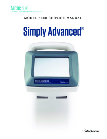
SERVICE 2MANUALSystem are other than those specified by Medivance.Do not allow circulating water to contaminate the sterile fieldAnyone performing the procedures must be appropriatelywhen patient lines are disconnected.trained and qualified.The water content of the hydrogel affects the pad’s adhesionto the skin and conductivity, and therefore, the efficiency ofSystem Setupcontrolling patient temperature. Periodically check that padsremain moist and adherent. Replace pads when the hydrogelUnpackno longer uniformly adheres to the skin. Replacing pads at least1) Unpack the Arctic Sun Temperature Management Systemevery 5 days is recommended.Control Module and accessories.Do not puncture the ArcticGel Pads with sharp objects.2) Allow the control module to remain upright for at least 2 hoursPunctures will result in air entering the fluid pathway and mayprior to completing the installation and setup procedure in orderreduce performance.to allow the chiller oil to settle. Damage to the chiller compressor If accessible, examine the patient’s skin under the ArcticGelmay result otherwise.Pads often, especially those at higher risk of skin injury. Skininjury may occur as a cumulative result of pressure, time andConnectionstemperature. Possible skin injuries include bruising, tearing, skin1) Use only Medivance approved cables and accessories with theulcerations, blistering, and necrosis. Do not place bean bag orArctic Sun Temperature Management System Controlother firm positioning devices under the ArcticGel Pads. Do notModule. Connect the Fluid Delivery Line, Patient Temp 1 cable,place positioning devices under the pad manifolds orPatient Temp 2 cable (optional) and Fill Tube to the back of thepatient lines.control module.The rate of temperature change and potentially the final2) Plug the Power Cord into the wall outlet. Position Arctic Sun achievable patient temperature is affected by many factors.Temperature Management System so that access to the powerTreatment application, monitoring and results are thecord is not restricted.responsibility of the attending physician. If the patient does notreach target temperature in a reasonable time or the patient isnot able to be maintained at the target temperature, the skin maybe exposed to low or high water temperatures for an extendedperiod of time which may increase the risk for skin injury. Ensurethat pad sizing/coverage and custom parameter settings arecorrect for the patient and treatment goals, water flow is greaterthan or equal to 2.3 liters per minute and the patient temperatureprobe is in the correct place. For patient cooling, ensureenvironmental factors such as excessively hot rooms, heat lamps,and heated nebulizers are eliminated and patient shiveringPower SwitchPatientis controlled. Otherwise, consider increasing minimum waterTemp 1temperature, modifying target temperature to an attainablePatientsetting or discontinuing treatment. For patient warming, consider Strain ReliefTempOutdecreasing maximum water temperature, modifying targettemperature to an attainable setting or discontinuing treatment.PatientTemp 2Due to underlying medical or physiological conditions, somepatients are more susceptible to skin damage from pressurePatientand heat or cold. Patients at risk include those with poor tissueTemp Cableperfusion or poor skin integrity due to diabetes, peripheralvascular disease, poor nutritional status, steroid use or highFluiddose vasopressor therapy. If warranted, use pressure relievingDeliveryFill Tubeor pressure reducing devices under the patient to protect fromLineParkingskin injury.Do not allow urine, antibacterial solutions or other agents to poolunderneath the ArcticGel Pads. Urine and antibacterial agents Fill Tube/Portcan absorb into the pad hydrogel and cause chemical injury andloss of pad adhesion. Replace pads immediately if these fluidscome into contact with the hydrogel.Do not place ArcticGel Pads over an electrosurgical groundingpad. The combination of heat sources may result in skin burns.Power CordIf needed, place defibrillation pads between the ArcticGel PadsEquipotentialDrain Valvesand the patient’s skin.Stud Carefully remove ArcticGel Pads from the patient’s skin at the AirFiltercompletion of use. Discard used ArcticGel Pads in accordancewith hospital procedures for medical waste.The USB data port is to be used only with a standalone USB flashdrive. Do not connect to another mains powered device duringpatient treatment.Fig. 1-1 Arctic Sun Temperature Management SystemUsers should not use cleaning or decontamination methodsControl Moduledifferent from those recommended by the manufacturer without firstchecking with the manufacturer that the proposed methods will notdamage the equipment. Do not use bleach (sodium hypochlorite)as it may damage the system.Medivance will not be responsible for patient safety or equipmentperformance if the procedures to operate, maintain, modify orservice the Medivance Arctic Sun Temperature Management
ENGLISHCSystem NavigationGLDPFHJEIMNKAOBQRFig. 1-5 Hypothermia Therapy screenFig. 1-2 Start-up screen with training moduleThe following information is displayed and functions are availablefrom the Normothermia and Hypothermia therapy screens.A training module including a section for Clinical Engineering(Setup and Maintenance) is available from the start-up screen.Fig. 1-3 Therapy Selection screenWhen the self-test is complete, the Patient Therapy Selectionscreen will appear on the control panel.Therapy ScreensCGLDPFEHJIMNKOA Cool Patient window (Hypothermia screen)Control Patient window (Normothermia screen)B Rewarm Patient window (Hypothermia screen)C Patient Monitoring areaD Patient TemperatureE Patient Temperature 2 (if enabled)F Patient Temperature Trend IndicatorG System Monitoring areaH Water TemperatureI Water Flow RateJ Reservoir Water LevelK Therapy GraphL Manual Control button (if enabled)M Empty Pads buttonN Fill Reservoir buttonO Therapy Selection / Screen Lock buttonP Temperature Units button (if enabled)Q Stop buttonR Help buttonFill Reservoir1) Fill the reservoir with sterile water only.2) Four liters of water will be required to fill the reservoir atinitial installation.3) Add one vial of Arctic Sun Temperature Management SystemCleaning Solution to the sterile water.4) From the Patient Therapy Selection screen, press either theNormothermia or Hypothermia button, under the New Patientheading.5) From the Hypothermia or Normothermia therapy screen,press the Fill Reservoir button.6) The Fill Reservoir screen will appear. Follow the directions onthe screen.AQRFig. 1-4 Normothermia Therapy screenFig. 1-6 Fill Reservoir screen3
SERVICEMANUALManual ControlManual Control allows the user to directly set the water temperaturein the Circulating Tank. It does not require a patient temperatureprobe to be connected and therefore can be used for troubleshootingand diagnostic purposes.If Manual Control has been disabled it will need to be enabled. Toenable Manual Control, from the Normothermia Therapy screenpress the Adjust button located at the bottom center of the screen.From the Control Patient-Adjust screen, press the More button.This will display the Normothermia Settings screen (Fig. 1-9).Press the adjust button for manual control. Select the desired watertemperature and time. Press Save. Enabling Manual Control will notautomatically change the default settings.When enabled, the Manual Control button is visible in the upper righthand corner of the Therapy screen. Pressing the Manual Controlbutton allows the user to change the water target and duration, andto start Manual Control.Control PatientFig 1-7 Control Patient panel from Normothermia screenFig. 1-10 Manual Control panel (appears after user presses ManualControl on main Normothermia or Hypothermia Screen)Functional VerificationCertificates of Conformance for calibration, performance, andelectrical safety tests are included with the shipment of eachArctic Sun Temperature Management System. To verify thesystem will heat and cool properly, perform the following:1) Power On the control module2) From the Patient Therapy Selection screen, press theHypothermia button to display the Hypothermia therapyscreen.3) From the Hypothermia therapy screen, press the ManualControl button to open the Manual Control window.4) Use the Up and Down arrows to set the Manual Control watertarget temperature to 40 C and the duration to 30 minutes.5) Press the Start button to initiate Manual Control. Allow at least3 minutes for the system to stabilize.6) Monitor the flow rate and water temperature in the Systemstatus area on the Hypothermia therapy screen.7) Verify that the flow rate reaches at least 1.5 liters/minute.8) Verify that the water temperature increases to 30 C.9) Press the Stop button.10) Set the Manual Control water target temperature to 4 C and theduration to 30 minutes.11) Press the Start button to initiate Manual Control.12) Monitor the flow rate and water temperature in the Systemstatus area of the Hypothermia therapy screen. Verify that thewater temperature drops to 6 C.13) Press the Stop button to stop Manual Control14) Press the Cancel button to close the Manual Control window15) Power Off the control module.Chapter 2 ComponentsFig 1-8 Control Patient - Adjust panel(appears after user presses Adjust on Control Patient panel)Fig 1-9 Normothermia Settings screen4Hydraulic ComponentsFluid Delivery Line – reusable dual lumen tubing that connects theControl Module to the ArcticGel Pads.PumpsCirculation Pump – pumps water from the Circulation Tankthrough the ArcticGel Pads.Mixing Pump – Transfers cold water from the Chiller Tank tothe Circulation Tank.Chiller Pump – continuously circulates the water from theChiller Tank through the chiller’s evaporator.TanksCirculation Tank – contains temperature-controlled water thatsupplies the ArcticGel Pads.Chiller Tank – contains water that is maintained atapproximately 4 C.Supply Tank – contains water that is used to replenish theCirculation Tank when the ArcticGel Pads are filled.
ENGLISHSensorsOutlet Monitor Temperature - T1 – located within theCirculation Tank. Used to monitor the temperature of water thatsupplies the ArcticGel Pads.Outlet Control Temperature - T2 – located within theCirculation Tank. Used to control the temperature of water thatsupplies the ArcticGel Pads.Inlet Temperature – T3 – located within the Inlet/OutletManifold. Monitors the temperature of water returning from theArcticGel Pads.Chiller Temperature – T4 – located within the Chiller Tank.Used to control temperature of water in the Chiller Tank.Pressure Sensor – located within the Inlet/Outlet Manifold.Used to maintain a constant negative pressure withinthe ArcticGel Pads by controlling the speed of theCirculation Pump.Flow Sensor – located at the outlet of the Circulation Pump.Monitors the flow rate in the Circulation Circuit.ValvesConditioning Valve – located within the Inlet/Outlet Manifold.When open, allows water to circulate internally when priming orpreconditioning.Fill Valve – located within the Inlet/Outlet Manifold. When open,allows the Circulation Pump to draw water into the system.Vent Valve – located within the Inlet/Outlet Manifold. Whenopen, allows air to supply ArcticGel Pads and the displacedwater to be returned to the Supply Tank.Heater – located in the Circulation Tank. The heater consists of4 heating rods. The heating element within each rod is in serieswith a non-resettable thermal fuse, which protects each rodagainst an over-temperature condition.Inlet/Outlet Manifold – connects to Fluid Delivery Line and FillTube. Contains the valves, the inlet temperature sensor, and thepressure sensor.Chiller – a refrigeration unit that continuously coolsthe evaporator.Electronic ComponentsCables – power cord and temperature cables. Additionaladapter cables are available to purchase for use with differentmanufacturers’ temperature probes. In addition, temperature outcables can be purchased to allow output of patient temperatureto an external monitor. Please refer to the Temperature Cablesin Appendix E.The Mains Voltage Circuit Card – located below the SupplyTank. Includes electromechanical relays to control mains powerto the chiller and heater. Also includes solid state relays tocontrol power to each of the four heating elements.Power Module – located next to the Mains Voltage Circuit Card.Converts AC mains voltage to 24 VDC.Power Circuit Card – located within the Card Cage. Converts24 VDC to lower DC voltages used by the system.The Processor Circuit Card – located within the Card Cage.Includes both the control and monitor microprocessors andassociated circuitry, including nonvolatile memory.The Isolation Circuit Card – located within the Card Cage.Provides electrical isolation for the Patient Temperaturecircuits to a level of 1500V. Also provides a simulated YSI 400compatible patient temperature signal (Temperature Out) to anexternal monitor.The Input/Output Circuit Card – located within the Card Cage.Contains circuits that monitor water temperature, pressure andflow. Provides control for Circulation and Mixing Pumps, valves,and Chiller.The Backplane Circuit Card – located at the back of the CardCage. Interconnects the circuit cards within the card cage.Control Panel – located at the top of the Control Module.Consists of touch screen, microprocessor, hard drive, USBinterface, and USB-powered speaker.ATMOSPHEREVENTCHILLERTANKT4CIRCULATION TANKT1 HEATER T2SUPPLY TANKINLET/OUTLETMANIFOLDVVBVBYPASS LINEFVFILL LINET3P1FLOW CIRCULATIONPUMPCHILLERCIRCUITCIRCULATING CIRCUITVALVEVALVEDRAIN VALVESKEYEVAPORATORAIR FLOWCHILLERARCTICGEL PADAIR FLOWVVBVFVP1T1T2T3T4Vent ValveBypass ValveFill ValvePressure SensorOutlet Monitor TemperatureOutlet Control TemperatureInlet TemperatureChiller TemperatureFig. 2-1 The Hydraulic Schematic5
SERVICEChapter 3 Theory of Operation MANUALValve control (VV, BV and FV)Chiller controlMain Hydraulic CircuitsCirculation Circuit – circulates temperature-controlled waterfrom the Circulation Tank through the ArcticGel Pads andreturns to the inlet port of the Circulation Pump. The speed ofthe Circulation Pump varies to maintain -7.0 PSI (0.5 bar) atthe Pressure Sensor. Since water in the ArcticGel Pads flowsunder negative pressure, a break in the circuit, such as a padbeing punctured or disconnected, will result in air leaking into thesystem instead of water leaking out. Air in the system is removedin the Circulation Tank and exits through the tank vent. Whenwarmer water is required, the heaters located in the CirculationTank are energized. The heater power is dependent upon theflow rate through the circulation tank and the difference betweenthe water temperature and the commanded water temperature.The heater has four elements that are cycled on sequentially tominimize power fluctuations in the mains supply.Chiller Circuit – maintains the water in the Chiller Tank atapproximately 4 C. Water is gravity-fed into the centrifugalChiller Pump and is then pumped through the chiller’s evaporatorand returned to the Chiller Tank. The refrigerant system’s coolingcapacity is controlled by a refrigerant valve. When the ChillerCircuit approaches 4 C, the cycling of the valve can be heard.Mixing Circuit – when cold water is required to cool theCirculation Circuit, the Mixing Pump pulls water from theCirculation Tank and meters it into the Chiller Tank. Cold wateroverflows from the Chiller Tank into the Circulation Tank. Thespeed of the mixing pump is dependent upon the flow ratethrough the circulation tank and the difference between the watertemperature and the commanded water temperature.Ancillary Hydraulic CircuitsFilling – When filling, the Fill Valve is opened and water is drawnup through the valve by the Circulation Pump. Water returnsthrough the Circulation Tank to the Supply Tank. NegativePressure must be generated at the inlet of the Inlet/OutletManifold for filling to occur, therefore the Fluid Delivery Line mustbe attached. ArcticGel Pads should not be attached
using Manual Control and adjust the temperature of the water flowing through the pads accordingly. Patient temperature will not be controlled by the Arctic Sun Temperature Management System in Manual Control. Due to the system's high efficiency, Manual Control is not recommended for long duration use. The operator is advised to