Transcription
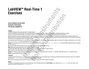
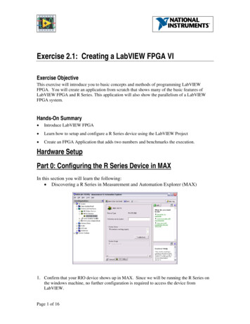
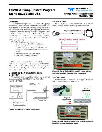
LabVIEW Pump Control ProgramUsing RS232 and USBOverviewThe current Teledyne ISCO D-Series USB pumpcontrollers (identification number 62-1240-114 andhigher) can be controlled remotely using an RS232or USB serial port. The new Teledyne ISCO suppliedLabVIEW Remote Pump Control program willinstall a runtime version of National InstrumentLabVIEW and software to remotely control,communicate, and store data from the TeledyneISCO syringe pumps.The following items are required:Syringe Pump Technical BulletinOct 2020, TB39For RS232 CableTo us the RS232 cable connection a 9 to 25 pinSerial Modem cable is needed (p/n 480-7996-00).Plugs into RS232/485 Port Executable Installer (discussed in thistechnical bulletin) LV2014 Source (See Technical Bulletin 06) Computer running Microsoft Windows 7 orabove RS232 cable (p/n 480-7996-00) or USB cable (p/n 68-1247-504)Please note new controllers, detailed above, comewith an accessory cable kit included, 60-1247-168.This contains 2 cables, one for connecting thecontroller to a USB port and the second option toconnect it to Ethernet.Connecting the Computer to PumpControllerTo connect one controller, either use a serialmodem cable (p/n 480-7996-00) or USB cable(p/n 68-1247-504).See instructionsfor cable selectionFigure 2: Serial Cable 480-7996-00, cable wiring,and plug location on controller rear panelFor USB CableThe USB cable is a special USB Type A to 25 pinsub-D connector (p/n 68-1247-504).Plugs intoUSB/EthernetPortFigure 1: Drawing of cable connectionFigure 3: USB cable 68-1247-504, wiring, and pluglocation on controller rear panel
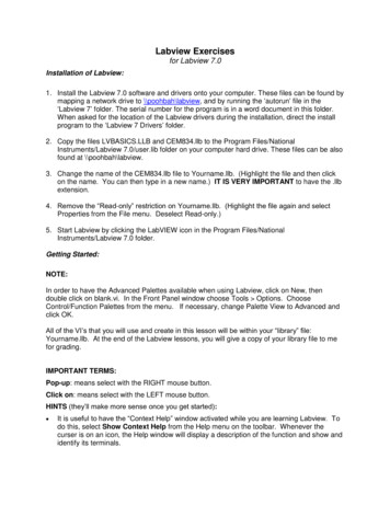
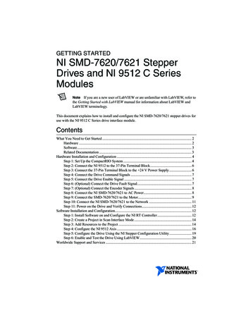
Syringe Pump Technical Bulletin Oct 2020, TB39Installing Driver SoftwareBefore the USB cable can be used a special driversoftware must be installed on your computer. Thesoftware may be downloaded from the TeledyneISCO mps-software-and-firmware4. Click OK twice and the new COM port selectedshould be shown in the device manager.1. Click on USB DRIVERS to download the driver file.Figure 4: USB drivers on www.isco.com website2. Open the downloaded file and extract the file toa known location on your computer.3. Search for and then run the file TI WDF USBUART SINGLE DRIVER V6.7.2.0 WHQL.exe.The following screens will appear as the USBdriver software installs on your computer:Figure 6: Changing COM port in device managerfor the USB driveInstalling the LabVIEW SoftwareIf you received the program on a CD simplyinsert the disk in the drive.If you received the software as a zip file:Figure 5: USB driver installation screens4. Plug the USB cable in to the controller and computer.5. Start the device manager or type the followingcommand (without the quote marks) into thesearch box “mmc devmgmt.msc”. This will openthe device manager.6. Click on the twisty in front of the Ports (COM &LPT).7. Locate the listing for the TUSB3410 and note theCOM port.8. Write this number down because you will needto enter it when you first start the program (Figure 5).1. Copy the file to your computer.2. Extract the files to a known location.3. Open the executable installer file and click onthe file named setup or setup.exe to start theinstallation.The first screen will show where the programswill be installed. It is possible to change theselocations, but it is not recommended.Changing the COM Port NumberIf you need to change the COM port number:1. Click on the TUSB3410 listing in the device manager to open it’s properties window.2. Click the PORT SETTINGS tab and then click onADVANCED. This will open the ADVANCED SETTINGS.3. Click on the COM Port number window tochange the COM port.Figure 7: Directory selection
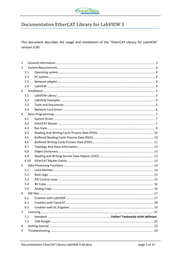
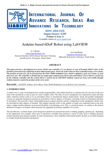
Syringe Pump Technical Bulletin Oct 2020, TB39Figure 8: License AgreementFigure 11: Installation completeFigure 12: Restart computer so registry is readFigure 9: Start installationFigure 10: Installation progress4. Make sure the pump controller is connected tothe computer using the USB cable and thatpower is turned on.5. Start the program press the Windows key andenter Isco Pump Control in the search box andthen press ENTER.6. The main screen will open along with the SerialPort dialog window (Figure 13). The Serial Portdialogue window will only open if there is nocommunication.Figure 13: Serial entry
Syringe Pump Technical Bulletin Oct 2020, TB397. The COM port should be changed to match thenumber you recorded earlier (Device Manager-Com & LPT).8. The Baud Rate and Pump Controller ID should beset to match those in the controller. To check thepump controller settings press MENU, A, 1 toshow the serial setting screen (Figure 14). It isrecommend to use the 38, 4000 setting for theBaud Rate.Figure 16: Main screen in remote modeFigure 14: Controller serial values entry screen9. When all the values match press the FINISHED key.The program then displays all pumps connectedand is in local mode (Figure 15). In local mode thevalues are constantly updated but no changes can bemade from the computer.11. Clicking the SETUP button will switch to the setupscreen (Figure 17).12. On this screen you can give the pump a name,select the units for flow rate and pressure, theserial parameters, and the operating mode of thepumps.In Figure 17 the drop down arrow for the modeselect for pump A has been selected and the 4options are shown. The check mark shows thecurrently selected mode and the yellow highlightshow the mode that will be selected if ENTER or themouse button is clicked.Figure 15: Main screen in local mode10. Pressing the Remote/Local key switches to theRemote mode (Figure 16). Items on coloredbackgrounds can now be selected or the valueschanges.Figure 17: Setup ScreenThe limits screen (Figure 18) allows the setting ofthe upper and lower pressure and flow rate limits,maximum flow rate when pump is in constantpressure mode, and selecting the various alarmfunctions. (See section 3.8.7 LIMITS in D seriesInstallation and Operations Guide for details onlimits and alarms).
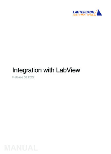
Syringe Pump Technical Bulletin Oct 2020, TB39NoteTo save any changes, the APPLY CHANGES button mustbe clicked.continuous constant pressure and Pumps C&D arein continuous constant flow.Figure 20: Main screen when two continuous flowsystems are in useFigure 18: Limits screenIf additional pumps are connected to thecontroller they will also appear as shown in Figure19.The fluid level in pump and valve status areshown for each connected pump as shown in Figure21.NotePumps A & B are linked because they are incontinuous constant pressure mode. Pumps C and Dare shown in independent mode.Figure 21: Valve and pump symbolsPump Data CapturePump data can be captured and stored in a .csvfile for later analysis. The name of the file can beentered and the time between samples selected. Themaximum data rate depends on the communicationsbaud rate and the overall speed of the computer, buttypically should be 200 msec or higher. Theparameters are set in the upper right corner of therun screen (Figure 22). When imported into Excel,the data will appear as shown in Figure 22. Thecolumn labels are stored in the file each time theSTART button is pushed.Figure 19: Main screen with 4 pumps connected.A&B are in continuous mode.If four pumps are connected and run as twocontinuous flow systems the screen would appear(Figure 20). In this example, Pumps A&B are inFigure 22: Data capture entry on run screen
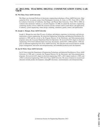
Syringe Pump Technical Bulletin Oct 2020, TB39Figure 23: .CSV data file after import to ExcelRevised Oct 2020Teledyne ISCOP.O. Box 82531, Lincoln, Nebraska, 68501 USAToll-free: (800) 775-2965 Phone: (402) 464-0231 Fax: (402) 465-3001E-mail: IscoService@teledyne.comTeledyne ISCO is continually improving its products and reserves the right to change productspecifications, replacement parts, schematics, and instructions without notice.Use and Disclosure of DataInformation contained herein is classified as EAR99 underthe U.S. Export Administration Regulations.Export, reexport or diversion contrary to U.S. law is prohibited.
Syringe Pump Technical Bulletin Oct 2020, TB39 7. The COM port should be changed to match the number you recorded earlier (Device Man-ager-Com & LPT). 8. The Baud Rate and Pump Controller ID should be set to match those in the controller. To check the pump controller settings press MENU, A, 1 to show the serial setting screen (Figure 14). It is