Transcription
AC 2012-2936: TEACHING DIGITAL COMMUNICATION USING LABVIEWDr. Wei Zhan, Texas A&M UniversityWei Zhan is an Assistant Professor of electronics engineering technology at Texas A&M University. Zhanearned his D.Sc. in systems science from Washington University, St. Louis, in 1991. From 1991 to 1995,he worked at University of California, San Diego, and Wayne State University. From 1995 to 2006, heworked in the automotive industry as a System Engineer. In 2006, he joined the electronics engineeringyechnology faculty at Texas A&M. His research activities include control system theory and applicationsto industry, system engineering, robust design, modeling, simulation, quality control, and optimization.Dr. Joseph A. Morgan, Texas A&M UniversityJoseph A. Morgan has more than 20 years of military and industry experience in electronics and telecommunications systems engineering. He joined the Engineering Technology and Industrial Distribution Department in 1989 and has served as the Program Director of the Electronics and Telecommunicationsprograms and as the Associate Department Head for Operations. He received his B.S. degree in electricalengineering (1975) from California State University, Sacramento, and his M.S. (1980) and D.E. (1983) degrees in industrial engineering from Texas A&M University. His education and research interests includeproject management, innovation and entrepreneurship, and embedded product/system development.Dr. Jay R. Porter, Texas A&M UniversityJay R. Porter joined the Department of Engineering Technology and Industrial Distribution at Texas A&MUniversity in 1998 and is currently the Program Director for the Electronics and Telecommunicationsprograms. He received a B.S. degree in electrical engineering (1987), a M.S. degree in physics (1989), anda Ph.D. in electrical engineering (1993) from Texas A&M University. His areas of interest in research andeducation include product development, analog/RF electronics, instrumentation, and entrepreneurship.Page 25.1248.1c American Society for Engineering Education, 2012
Teaching Digital Communication using LabVIEWAbstractIn response to the needs of the power industry, the Electronics Engineering Technology programat Texas A&M University has been revamping the instrumentation course to focus on digitalinstrumentation, in particular, digital communication protocols. Modbus was selected for itssimplicity, open architecture, and wide use in industry as the communication protocol for twocourse projects in an instrumentation course.LabVIEW was extensively used in the laboratory sessions, which better prepared students for thecourse projects. Two course projects were designed to familiarize the students with virtualinstrumentation, data acquisition, Modbus communication, and simple closed loop control. Oneinvolved the instrumentation and control of a brushed DC permanent magnetic motor; the otherinvolved the instrumentation and control of a small scale temperature chamber. Students usedone computer, functioning as a Modbus slave, to measure the motor speed or temperature insidethe chamber and to turn the motor or the light bulbs on and off. Another computer, functioningas a Modbus master, reads the measurements using Modbus communication protocol via RS-485wires, compared the measurements to the set points, made control decisions, and sent thecommands to the Modbus slave for actuation. Details of the course projects will be discussed inthis article.Page 25.1248.2
1. IntroductionAs a practical discipline, engineering requires hands-on experience. There have been extensivediscussions on the role of laboratory, and how to strike a balance between theory and practice8.Laboratories can be expensive and time consuming. Theoretic study can be difficult tounderstand, and boring. But, without the fundamental understanding of theories, laboratory workcan become inefficient trial-and-errors. One of the solutions proposed by many scholars is to usetools such as LabVIEW throughout the engineering education programs.Page 25.1248.3LabVIEW (short for Laboratory Virtual Instrumentation Engineering Workbench), developed byNational Instruments (NI), is a data acquisition, instrumentation, and control programming toolwidely used in industry. LabVIEW’s graphical programming environment with many softwarefeatures and hardware options is the main reason for its increasing popularity over the last twodecades. Many engineers use LabVIEW for testing and rapid prototyping in their productdevelopment process. In higher education institutes, LabVIEW can be used to help studentsunderstand complex theories and make a connection to practical problems. Even thoughinstrumentation is mainly a subject of electrical engineering, it is used in almost everyengineering major. Many scholars have explored the various capabilities of LabVIEW inlaboratory experimentation and data acquisition. The use of LabVIEW in the engineeringcurriculum for data acquisition, instrument, and control has been well documented. LabVIEWwas used to teach Fourier transform3, analog to digital converter9, thermodynamics11, vibrationmeasurement14, telephone line encoder and decoder16, material testing24, biomedicalengineering32, DSP33, signals and systems34, dynamic systems5, and liquid level control35. It alsohas been used as a tool to teach engineering students introductory software programming18,22,problem solving12, and digital logic25. Many multidisciplinary courses and projects usedLabVIEW as the data acquisition tool10. Porter et al.26 used LabVIEW as a means to linksimulation and laboratory experiments and as a tool for troubleshooting measurement systems.There were several implementations of LabVIEW remote panels and Runtime engine for remoteaccess to laboratory through the Internet, for purposes such as distance education2,13,23,29.Naghedolfeizi et al.19 conducted an intensive survey on the subject of web-enabled technologies,including LabVIEW, to build remote experiments. Arthur and Sexton1 used LabVIEW toupgrade their energy laboratory. With LabVIEW, they were able to convert an old steam powerplant and cooling tower into a state-of-the-art control system. Quinn discussed the use ofLabVIEW to provide early, continuous and significant laboratory experiences for all engineeringstudents throughout the freshman and sophomore years at Drexel University28. There wereseveral other efforts made by scholars to incorporate LabVIEW into the entire curriculum4,6,15,36. Erwin et al.7 proposed to use LabVIEW together with LEGO materials starting fromkindergarten to graduate school. The conclusions from these articles were overwhelminglypositive. Students learned instrumentation concepts through hands-on experience usingLabVIEW.
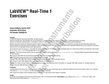
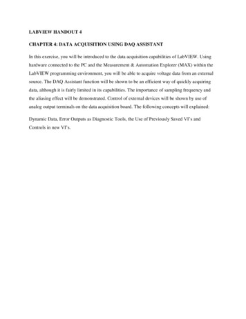
In response to the needs of industry, the Electronics Engineering Technology (EET) program atTexas A&M University is moving its focus towards product/system development. As part of thiscurriculum modification effort, the instrumentation course (ENTC359) has been revamped tofocus on digital instrumentation27. A new course project was created to provide students withhands-on experience in digital communication protocol. The course project has four majorcomponents: a LabVIEW20 based closed loop control system design using the Modbus17 digitalcommunication protocol; hardware design to replace the Modbus slave with a PCB; softwaredesign for the Modbus slave; and system integration. The focus of this article is on the firstcomponent, i.e., LabVIEW based closed loop control using Modbus communication protocol.LabVIEW was chosen to be the tool for the course project because it can provide hands-onexperiences for students, which is particularly important for engineering technology programs.Another reason for using LabVIEW was that it was being used by several other courses in theEET program, as part of the curriculum integration effort, LabVIEW was selected to be one ofthe software tools used throughout the entire curriculum.Modbus is a serial digital communication protocol developed by Modicon in 197917. It is simple,robust, and widely used in industry. As a result, it has become the de facto standard in industry.It is an open architecture with specifications freely accessible on the web. Other digitalcommunication protocols were also considered with the limitation to open architectures.Foundation Fieldbus and DNP3 were among the candidates for the course projects. Even thoughthey are both open architectures, users need to pay membership fees to obtain copies of thespecifications. The actual implementation could be more complicated than Modbus. It was alsofound that the NI website had free Modbus modules for LabVIEW. All these contributed to thedecision to use Modbus and LabVIEW in the course project. Modbus is an application layermessaging protocol that provides client/server communication.Page 25.1248.4Figure 1. An example of Modbus network17
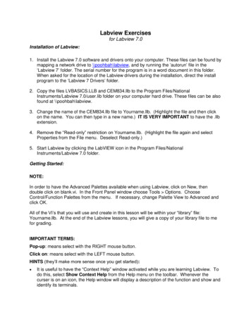
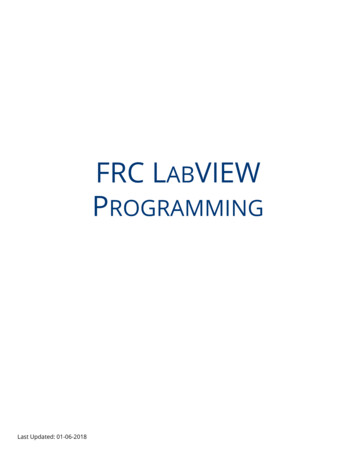
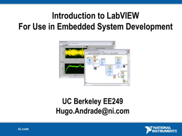
A typical Modbus network is showed in Fig. 117. A Modbus serial line Protocol Data Unit(PDU) consists of address, function code, data, and CRC (or LRC) as shown in Fig. 2.Figure 2. Modbus frame over serial lineThe other components of the project, i.e, the hardware design, software design, and systemintegration were designed to familiarize students with the product/system development process.The rest of the paper is organized as follows: Section 2 contains the details of the courseprojects; Section 3 contains the use of LabVIEW in the course projects and the laboratoriesbefore the projects; Section 4 contains the conclusions and future work.2. Course projectsInspired by the work of Arthur and Sexton1, three old temperature chambers in good workingcondition were converted to a closed loop system using LabVIEW and a data acquisition card(DAQ). Fig. 3 shows one of the temperature chambers.Figure 3. Temperature chamberPage 25.1248.5DC permanent magnetic motors are widely used in industry for their low cost, ease of control,and reliable performance30. They are also used successfully by other engineering educators31 forcurriculum improvement purposes. The motor principles can be explained in a straightforwardway. Digital controllers, with software or hardware implementation, can be implemented tocontrol the speed. They require instrumentation to measure the speed for closed loop controldesign. All these make the motor a good candidate for curriculum integration. Based on theseconsiderations, several low cost motors, including the IG220019*00015R motor from Digilent,were tested as the common platform for vertical curriculum integration. In the spring semester of2010, a motor control system, shown in Fig. 4, was added so that half of the class could work onthe temperature control systems and the other half could work on the motor control systems.
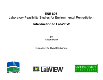
Figure 4. Motor control systemThe addition of the motor control systems was based on the following reasons: there were onlythree temperature chambers, and teams sharing the temperature chambers had conflicts in usingthem; motor control was used in other courses of the EET program, thus contributing to thecurriculum integration effort; The temperature chambers and motor control systems havedifferent types of inputs and output, thus giving student more options to learn and gain hands-onexperiences.The setup of these two systems is illustrated in Fig. 5. For the temperature control system, atemperature chamber is provided. Inside the chamber, a temperature sensor circuit, consisting ofa constant voltage potentiometer circuit, is installed, which allows the user to monitor thetemperature inside the chamber. Two light bulbs can be turned on and off by sending digitalsignals to the switches. They can be used to increase the temperature inside the chamber. A fan,whose speed can be controlled by a DC permanent magnetic motor using PWM, is installed atone end of the chamber. The cooling rate can be adjusted by varying the motor speed. Both thelights, motor and temperature sensor circuit need to have external power sources, which are notshown in Fig. 5.To develop a closed loop temperature control system, a LabVIEW VI needs to be created bystudents. The VI uses an analog input channel for temperature reading, two digital outputchannels for turning the light bulbs on and off, and a digital output channel for PWM control ofthe cooling fan. A DAQ card is provided for data acquisition.Page 25.1248.6For the motor speed control system, a DC PM brushed motor and a motor control board areprovided. The motor has two terminals for power and an encoder for speed measurement. Themotor control board allows the user to drive the motor with a PWM signal and read the encodersignal. A LabVIEW VI with a counter channel for encoder signal and a digital output channel formotor PWM needs to be created. A timed loop can be used to calculate the motor speed using the
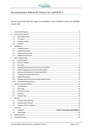
digital signal from the encoder. The motor also has an external power source, which is not shownin Fig. 5.ModbusslaveRS485ModbusmasterModbusslavePWM controlMfanlight1light2ModbusmasterRS485Speed feedbackTemp.sensorTemperature controlMotor speed controlFigure 5. Setups of the temperature chamber and motor control systemsThe first stage of the course projects requires the students to use a NI DAQ (PCI-6251) to actuatethe control (turn on the lights and PWM the motor) and read the feedback signals (voltage fromthe temperature sensor circuit and encoder from motor). The Modbus master and slave are ran ontwo separate desktops in the LabVIEW environment. The communication between the masterand slave is through an RS-485 bus cable. The slave reads the desired temperature or motorspeed every second from the master. The controllers reside in the slave VI. The feedback andactuation are done in the slave through the DAQ card. The slave also performs tasks such asdigital filtering, conversion from voltage to temperature, and counting pulses for speedcalculation. The slave sends the current output (temperature or motor speed) to the master. Themaster allows the user to set a profile, which the user specifies by defining the discrete points onthe profile and connecting two adjacent point with a line segment as illustrated in Fig. 6. Theprofile can be the desired temperature or motor speed. Various graphical and numerical displaysare also required on the front panel of the master and slave.Temperature (C ) /Motor speed (rpm)Time (sec)Page 25.1248.7Figure 6. The temperature/speed profile created on the front panel of the master VI
After successfully implementing the LabVIEW based closed loop control systems, students thendesign a PCB to replace all the functionalities of the slave.3. LabVIEW based closed loop control and laboratories lead to the projectsEET program at Texas A&M University uses LabVIEW in several courses: ENTC 359, ENTC355, ENTC 352. ENTC was one of the first courses in which students were exposed to theLabVIEW software. Students then use LabVIEW in the other courses. The idea is throughrepeated exposure to LabVIEW in various courses students will master the software and be ableto use it effectively to solve engineering problems. In ENTC 359, the basic concept of virtualinstrumentation is taught followed by online LabVIEW training modules21.One of the issues we had with the ENTC 359 course project was that many student teams ran outof time for the course project27. To help students focus on the main topic of digitalcommunication and product development process, the laboratories were revised so that studentswere better prepared for the course projects. Five laboratories were created in order to familiarizestudents with using LabVIEW to read analog and digital inputs and to send analog and digitaloutputs.Lab 1: Online LabVIEW training21. Only the first six modules were used in ENTC 359:LabVIEW Environment; Passing Data and Debugging; Loops; Timing and Storing Data; Array,Clusters, and Text Based Nodes; and Variables.Lab 2: Data acquisition using LabVIEW DAQ: Analog input. A constant potentiometer circuitwas used for temperature and light intensity measurements.Lab 3: Using LabVIEW analog or digital output to turn a light on and off followed bycombination with Lab 1 to use temperature or light intensity to turn the light on/off.Lab 4: Develop a closed loop temperature control system with a single VI. A user definedtemperature profile is part of the VI.Lab 5: Develop a closed loop motor speed control system with a single VI. A user defined motorspeed profile is part of the VI.Page 25.1248.8After these five labs, students were asked to download the Modbus master and slave VI from theNI website. Simple communication between two desktops can be established using the exampleVI, whose front panels are shown in Fig. 7. In the screen shoot captured in Fig. 7, the master hadfour coils and four registers. They have the values of “False, False, False, True” and “0,4,7,0”.These values were transmitted through an RS 485 communication bus to the slave and displayedon the front panel. The user also set the values for four discrete inputs and input registers to“False, True, False, False” and “2,0,5,0”. These values were also transmitted to the Modbusmaster. The NI Modbus module provided a basic platform for digital communication betweenthe two computers. The students can then build a closed loop temperature or motor speed controlsystem using this platform as a required task for the course project.
Figure 7. Modbus master and slave front panelsPage 25.1248.9The Modbus master and slave VIs are not only a starting point for students to build their closedloop control systems, they are also a learning tool for Modbus. The details of forming theModbus PDU can be added to the front panel. The output from the slave VI can be displayed inan oscilloscope, which allows students to understand the Modbus message down to single bits asillustrated in Fig. 8.
Figure 8. Modbus message captured with an oscilloscopeThe front panel of a Modbus master VI created by a student team is shown in Fig. 9.Page 25.1248.10Figure 9. Front panel of a Modbus master VI created by a student team
The temperature profile (white trace) and the actual temperature (read trace) were plotted on thesame chart. The error was also displayed on the front panel. The students taking ENTC 359 hadnot taken the Controls class, therefore their control algorithm was basically logics based oncommon sense. A typical control logic looks like this:If temperature desired temperature – 0.5 oCThen turn two light bulbs on and turn the fan motor off;Else if temperature desired temperatureThen turn one light bulb on and turn the fan motor off;Else if temperature desired temperature 0.3 oCThen turn both light bulbs off and send a high PWM duty cycle to the fan motor;Else turn both light bulbs off and send a low PWM duty cycle to the fan motor.Some students also figured out how to avoid the flicking of the lights by adding a hysteresis tothe control logic. It is planned as a part of the curriculum integration effort that the temperatureor motor control systems be used in the laboratories of the subsequent Controls course, wherePID control can be applied to the controller to further improve the result.A software bug was identified for LabVIEW (version 2010 and older), where a local variableinside a case structure would not work as it was supposed to. This issue was reported to NI.Another issue with the LabVIEW Modbus was that the bus only allows one slave as opposed tomultiple slaves. This prevented us from controlling both the temperature chamber and motorspeed with one master and two slaves.4. Conclusions and future workA LabVIEW based Modbus communication project was created for an instrumentation course.Five laboratory classes were created to support the course project. Three small-scale temperaturechambers were upgraded with the LabVIEW based data acquisition and control system. A DCpermanent magnetic motor control system was developed to be an alternative course project. Thetwo systems offer more options to students for learning different aspects of instrumentation.Students learned LabVIEW, data acquisition, instrumentation, and Modbus communicationprotocol in this project. It has become a core piece in the overall curriculum integration effort forthe EET program at Texas A&M University.Page 25.1248.11After the successful completion of the LabVIEW based control systems, students were thentasked to design a printed circuit board, including a micro-controller on the board, to replace theLabVIEW-based Modbus slave. Instead of using National Instrumentation’s Data AcquisitionCard (DAQ card), sensor circuits, signal conditioning circuits, and a micro-controller were usedfor data acquisition, Modbus communication, and controlling of the motor or light bulbs.
As an effort to continually improve our education program, the effectiveness of the courseprojects will be quantitatively and qualitatively monitored through student and faculty surveys,feedback from former students, and results of examinations. These results will be shared withother educators in a future publication.References1. Arthur, J. H. and Sexton, M. R., “Labview Application: Energy Laboratory Upgrade,” Proceedings ofASEE Annual Conference, 2002.2. Akinwale, O., Kehinde, L., Ayodele,K. P., Jubril, A. M., Jonah,O. P., Ilori, S., and Chen, X., “ALabview-Based On-Line Robotic Arm for Students' Laboratory,” Proceedings of ASEE AnnualConference, 2009.3. Avitabile, P., Hodgkins, J., and Van Zandt, T., “Innovative Teaching of Fourier Series UsingLabview,” Proceedings of ASEE Annual Conference, 2006.4. Barat, R., Federici, J., Johnson, A., Grebel, H., and Chang, T., “Optical Science and EngineeringCurriculum at NJIT,” Journal of Engineering Education, 1998, pp.575-582.5. Bowen, K. and O'Malley, M., “Haptic Interfaces for a Labview-Based System Dynamics Course,”Proceedings of ASEE Annual Conference, 2006.6. Cui, S., Wang, Y., Zhang, Y., and Akujuobi, C., “Laboratories Enhancement with Labview BasedGraphical Development Tools,” Proceedings of ASEE Annual Conference, 2008.7. Erwin, B., Cyr, M., and Rogers, C., “LEGO engineer and ROBOLAB: Teaching engineering withLabVIEW from kindergarten to graduate school,” International Journal of Engineering Education,16(3), 2000, pp. 181–92.8. Feisel, L. D. and Rosa, A. J., “The Role of the Laboratory in Undergraduate Engineering Education,”Journal of Engineering Education, 2005, pp. 121-130.9. Franklin, B. E., Akujuobi, C. M., and Ali, W., “ADC Automated Testing Using LabView Software,”Proceedings of ASEE Annual Conference, 2004.10. Globig, J. E., “An Interdisciplinary, LabVIEW Based, Data Acquisition and Measurements Course,”Proceedings of ASEE Annual Conference, 2003.11. Hines, J. W., Oro, R., and Sharara, Y., “Development of an Inexpensive LabView-BasedRefrigeration Cycle Laboratory,” Proceedings of ASEE Annual Conference, 2003.12. Hrynuk, J., Pennington, M., Illig, D., and Dempsey, J. P., “An Introductory Computer CourseTeaching Matlab and Labview,” Proceedings of ASEE Annual Conference, 2008.13. Khan, S., Farahmand, F., and Moslehpour, S., “A Labview Based Integrated Virtual LearningPlatform,” Proceedings of ASEE Annual Conference, 2010.Page 25.1248.1214. Kiritsis, N., Huang, Y. W., and Ayrapetyan, D., “A Multi-Purpose Vibration Experiment UsingLabview,” Proceedings of ASEE Annual Conference, 2003.
15. Lohani, V., Delgoshaei, P., and Green, C., “Integrating Labview and Real-Time Monitoring intoEngineering Instruction,” Proceedings of ASEE Annual Conference, 2009.16. Loker, D. R., “DTMF Encoder and Decoder using LabVIEW,” Proceedings of ASEE AnnualConference, 2002.17. Modbus-IDA, Modbus Application Protocol Specification, V1.1b, December 28, 2006, pp. 1-51. Lastaccessed on January, 6, 2012:http://www.modbus.org/docs/Modbus Application Protocol V1 1b.pdf18. Neuman, C., Lieberman, D., Engelberg, D., Flamholz, A., Marchese, P., Tremberger, G., and Cheung,T., “Labview Graphical Programming in an Introductory Engineering Physics Course,” Proceedingsof ASEE Annual Conference, 2006.19. Naghedolfeizi, M., Arora, S., and Garcia, S., “Survey of LabVIEW Technologies for BuildingWeb/Internet-Enabled Experimental Setups,” Proceedings of ASEE Annual Conference, 2002.20. National Instruments, “LabVIEW User Manual,” April 2003.21. National Instruments, “Getting Started NI LabVIEW Student Training,” website last accessed onJanuary 10, 2. Navaee, S., “Computing and Programming with LabVIEW,” Proceedings of ASEE AnnualConference, 2004.23. Ogot, M., Elliott, G., and Glumac, N., “An Assessment of In-Person and Remotely OperatedLaboratories,” Journal of Engineering Education, January 2003, pp. 57-64.24. Orabi, I. I., “Application of LabVIEW for Undergraduate Lab Experiments on Materials Testing,”Proceedings of ASEE Annual Conference, 2002.25. Perales, T., Morgan, J. A., and Porter, J. R., “A Labview Fpga Toolkit To Teach Digital LogicDesign,” Proceedings of ASEE Annual Conference, 2009.26. Porter, J.R., “Linking Simulation Tools to Laboratory Experiments using LabVIEW, “ InternationalJournal of Engineering Education, Vol. 21, 1, January 2005.27. Porter, J. R., Morgan, J. A., and Zhan, W., “Development of a “Smart” Sensor: An IntegratedInstrumentation Course Project”, Proceedings of the 2009 ASEE Annual Conference.28. Quinn, R. G., “The E(4) Introductory Engineering Test, Design and Simulation Laboratory,” Journalof Engineering Education, 1993, pp. 224-226.29. Rézaei, E. K. and Kolla, S. R., “Internet-Based On/Off Controller Using LabVIEW,” Proceedings ofASEE Annual Conference, 2003.30. Santan J., Naredo J.L., Sandoval, F., Grout, I., and Argueta, O.J., “Simulation and construction of aspeed control for a DC series motor,” Mechatronics, Vol. 12, 2002, pp. 1145-1156.Page 25.1248.1331. Schubert, T. F., Jacobitz, F. G., and Kim E. M., “Exploring the Basic Principles of Electric Motorsand Generators With a Low-Cost Sophomore-Level Experiment,” IEEE Trans. Education, V0l. 52,No. 1, 2009, pp. 57-65.
32. Sharad, S., “A Biomedical Engineering Startup Kit For Labview,” Proceedings of ASEE AnnualConference, 2008.33. Tanyel, M., “Putting Bells & Whistles on DSP Toolkit of LabVIEW,” Proceedings of ASEE AnnualConference, 2011.34. Thiagarajan, J. J., Tsakalis, K., Spanias, A., and Thornburg, H., “On the Use of Labview in Signalsand Systems,” Proceedings of ASEE Annual Conference, 2009.35. Wagoner, J. D. and Macia, N. F., “Automatic Liquid Level Controller Using a Labview Based PC,”Proceedings of ASEE Annual Conference, 2004.36. Yang, B., Adams, R. D., and Ball, A. K., “Incorporating LabView(R) in Junior Electrical EngineeringLabs,” Proceedings of ASEE Annual Conference, 2011.Page 25.1248.14
Arthur and Sexton 1 used LabVIEW to upgrade their energy laboratory. With LabVIEW, they were able to convert an old steam power plant and cooling tower into a state -of -the -art control system. Quinn discussed the use of LabVIEW to provide early , continuous an