Transcription
GETTING STARTEDNI SMD-7620/7621 StepperDrives and NI 9512 C SeriesModulesNote If you are a new user of LabVIEW or are unfamiliar with LabVIEW, refer tothe Getting Started with LabVIEW manual for information about LabVIEW andLabVIEW terminology.This document explains how to install and configure the NI SMD-7620/7621 stepper drives foruse with the NI 9512 C Series drive interface module.ContentsWhat You Need to Get Started . 2Hardware . 2Software. 3Related Documentation . 3Hardware Installation and Configuration . 4Step 1: Set Up the CompactRIO System . 4Step 2: Connect the NI 9512 to the 37-Pin Terminal Block. 6Step 3: Connect the 37-Pin Terminal Block to the 24 V Power Supply . 6Step 4: Connect the Drive Command Signals . 7Step 5: Connect the Drive Enable Signal . 7Step 6: (Optional) Connect the Drive Fault Signal. 7Step 7: (Optional) Connect the Encoder Signals . 8Step 8: Connect the NI SMD-7620/7621 to AC Power. 8Step 9: Connect the SMD-7620/7621 to the Motor. 9Step 10: Connect the NI SMD-7620/7621 to the Network . 11Step 11: Power on the Drive and Verify Connections. 12Software Installation and Configuration. 12Step 1: Install Software on and Configure the NI RT Controller . 12Step 2: Create a Project in Scan Interface Mode . 14Step 3: Add Resources to the Project . 14Step 4: Configure the NI 9512 Axis . 16Step 5: Configure the Drive Using the NI Stepper Configuration Utility . 19Step 6: Enable and Test the Drive Using LabVIEW . 20Worldwide Support and Services . 21
What You Need to Get StartedYou need the following items to get started.Hardware NI 9512 C Series stepper drive interface module NI real-time controller–CompactRIO controller and chassis that support the RIO Scan InterfaceTip To determine if your controller and chassis support the RIO Scan Interface goto ni.com/info and enter the Info Code rdsoftwareversion.or–NI 9144 distributed chassis and compatible RT controller 24 V power supply (such as the NI PS-15) for the CompactRIO controller(NI part number 781093-01) Separate 24 V power supply for the NI 9512 (such as the NI PS-15) NI SMD-7620/7621 stepper drive NI or third-party stepper motorNote NI offers stepper motors matched to the NI SMD-7620/7621. Refer toni.com/motion for motor options. National Instruments highly recommends usingthese motors for the best user experience. (Optional) ENC-7741 encoder for ST23 motors (NI part number 748992-01) or ENC-7742encoder for ST34 motors (NI part number 748993-01) NI-7748 encoder cable to connect the encoder to the NI 951x terminal block(NI part number 748994-01) Ethernet connection and cable for the CompactRIO controller Ethernet connection and cable for the NI SMD-7620/7621 AC input cable for the NI SMD-7620/7621 NI 951x Cable and Terminal Block bundle (NI part number 780553-01)2 ni.com Getting Started with NI SMD-7620/7621 and NI 9512 Modules
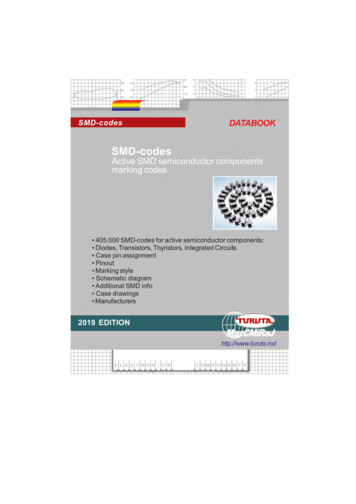
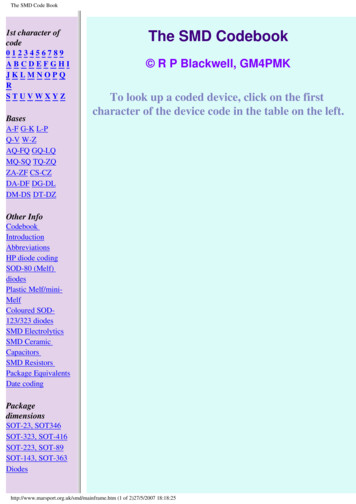
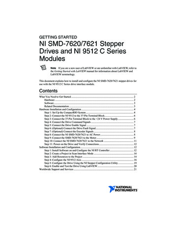
Software LabVIEW 2010 or later LabVIEW 2010 Real-Time Module or later LabVIEW 2010 NI SoftMotion Module or later NI-RIO 3.5.1 or later NI Stepper Configuration UtilityFigure 1 shows a simplified connection diagram.Figure 1. NI 9512 to NI SMD-7620/7621 Connections 24 V Power Supply(NI PS-15 Shown)37-pin Terminal 24 V Power SupplyBlock(NI PS-15 Shown)EthernetCableNI RT Controller(NI cRIO-9014 shown)and NI 9512 ModuleI/OConnectionsNI SMD-7620/7621EthernetCableAC InputEncoderConnectionsNI Stepper MotorRelated DocumentationThe following documents contain additional information that you may find helpful. Allreferenced documents ship with the product and are available at ni.com/manuals. Operating instructions for the controller and C Series module. NI SMD-7620/7621 User Manual LabVIEW NI SoftMotion Module Help—Use this help file to learn about using theNI SoftMotion Module in LabVIEW including information about function blocks andusing the NI SoftMotion Module with the LabVIEW Project. To access this help file fromLabVIEW, select Help»LabVIEW Help, then expand the LabVIEW NI SoftMotionModule book on the Contents tab. LabVIEW Help—Use the LabVIEW Help to access information about LabVIEWprogramming concepts, step-by-step instructions for using LabVIEW, and referenceinformation about LabVIEW VIs, functions, palettes, menus, tools, properties, methods,Getting Started with NI SMD-7620/7621 and NI 9512 Modules National Instruments 3
events, dialog boxes, and so on. The LabVIEW Help also lists the LabVIEW documentationresources available from National Instruments. Access the LabVIEW Help by selectingHelp»LabVIEW Help. Getting Started with LabVIEW—Use this document as a tutorial to familiarize yourselfwith the LabVIEW graphical programming environment and the basic LabVIEW featuresyou use to build data acquisition and instrument control applications. Access the GettingStarted with LabVIEW PDF by selecting Start»All Programs»National Instruments»LabVIEW»LabVIEW Manuals»LV Getting Started.pdf.Hardware Installation and ConfigurationThis section covers the hardware setup for the CompactRIO system, NI 9512 C Series module,and NI SMD-7620/7621 stepper drive.Step 1: Set Up the CompactRIO SystemComplete the following steps to set up the CompactRIO hardware.1.Install the real-time CompactRIO controller on the chassis if you are not using an integratedcontroller and chassis.Write down the controller serial number before installing the controller ontothe chassis. You will be unable to read the serial number after you install thecontroller.Notea.4 Make sure that no power is connected to the controller or the chassis.ni.com Getting Started with NI SMD-7620/7621 and NI 9512 Modules
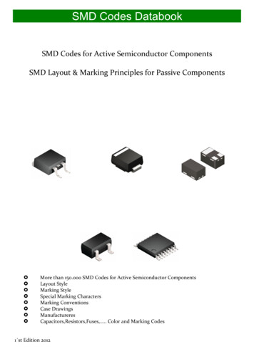
b.Align the controller with the chassis as shown in Figure 2.Figure 2. Installing the Controller on the Chassis (Eight-Slot Chassis Shown)514321232.ControllerCaptive ScrewsController Slot45Reconfigurable Embedded ChassisGrounding Screwc.Slide the controller onto the controller slot on the chassis. Press firmly to ensure thechassis connector and the controller connector are mated.d.Using a number 2 Phillips screwdriver, tighten the two captive screws on the front ofthe controller.Connect the controller to a power supply and an Ethernet network on the same subnet asthe development computer. Refer to the controller operating instructions for informationabout wiring the controller to the power supply and Ethernet network.Note Do not plug in or turn on any power to the system until after you completeStep 11: Power on the Drive and Verify Connections.3.Install the NI 9512 module in slot 1, 2, 3, or 4 of the chassis.Getting Started with NI SMD-7620/7621 and NI 9512 Modules National Instruments 5
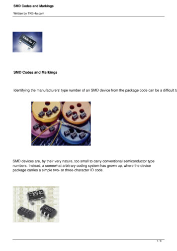
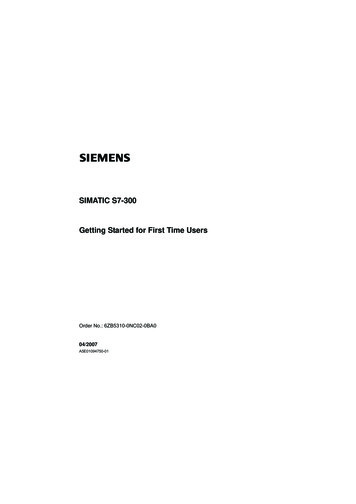
Step 2: Connect the NI 9512 to the 37-Pin TerminalBlock1.Connect the MDR and DSUB connectors on the NI 951x Y-cable to the MDR and DSUBconnectors on the NI 9512 module.2.Connect the 37-pin DSUB to the DSUB connector on the NI 951x terminal block.Figure 3 shows the 37-pin terminal block pin assignments.Figure 3. NI 9512 37-Pin Terminal Block Pin AssignmentsDirection (CCW)–†36Digital Input 2†Step (CW)–†37Digital Input 3†3518 GNDDrive Enable†3417Shield†Indicates DSUB connector signals.COM†3316Step (CW) †Reserved3215COM†Direction (CCW) Reserved3114†Digital Input 1Encoder 0 Phase B–3013†Position Capture2912Vsup†Encoder 0 Phase B 2811Digital Output 0†Encoder 0 Phase A–2710ReservedEncoder 0 Phase A 269ReservedCOM258Position CompareVsupReserved247 5V OUT236COMReserved225Encoder 0 Index–Reverse Limit214COMEncoder 0 Index Digital Output 1†20Digital Input 0193COM2Home1Forward LimitStep 3: Connect the 37-Pin Terminal Block to the 24 V Power SupplyDo not plug in or turn on the power supply until after you complete Step 11:Power on the Drive and Verify Connections.Note1.Connect the V terminal from the 24 V power supply to one of the two Vsup inputs on the37-pin terminal block. The 37-pin terminal block provides a Vsup input for the NI 9512 onpin 14 and pin 22.2.Connect the V- terminal from the 24 V power supply to one of the COM terminals on the37-pin terminal block. The 37-pin terminal block provides COM on pins 3, 5, 8, 17, 24,and 32.6 ni.com Getting Started with NI SMD-7620/7621 and NI 9512 Modules
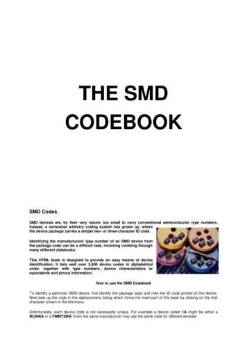
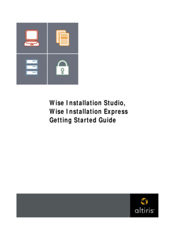
Step 4: Connect the Drive Command SignalsComplete the following steps to connect the Drive Command signals to the NI 9512 terminalblock.1.Connect the SMD-7620/7621 X1/STEP- terminal (pin 2) to the 37-pin terminal blockStep (CW) terminal (pin 18).2.Connect the SMD-7620/7621 X2/DIR- terminal (pin 4) to the 37-pin terminal blockDirection (CCW) terminal (pin 16).3.Connect the SMD-7620/7621 X1/STEP terminal (pin 1) and X2/DIR terminal (pin 3) tothe 37-pin terminal block 5V OUT terminal (pin 9).Figure 4 shows the SMD-7620/7621 Drive Command and I/O Connector location and pinout.Figure 4. SMD-7620/7621 Drive Command and I/O ConnectorL NA A- B B-X1/STEP X1/STEP–X2/DIR X2/DIR–X3/EN X3/EN–GND 5V OUT(100 mA MAX)123456789101112131415ReservedReservedY1 Y1–Y2 Y2–ReservedStep 5: Connect the Drive Enable SignalComplete the following steps to connect the Drive Enable signal, which controls the enablefunction of the drive:1.Connect the X3/EN- terminal (pin 6) to the 37-pin terminal block COM terminal (pin 5).2.Connect the X3/EN terminal (pin 5) to the 37-pin terminal block Drive Enable terminal(pin 33).Step 6: (Optional) Connect the Drive Fault SignalComplete the following steps to map an NI 9512 digital input to the SMD-7620/7621 Y1programmable output signal to monitor the NI SMD-7620/7621 stepper drive for faults:1.Connect the Y1 terminal (pin 11) to the 37-pin terminal block Vsup terminal (pin 22).2.Connect the Y1- terminal (pin 12) to the 37-pin terminal block DI 0 terminal (pin 4).Getting Started with NI SMD-7620/7621 and NI 9512 Modules National Instruments 7
Step 7: (Optional) Connect the Encoder SignalsIf your motor includes an encoder, complete the following steps to connect the encoder to theNI 951x terminal block:1.Connect one end of the encoder cable to the encoder.2.Cut the 15-pin DSUB connector off of the other end of the cable and expose the encoderwires.3.Connect the encoder wires to the 37-pin terminal block as indicated in Table 1.4.Insulate any unused wires.Table 1. NI SMD-7620/7621 to 37-Pin Terminal Block ConnectionsEncoderSignal NameEncoder CableWire Color37-PinTerminal BlockPin Number37-PinTerminal BlockSignal NameCH Ablue25Encoder 0 Phase A CH A-blue/white26Encoder 0 Phase A-CH Byellow27Encoder 0 Phase B CH B-yellow/white29Encoder 0 Phase B-INDEXorange6Encoder 0 Index INDEX-orange/white7Encoder 0 Index-GNDblack8COM Vccred9 5V OUTStep 8: Connect the NI SMD-7620/7621 to AC PowerNote Do not apply power until after you complete Step 11: Power on the Drive andVerify Connections.Complete the following steps to connect the NI SMD-7620/7621 to AC power.1.Connect an AC input cable to the line, neutral, and protective earth connectors as shown inFigure 5.2.(Optional) Install a fuse on the AC input line as shown. The SMD-7620 contains an internal8 A fast acting fuse. The SMD-7621 contains an internal 3.5 A fast acting fuse. If anexternal fuse is desired, National Instruments recommends a 6 A fast acting fuse for theSMD-7620 and a 3 A fast acting fuse for the SMD-7621 version.3.(Optional) If your application requires EMC compliance, install a Corcom 6ET1 line filterin series with the AC input as shown.8 ni.com Getting Started with NI SMD-7620/7621 and NI 9512 Modules
Refer to the NI SMD-7620/7621 User Manual for more information aboutconnecting to AC power.NoteFigure 5 shows the SMD-7620/7621 Power and Motor Connector location and pinout, withoptional fusing and line filters.Figure 5. SMD-7620/7621 Power and Motor ConnectorL NA A- B B-To Earth GroundTo NeutralTo Line (Hot)Line FilterSurge ProtectorFuseStep 9: Connect the SMD-7620/7621 to the MotorCautionDo not connect or disconnect the motor when the power is on.NI offers NEMA 23 and NEMA 34 stepper motors matched to the SMD-7620/7621. Whenconnecting these motors to the SMD-7620, connect them in parallel as shown in Figure 6.Figure 6. Eight Lead Motor Parallel ConnectionA WhiteBrown8LeadMotorOrangeA–GreenRedBlackBlueB YellowB–Getting Started with NI SMD-7620/7621 and NI 9512 Modules National Instruments 9
When connecting these motors to the SMD-7621, connect them in series as shown in Figure 7.Figure 7. Eight Lead Motor Series ConnectionA WhiteOrange8LeadMotorBrownA–GreenRedB YellowBlackBlueB–For information about connecting third-party motors, refer to theNI SMD-7620/7621 User Manual.NoteFigure 8 shows the NI SMD-7620/7621 motor connections.Figure 8. NI SMD-7620/7621 Motor Connector TerminalL NLINE10 ni.com A A- B B-MOTORGetting Started with NI SMD-7620/7621 and NI 9512 Modules
Step 10: Connect the NI SMD-7620/7621 to the Network1.Connect the NI SMD-7620/7621 to an Ethernet network on the same subnet as thedevelopment computer.2.Set the rotary switch to one of the preset IP addresses or to the F position to configure thedrive to use DHCP.Note This document assumes you have configured the drive for DHCP. Forinformation about other settings refer to the NI SMD-7620/7621 User Manual.Figure 9 shows the NI SMD-7620/7621 NI SMD-7620/7621 IP address selection switch andEthernet connector.Figure 9. NI SMD-7620/7621 IP Selection and Ethernet Connector1L N12A A- B B-IP Address Selection Switch2Ethernet connectorGetting Started with NI SMD-7620/7621 and NI 9512 Modules National Instruments 11
Step 11: Power on the Drive and Verify ConnectionsAfter all hardware connections have been made complete the following steps to confirm thehardware setup.1.Turn on all power supplies and apply AC power.2.Verify that the Drive Status LED on the NI SMD-7620/7621 flashes or is solid green.Figure 10 shows the location of the Drive Status LED.Figure 10. Drive Status LED LocationStatus LEDsIf the Drive Status LED does not flash or turn solid green, turn off all power, verify theconnections, and try again. Refer to the Worldwide Support and Services section for additionaltips.Software Installation and ConfigurationThis section covers installing and configuring software for the NI 9512 C Series module.Note These instructions assume you have installed all required software from theWhat You Need to Get Started section on your development machine.Step 1: Install Software on and Configure the NI RTControllerComplete the following steps to configure the controller and install software on it.Note The Measurement & Automation Explorer (MAX) user interface may notmatch these steps exactly depending on which version of MAX you are using.Verify the NI RT Controller1.12Launch Measurement & Automation Explorer (MAX) on the development computer byclicking the MAX icon on the desktop (), or by szelecting Start»All Programs»National Instruments»Measurement & Automation. ni.com Getting Started with NI SMD-7620/7621 and NI 9512 Modules
2.Expand the Remote Systems tree.3.Highlight the system.Note If you do not see the controller, you may need to disable the firewall on thedevelopment computer. Go to ni.com/info and enter RIOMAXTroubleshootfor more information.4.Verify that the Serial Number in the General Settings section matches the serial numberon the device.If you do not want to format the disk on the controller, eliminating all installed software and files,skip to Install Software on the NI RT Controller.Reformat the NI RT Controller (Optional)1.Set the Safe Mode switch on the controller to the On position.2.Power on the controller. If it is already powered on, press the Reset button on the controllerto reboot it.3.Right-click the controller under Remote Systems in the Configuration pane in MAX andselect Format Disk.4.(Optional) Enable the Keep Network Settings checkbox if you want to retain the sametarget name and IP address.5.Click Format to start formatting the disk.6.When MAX finishes formatting the disk, set the Safe Mode switch to the Off position andclick OK.7.Select the System Settings tab on the bottom and type a descriptive name for the system inthe Hostname field.8.(Optional) Complete this step only if the target has an empty IP address (0.0.0.0). Select theNetwork Settings tab and select DHCP or Link Local from the Configure IPv4 Addresslist to assign an IP address or select the Static to specify a static IP address in the IPv4Address section.9.Click Save on the toolbar and let MAX reboot the system. You may not need to completethis step if you did not change the IP address or name.Install Software on the NI RT Controller1.When the new system name appears under Remote Systems, expand the controller item inthe tree, right-click Software, and select Add/Remove Software.2.Select a recommended software set that includes NI-RIO 3.5.1 or later.3.Click Next.4.Select LabVIEW NI SoftMotion Module from the add-ons list.Note If you are using NI SoftMotion Module 2010 SP1 or earlier, also selectLabVIEW NI SoftMotion Module Scan Engine Support from the list.Getting Started with NI SMD-7620/7621 and NI 9512 Modules National Instruments 13
5.Click Next to install the selected software on the controller. Click Help if you needinformation about installing recommended software sets.6.When the software installation completes, click Finish to reboot the controller.7.Close MAX.Step 2: Create a Project in Scan Interface ModeScan Interface mode enables you to use C Series modules directly from LabVIEW Real-Time.Modules that you use in Scan Interface mode appear directly under the chassis item in theProject Explorer window. Unlike most C Series modules, NI 951x modules are not directlyconfigurable from the Project Explorer window and no I/O variables are directly availableunder the module.Refer to the Select Programming Mode Dialog Box topic of the CompactRIOReference and Procedures (Scan Interface) help file for more information about ScanInterface mode.TipUse a LabVIEW project to manage VIs, targets, and I/O modules on the development computer.Complete the following steps to create a LabVIEW project.1.Launch LabVIEW.2.Select File»Create Project or Project»Create Project to display the Create Projectdialog box. You can also click the Create Project button on the Getting Started window.The Create Project dialog box includes a list of templates and sample projects you can useto ensure that the project you create uses reliable designs and programming practices.3.Select Blank Project from the list of templates.4.Click Finish.5.Select Help and make sure that Show Context Help is checked. You can refer to thecontext help throughout the tutorial for information about items on the block diagram.Step 3: Add Resources to the Project1.Right-click the top-level project item in the Project Explorer window and select New»Targets and Devices from the shortcut menu to display the Add Targets and Devicesdialog box.2.Make sure that the Existing target or device radio button is selected.3.Expand Real-Time CompactRIO.4.Select the CompactRIO controller to add to the project and click OK.5.If you have LabVIEW FPGA installed, the Select Programming Mode dialog boxappears. Select Scan Interface to put the system into Scan Interface mode.Use the CompactRIO Chassis Properties dialog box to change theprogramming mode in an existing project. Right-click the CompactRIO chassis in theProject Explorer window and select Properties from the shortcut menu to displaythis dialog box.Tip14 ni.com Getting Started with NI SMD-7620/7621 and NI 9512 Modules
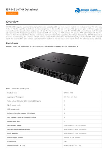
6.Click Discover in the Discover C Series Modules? dialog box if it appears.7.Click Continue.8.Right-click the controller item in the Project Explorer window and select Properties fromthe shortcut menu to display the RT Target Properties dialog box. Select Scan Enginefrom the Category list to display the Scan Engine page.9.Set the Scan Period to 5 ms, then click OK to close the RT Target Properties dialog box.10. Right-click the controller item in the Project Explorer window and select New»NI SoftMotion Axis from the shortcut menu to open the Axis Manager dialog box, shownin Figure 11.11. Click Add New Axis to create an NI SoftMotion axis associated with the NI 9512 module.Axes are automatically bound to an available module. You can double-click the axis nameto rename the axis and give it a descriptive name.Figure 11. Axis Manager Dialog Box12. Click OK to close the Axis Manager dialog box. The new axis is added to the ProjectExplorer window.NoteYou cannot associate more than one axis with the same C Series module.When you have finished these steps your LabVIEW project should look similar to theimage in Figure 12.Getting Started with NI SMD-7620/7621 and NI 9512 Modules National Instruments 15
Figure 12. Project Explorer Window with Modules in Scan Interface ModeStep 4: Configure the NI 9512 AxisThe Axis Configuration dialog box includes configuration options for stepper drive commandsignals, feedback devices, motion and digital I/O, trajectory, and axis setup. Figure 13 shows theparts of the Axis Configuration dialog box for the NI 9512 C Series module. Refer to theNI SoftMotion Module book of the LabVIEW Help for detailed information about eachconfiguration option.Figure 13. Axis Configuration Dialog Box16 ni.com Getting Started with NI SMD-7620/7621 and NI 9512 Modules
Note The Axis Configuration dialog box user interface may not match this imageexactly depending on which version of the LabVIEW NI SoftMotion Module you areusing.Complete the following steps to configure the axis I/O settings for use with theNI SMD-7620/7621 stepper drive.1.Right-click the axis in the Project Explorer window and select Properties from theshortcut menu to open the Axis Configuration dialog box.2.Configure the following settings on the General Settings page ().a.Confirm that Loop Mode is set to Open-Loop. Axes configured in open-loop modeproduce step outputs but do not require feedback from the motor to verify position.b.Set Feedback Source to Encoder 0, if you have connected an encoder, or None if youdo not have an encoder connected.c.Confirm that the Axis Enabled and Enable Drive on Transition to Active Modecheckboxes contain checkmarks. These selections configure the axes to automaticallyactivate when the NI Scan Engine switches to Active mode.Note Disable these options to prevent axes from automatically activating when theNI Scan Engine switches to Active mode.3.If you have connected an encoder, click the Encoder button (Units and Counts Per Unit.) and configure thea.In the Active State section set the Line State for A, B, and Index to High.b.In the Index Reference Criteria section set the Line State for A and B to Inactive.c.Select rev from the Units text box, or type revolutions if you prefer.d.Set the Counts per rev to 8,000. This setting is the encoder resolution in quadraturecounts per revolution and corresponds to the encoder lines per revolution multipliedby four.When you are finished the Encoder Settings page will look similar to Figure 14.Figure 14. Axis Configuration Encoder PageGetting Started with NI SMD-7620/7621 and NI 9512 Modules National Instruments 17
4.Click the Stepper button (a.b.) to open the Stepper page.Ensure that the Stepper Output settings match the following: Output Mode—Step and Direction Output Type—Single-Ended Active State—LowConfigure the Units and Steps Per Unit. Select rev from the Units text box, or type revolutions if you prefer. Set Steps Per revolution to 20,000.The Stepper steps per revolution setting must match the Steps/Rev settingin the NI Stepper Configuration Utility. The NI Stepper Configuration Utility settingsare covered in Step 5: Configure the Drive Using the NI Stepper ConfigurationUtility.Notec.(Optional) Click the Monitor button () and make the following changes toenable NI SoftMotion to disable the drive and turn off the Drive Enable signal whenthe specified position error limit is exceeded.The Monitor button is greyed out if Feedback Source on the Axis Settingspage is set to None.Note5.6.18 Enable the Enforce Position Error Limit checkbox. Set Position Error Limit to a reasonable tolerance for your system, such as 1.Click the Drive Enable button (following: Output Type—Sourcing Active State—Off Safe State—On) and ensure that the Drive Enable settings match theIf you connected the Y1 /Y1- signal, click the Digital I/O button (the following steps to configure the DI 0 signal:) and completea.Double-click the text in the Mapping column and select Drive Fault/Alarm from thedropdown list.b.Ensure that the DI 0 settings match the following: Input Type—Sinking Active State—On Digital Filter—50 µs ni.com Getting Started with NI SMD-7620/7621 and NI 9512 Modules
7.Complete the following additional steps if you do not have limits and home connected atthis time:a.Click the Limits & Home button (b.In the Forward Limit and Reverse Limit sections ensure that the settings match thefollowing:).Note These configuration settings disable limits for initial setup and testingpurposes. National Instruments recommends connecting and enabling limits in yourfinal application.c. Clear the Enable checkbox from both Forward Limit and Reverse Limit. Set the Active State for both Forward Limit and Reverse Limit to Off. Thisprevents a limit warning even though limits are turned off.Open the Home section and clear the Enable checkbox.8.Configure any additional I/O settings according to your system requirements, such asposition compare or position capture signals.9.Click OK to close the Axis Configuration dialog box.10. Right-click the controller item in the Project Explorer window and select Deploy All todeploy the axis information.11. Select File»Save Project to save the project.Step 5: Configure the Drive Using the NI StepperConfiguration Utility1.Launch the NI Stepper Configuration utility.2.Select Drive»Drive Discovery, verify that your host IP address is highlighted, then clickOK.3.When Drive Discovery detects a drive, click Yes in the confirmation dialog box.4.Select the drive you are configuring from the Drive dropdown list.5.Click the I/O button to launch the I/O Configuration dialog box.6.a.Enable the close fault output (Y1) option button to configure the fault signal.b.Enable the When Enable input is (X3) is open option button to configure the driveenable signal.c.(Optional) Configure additional I/O signals on the drive as necessary.Click the Motor button to launch the Motor dialog box.a.Select your motor from the Standard motor dropdown list. If you are using a motorother than one of the standard motors, refer to the NI Stepper Configuration UtilityHelp for information about how to configure it for use with the NI SMD-7620/7621.Getting Started with NI SMD-7620/7621 and NI 9512 Modules National Instruments 19
7.Click the Motion button to launch the Pulse & Direction Control dialog box.8.a.Set Steps/Rev to 20,000.b.(Optional) Set the Step Smoothing Filter and Input Noise Filter as appropriate foryour application. Refer to the NI Stepper Configuration Utility Help for informationabout these settings.Click Download to Drive to apply the updated settings to the drive.Step 6: Enable and Test the Drive Using LabVIEWUse the Interactive Test Panel to test and debug your motion system and configuration settingson the selected axis. With the Interactive Test Panel you can perform a simple straight-line moveand monitor feedback position and position error information, move and I/O status information,change move constraints, get information about software errors and faults, and view position orvelocity plots of the move.Complete the following steps to test your setup after configuring the axis using the AxisConfiguration dialog box.1.Right-click the axis in the Project Explorer window and select Interactive Test Panelfrom the shortcut menu. Opening this dialog box sends the axis settings to the hardware andactivates the I/O on the module.2.On the Move tab set Move Mode to Relative Position and Target Position to 20 rev.3.On the Move Constraints tab set Velocity to 2 rev/sec, Acceleration and Deceleration to20 rev/sec2, and Acceleration Jerk and Deceleration Jerk to 200 rev/sec3. Using theencoder counts per revolution and stepper steps per revolution values specified in thistutorial the motor will move 20 revolutions at 120 rpm.Tip Click the Help button ( ) on the bottom of the dialog box for detailedinformation about the items available in this dialog box.4.Click the
GETTING STARTED NI SMD-7620/7621 Stepper Drives and NI 9512 C Series Modules Note If you are a new user of LabVIEW or ar e unfamiliar with LabVIEW, refer to the Getting Started with LabVIEW manual for information about LabVIEW and LabVIEW terminology. This document explains how to install and c onfigure the NI SMD-7620/7621 stepper drives for