Transcription
Series AM Infrared HeaterInstallation, Operation and Service InstructionsFOR YOUR SAFETYFOR YOUR SAFETYIf you smell gas:1. Open windows2. Don’t touch electrical switches3. Extinguish any open flame4. Immediately call your gas supplierDo not store or use gasoline or otherflammable vapors and liquids in thevicinity of this or any other appliance.CONSIGNES DE SECURITECONSIGNES DE SECURITESi vous sentez une odeur de gaz:1. Ouvrez les fenetres2. Ne touchez pas aux interupteurselectriques3. Eteignez tout flamme nue4. Contactez immediatment votrefournisseur de gazIl est interdit d‘utiliser des liquidesinflammables ou degageant des vapeursinflammables, a proximites de tout appareilfonctionnent au gaz.InstallerRead and thoroughly understand these Instructions before attempting any installation.OwnerRetain this Manual for reference.WARNINGImproper installation, adjustment, alteration, service or maintenance can cause injury, death or propertydamage. Read the installation, operation and service instructions thoroughly before installing or servicingthis equipment.563 Barton Street, Stoney Creek, Ontario L8E 5S1www.superiorradiant.comSeries AMPage 1Feb18,2015 LT173
CAUTION: FIRE OR EXPLOSION HAZARDMaintain clearance to combustible constructions as further specified in this manual. Failureto do so could result in a serious fire hazard. Heaters should not be located in hazardousatmospheres containing flammable vapors or combustible dusts. Signs should be provided instorage areas specifying maximum safe stacking height.CAUTION: MECHANICAL HAZARDThis equipment expands and contracts with each operating cycle. The gas connection,suspension hardware and the installation itself must safely allow this movement. Failure todo so could result in serious fire or explosion hazard.CAUTION: FIRE OR EXPLOSION HAZARDThis heater is equipped with an automatic ignition device. Do not attempt to light the burnerby hand. Failure to comply could result in a serious fire and personal injury hazard.CAUTION: MECHANICAL HAZARDDo not use high pressure (above 1/2 psi) to test the gas supply system with the burnersconnected. Failure to do so could result in damage to the burner and its control componentsrequiring replacement.CAUTION: SERVICE LIFE RISKDo not install equipment in atmospheres containing halogenated hydrocarbons or othercorrosive chemicals. Failure to do so may lead to premature equipment failure andinvalidation of the warranty. Additionally, it is recommended that the equipment be installedwith a slope downward and away from the burner of ¼" in 10' to allow start-up condensatedrainage.Series AMPage 2Feb18,2015
Table of ContentINTRODUCTION. 4INSTALLATION CODES . 4General Installation and Gas Codes . 4Aircraft Hangar Installation . 4Public Garage Installation. 4Parking Structures. 4Gas Supply Lines . 5Electrical . 5Venting . 5GENERAL SPECIFICATIONS . 6GAS SUPPLY . 6Inlet Pressure . 6Manifold Pressure . 6Inlet Connection . 6ELECTRIC SUPPLY . 6FLUE AND OUTSIDE AIR CONNECTION . 6DIMENSIONAL CHARTS . 7CONFIGURATIONS. 8CLEARANCE TO COMBUSTIBLES . 10INSTALLATION. 12INSTALLATION SEQUENCE . 12VENTING / COMBUSTION AIR DUCTING . 26GENERAL REQUIREMENTS . 26UN-VENTED OPERATION . 26VENTED OPERATION . 27Horizontal Venting . 27Vertical Venting . 27Common Vertical Venting . 27Common Horizontal Venting. 28COMBUSTION AIR SUPPLY (OPTIONAL) . 29OUTDOOR INSTALLATION . 30GAS PIPING . 31GENERAL REQUIREMENTS . 31ELECTRICAL WIRING . 32GENERAL REQUIREMENTS . 32BURNER OPERATION . 35STARTING SEQUENCE OF OPERATION . 35MAINTENANCE . 35TROUBLESHOOTING . 36BLOWER MOTOR FAILS TO RUN . 36NO GAS SUPPLY . 36BURNER DOES NOT LIGHT. 36BURNER DOES NOT STAY LIT . 36TROUBLESHOOTING CHART . 37REPLACEMENT PARTS . 38WARRANTY . 39Series AMPage 3Feb18,2015
IntroductionSuperior Radiant Products is a company in the infrared heating industry founded on the principles ofproduct quality and customer commitment.Quality commitments are evidenced by superior design, a regard for design detail and an upgrade ofmaterials wherever justifiable.Customer commitment is apparent through our ready responses to market demands and a never endingtraining and service support program for and through our distributor network.Superior Radiant offers its 18 years of infrared expertise in a cost effective unitary heater design asculmination of that commitment. Series AM models are field assembled, low intensity infrared heatersthat are easy to install and maintain, and which were engineered with significant input from ourcustomers. They are designed to provide economical operation and trouble-free service for years to come.ImportantThese instructions, the layout drawing, local codes and ordinances, and applicable standards such asapply to gas piping and electrical wiring comprise the basic information needed to complete theinstallation, and must be thoroughly understood along with general building codes before proceeding.Only personnel who have been trained and understand all applicable codes should undertake theinstallation. SRP Representatives are Factory Certified in the service and application of thisequipment and can be called on for helpful suggestions about installation.Installation CodesInstallations must comply with local building codes, or in their absence, the latest edition of the nationalregulations and procedures as listed below.General Installation and Gas CodesHeaters must be installed only for use with the type of gas appearing on the rating plate, and theinstallation must conform to the National Fuel Gas Code, ANSI Z223.1/NFPA 54 in the US andCAN/CGA B149.1 and B149.2 Installation Codes in Canada.This heater maybe approved for either indoor or outdoor installation. Not for use in residential dwellings,refer to Rating plate.Aircraft Hangar InstallationInstallation in aircraft hangars must conform to the Standard for Aircraft Hangars, ANSI/NFPA 409 in theUS and CAN/CGA B149.1 and B149.2 Installation Codes in Canada.Public Garage InstallationInstallation in public garages must conform to the Standard for Parking Structures, NFPA-88A orStandard for Repair Garages, NFPA 88B, in the US and CAN/CGA B149.1 and B149.2 InstallationCodes in Canada.Parking StructuresTechnical requirements are outlined in ANSI/NFPA 88B (USA)Series AMPage 4Feb18,2015
IntroductionGas Supply LinesGas supply pipe sizing must be in accordance with the National Fuel Gas Code, ANSI Z223.1/NFPA 54in the US and CAN/CGA B149.1 and B149.2 Installation Codes in Canada.A 1/8" NPT plugged tap must be installed in the gas line connection immediately upstream of the burnerfarthest from the gas supply meter to allow checking of system gas pressure.ElectricalAll heaters must be electrically grounded in accordance with the National Electric Code, ANSI/NFPA 70in the US, and the Canadian Electric Code, CSA C22.1 in Canada, and must comply with all localrequirements.VentingRefer to the National Fuel Gas Code, ANSI Z223.1/NFPA 54 in the US and CAN/CGA B149.1 andB149.2 Installation Codes in Canada for proper location, sizing and installation of vents as well asinformation on clearance requirements when penetrating combustible walls for venting purposes.Series AMPage 5Feb18,2015
General SpecificationsGeneral SpecificationsGas SupplyInlet PressureNatural Gas:MinimumMaximum5.3" W.C.14.0" W.C.Propane Gas:MinimumMaximum11.8" W.C.14.0" W.C.Natural Gas:Propane Gas:AM - 803.65" W.C.10.00" W.C.AM - 1154.05" W.C.10.70" W.C.AM - 1504.05" W.C.10.80" W.C.AM - 2004.30" W.C.10.10" W.C.Manifold PressureInlet ConnectionNatural Gas or Propane: 1/2" female NPTElectric Supply120 VAC, 60 HZ, 1.2 Amp: 84" cord with grounded 3 prong plugFlue and Outside Air Connection4" O.D. male connection for flue adapter and outside air (optional) provided at the heaterSeries AMPage 6Feb18,2015
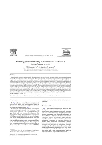
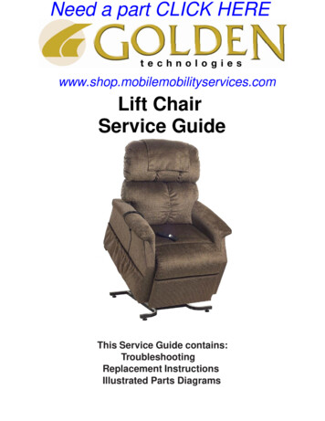
Dimensional Charts10'18"6"16"24"36"15.13"10.25"15.00"12"12"10' - 4"Figure 1: Overall Dimensional InformationELBOW16"BAFFLE SECTIONWHEN INSTALLING, ORIENTBAND CLAMP LOCK BOLTSTO TOP, AT 10 O'CLOCKOR 2 O'CLOCK POSITION3'-6" OR 6' OR 7'-6"COUPLINGREFLECTOR12"10' - 4"18"TUBE24"10'U-TUBEFigure 2: Component Dimensional InformationSeries AMPage 7Feb18,2015
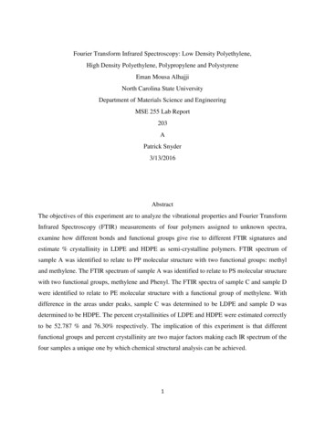
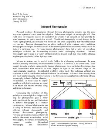
ConfigurationsRate(BTU/Hr)ModelHeat Exchanger Length(ft.)MinimumMaximumBaffleLength (ft.)BaffleKit P/NAM - 8048,000 - 80,00020'30'12’CT047AM - 115AM - 15069,000 - 115,00030'40'12'CT04790,000 - 150,00040'50'CT047AM - 200115,000 - 200,00050'60'12'8’ 4’ (seefig.4 below)CT095Table 1: Configuration InformationNote:- Baffles are always placed in the last section of radiant tube, unless stated / shown otherwise.- Baffles are either aluminized or stainless steel sections 4', 6' and 8' long.- When 12' is required the 6' aluminized steel baffle is lengthened forward (toward the burner) witha 6' stainless steel section.Part numbers for reference are:- CT007Baffle 6' long, aluminized steel- CT006Baffle extension, 6' long stainless steel.- CT026Baffle 4' long, aluminized steel- CT027Baffle 8' long, aluminized steelThe following special configurations are also approved:80,000 BTU/Hr40' heat exchanger with NO baffle80,000 BTU/Hr40' heat exchanger with 6' aluminized baffle in 3rd tube115,000 BTU/Hr40' with 12' baffle in the 3 rd tube & 6' aluminized baffle in the 4th tube (Figure 3).115,000 BTU/Hr50' with 12’ baffle in the 5th tube150,000 BTU/Hr60' heat exchanger with 6’ baffle150,000 BTU/Hr60' heat exchanger with 12’ baffle200,000 BTU/Hr70' heat exchanger with no baffle, a 4' baffle or a 8’ baffle in 7th tube200,000 BTU/Hr70' heat exchanger with 8’baffles in 6th and 7th tubes eachBAFFLE LOCATION FOR 115,000 BTU/Hr, 40 ft. UNITS ONLYStainlesssteel BaffleP/N CT006Twist locktwo 6' bafflesAluminizedBaffleP/N CT0076'20'6'12'Fold taboverAluminizedBaffleP/N CT0076'Fold tabover30'40'Figure 3: Baffle Location AM - 115 Models onlySeries AMPage 8Feb18,2015
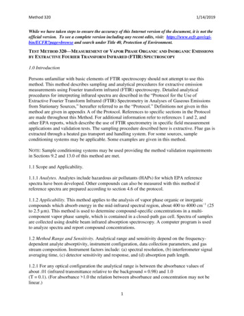
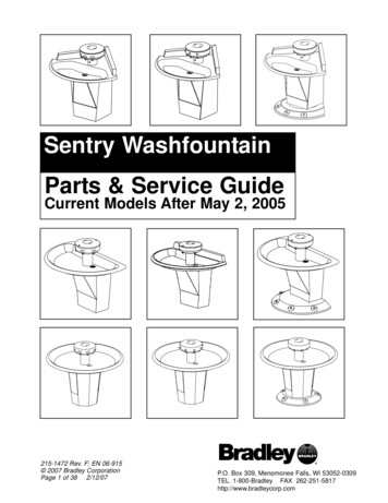
ConfigurationsSpecial configurations continued:BAFFLE LOCATION FOR ALL 200,000 BTU/Hr, 50 ft. UNITS ONLYAluminizedBaffleP/N CT02730'7'-6"AluminizedBaffleP/N CT026Fold tabover3'-6"Fold tabover40'50'BAFFLE LOCATION FOR ALL 200,000 BTU/Hr, 60 ft. UNITS ONLYAluminizedBaffleP/N CT02740'7'-6"AluminizedBaffleP/N CT026Fold tabover3'-6"Fold tabover50'60'Figure 4: Baffle Location AM - 200 Models only.Series AMPage 9Feb18,2015
Clearance to CombustiblesA general clearance of 18” (0.5 m) in every direction is recommended for servicing around eachBurner, if possible.In addition to this it is very important to observe the minimum clearance to combustibles at alltimes to avoid any possibility of property damage or personal injury.WARNING Clearances as marked on the heater body must be maintained from vehicles parked beneath. Signsshould be posted identifying any possible violation of the clearance distances from the heater in allvehicle areas. Maximum allowable stacking height in storage areas should be identified with signs or appropriatemarkings adjacent to the thermostat or in a conspicuous location.Table 2 lists the minimum clearance to combustible materials for various installation configurations. Notethat standard clearances also apply to installation above T-bar ceilings and above decorative grills.Additional clearance may be required for glass, painted surfaces and other materials which maybedamaged by radiant or convective heat.Combustible materials are considered to be wood, compressed paper, plant fibres, plastics, Plexiglas orother materials capable of being ignited and burned. Such materials shall be considered combustibleeven though flame-proofed, fire-retardant treated or plastered.Elbows and U-bends are un-heat treated aluminized material and are typically installed without reflectors.Reflector miter kits are available for U-bends and elbows. Clearance around un-reflectored fittings is 18”,unless a reflector kit is used, refer to table 2.Adequate clearance to sprinkler heads must be maintained.The stated clearance to combustibles represents a surface temperature of 90 F (50 C) above roomtemperature. Building materials with low heat tolerance (such as plastics, vinyl siding, canvas, tri-ply,etc ) maybe subject to degradation at lower temperatures. It is the installer’s responsibility to assurethat adjacent materials are protected from degradation.Note 1:Bottom Shields are approved for all burner sizes. The “below” clearance (dimension C in Table 2)may be reduced by 25% when an approved Bottom Shield is used.Note 2:Reduced clearances downstream from the burner are approved for all configurations. Dimensions “B”,“C”, and “D” in Table 2 can be reduced for locations 25' (7.6 m) or more downstream from a burner,maximum reduction is 50%Series AMPage 10Feb18,2015
Clearance to CombustiblesTable 2: Minimum Clearance to CombustiblesModel No.: AMReflector 32"18"18"32"18"HorizontalABDC45 Reflector TiltABDCOne Side ExtensionADBCTwo Side ExtensionABCDU-Tube, HorizontalABDCU-Tube, Opposite 45 ABDVentedSeries AMPage 11Feb18,2015
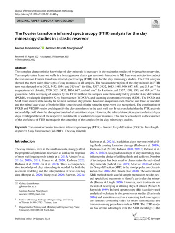
InstallationInstallation SequenceGenerally, there is no unique sequence for installation of the burner or heat exchanger. A review of thejob site will usually indicate a logical installation order. However, time and expense can be saved ifinstallation is begun at the most critical dimension, watching for interference from overhead doors,cranes, auto lifts etc. Figure 5 provides a general overview of the components utilized in the installation,as well as their general relationship.End CapReflector OverlapApprox. 8"LooseScrewsFasten Endcapwith ScrewsTightScrewsVentAdapterLooseScrewsBend Tabover Endof TubeTightScrews**Install Baffle(s) as requiredin the last section of tube oras specified in this manualClose all chain links"S" hooks, "J" boltsand turnbuckles orany open connection.Install "J" Boltat first hangerHeat ube & ReflectorHangersBurnerAssembly3"GasketFigure 5: General Overview of InstallationA general ordered sequence for installation is provided below for reference.HANGERS INSTALLATION Suspension mechanism must allow for lateral tubing expansion. A minimum 12" length weldedlink chain with a working load limit of at least 200 lbs. is recommended (refer to Figure 6 formore details). SRP recommends and make available “quick links” for connecting chain. Ifany open ended “S” hooks and turnbuckles are used, the open ends must be closed to avoidunhooking chain with inadvertent contact. Locate hanging chain at predetermined suspension points in the structure. It is required that thefirst 2 hangers be about 8' to 9' away. Thereafter, 10' apart on average is acceptable for theremainder of the heat exchanger. At no time should hangers be more than 12' apart, (see Figure 7).Series AMPage 12Feb18,2015
InstallationTrussI-BeamConcrete BeamI-BeamEye Bolt12"Min.AnchorBeam Clamp24"Min.Note:Close all "S" hooks,chain links, "J" boltsand turnbuckles orany open connection.3/8"ThreadedRod12"Min.TurnbuckleChain linkFigure 6: Suspension Mechanism Install the tube and reflector support hanger on the chain with “S-hooks” refer to Figure 6 &Figure 7.VentingSide"Last Hanger"10'10'Close all open ended"S" hooks, chain linksand turnbuckles or anyopen connection.8' to 9'BurnerSide"First Hanger"Figure 7: Hanging Points Place the first (flanged, aluminized) tube in the first two hangers (Figure 8). Be sure the flange istoward the intended burner location. The other end of the tube should have the first couplingalready loosely fitted.Series AMPage 13Feb18,2015
InstallationTUBE INSTALLATION Always use all the hangers supplied. As a rule the combustion tube (first tube) utilizes 2 hangersand thereafter 1 hanger per 10' section. It is required that the first hanging point be 2" to 8"from the burner mounting flange, and tube weld seam must face down, refer to Figure 8 formore details.10'Locate Tube andReflector Hangersevery 10' thereafter.10'8' - 9'Coupling Should BeLoosely FittedInstall "J" Boltat first hangerTubeFlangeCombustionTubeTube WeldSeam FacingDownClose all open ended"S" hooks, chain links,and turnbuckles or anyopen connection.Tube & ReflectorHangers2"-8"Figure 8: Installation of First section of Flanged Tube For all remaining tubes, fit the end of the tube with a coupling refer to Figure 9, (the couplingshould be loose).Close all open ended"S" hooks, chain links,and turnbuckles or anyopen connection.10'Coupling(loosely fitted)HeatexchangertubeTube weldseam facingdownFigure 9: Installation of Heat Exchanger Tube and CouplingSeries AMPage 14Feb18,2015
Installation Tighten the cradle loops of the first hanger with the “J-Bolt” found in the burner box, to snuglyhold the combustion tube from rotating see Figure 10.Note: For all coupling joints, ensure that the tube joint is in the center of the couplinglength, and that the overlap joint of the coupling is above the centerline of the tube. Alsoensure that the weld seam on ALL tubes is facing down.Note: In order to obtain smoothly sealed coupling liners, tighten each of the couplingbands progressively and alternately. Tightening one band completely before the other mayresult in an undesirable wrinkle in the liner (refer to Figure 10). Be sure not to overtorque the coupling. (Torque coupling to 15-25 lbf-ft).Place Tube in theReflector Hangeras shown.Tube weldseamReflector HangerInstall "J" Bolt at theFirst Hanger Only.TubeweldseamWhen Installing, OrientBand Clamp Lock Boltsto Top, at 10 o'clockOr 2 o'clock Position toAvoid Contact with theReflector.Torque to 15-25 ft.-lbsInstallation of Tube CouplingInstallation of Reflector Hangersand "J" BoltNote:Close all open ended "S" hooks, chain links,and turnbuckles or any open connection.Figure 10: “J” Bolt and Coupling Installations Continue placing tubes, couplings and reflectors to complete the heater assembly. Ensure heatexchanger sections line up straight. Couplings should be tightened as heat exchanger is placed,since it is more difficult to do so once the reflector is in position.Series AMPage 15Feb18,2015
InstallationHEATER AND BAFFLE INSTALLATION Locate the burner gasket provided, bolt the burner in place on the tube flange with providedhardware. Burner must never be installed in a tilted position. The sense electrode of the burnercup should be in the 12 o’clock position (Figure 11).TubeFlangeNote:Burner MUST NEVERbe tilted sideways.Only install as shown.BurnerAssemblyGasketNote:Close all open ended "S" hooks, chain links,and turnbuckles or any open connection.Figure 11: Burner Gasket Installation If required for your heater model (refer to Table 1), install the baffle at the end of the heatexchanger. The small tab on the baffle is folded over the end of the tube and clamped in place bythe vent connector and vent system, refer to Figure 12.Note: Baffles are always placed at the end of the last heat exchanger tube length, with theexception of the special configurations (115,000 BTUH with a 40' tube length, and 200,000BTUH with 50' and 60' tube length) refer to Figure 3 and Figure 4 for more details.Note: Baffles are either one or two sections (each section is 6' in length). Multiple sections aresimply clipped together. Where stainless and aluminized sections are supplied, alwaysplace the stainless steel section closest to the burner. The easiest installation method is topull the baffle through the tube using a long wire.Install Baffleas required inlast sectionof tubeVentAdapterBend Tabover Endof Tubeat 6 O'clockpositionNote:Close all open ended "S" hooks, chain links,and turnbuckles or any open connection.Figure 12: Baffle InstallationSeries AMPage 16Feb18,2015
Installation A general overall view of the tubes and reflector hangers are shown in Figure 13 belowVentAdapterLocate Tube andReflector Hangersevery 10' thereafter.*Note: (30' system shownhere, the same principleshould be followed for 40', 50'systems or more)Refer to Installation Sequencefor more details.10' TubeBend Tabover Endof Tube10' Tube10' FlangedTube**Install Baffle(s)as required in thelast section of tubeor as specified in thismanual8' - 9'Install "J" Boltat first hangerHeat ExchangerTubeTubeFlangeTubeCouplingNote:Close all chain links "S" hooks, "J" boltsand turnbuckles or any open connection.CombustionTubeTube & ReflectorHangersBurnerAssembly2"to8"GasketFigure 13: Overall view of Tubes and Reflector HangersSeries AMPage 17Feb18,2015
InstallationREFLECTOR INSTALLATION Slide a reflector section into place within the support hanger, (Figure 14).Slide Reflector throughthe Hanger and ReflectorSupport as shown.Note:Close all chain links "S" hooks,"J" bolts and turnbuckles or anyopen connection.Figure 14: Reflector Installation Install reflector support brackets, one at each reflector overlap position, and one in the middle ofeach 10' reflector length. Figure 15 shows the installation of the reflector support bracket.TubeSpring ClipReflector Bracket1. Place Reflector Bracketunderneath the tube.2. Hook the Spring Clip withthe Reflector Bracket and rotateover the tube.3. Push down the Spring Clipand slide underneath theReflector Bracket.Reflector BracketFigure 15: Reflector Support Bracket InstallationSeries AMPage 18Feb18,2015
InstallationNote: Reflectors should overlap adjacent reflectors 4" to 6". Be sure not to tile reflector sections;that is, reflector sections must be either above both adjacent reflector sections, or below bothadjacent reflector sections. Refer to Figure 16.VentTerminationEndReflectorSupportReflector OverlapApprox. 6"LooseScrewsFasten Endcapwith ScrewsTightScrewsLooseScrewsTightScrewsHeater EndFigure 16: Reflector Overlap IllustrationSeries AMPage 19Feb18,2015
Installation Secure every second reflector overlap together with a minimum of 2 - #8 x 3/8" inch long screws(not supplied), and secure reflector to the reflector bracket at this point by tightening down #8 x1¼" screws supplied with reflector brackets (Figure 17). The remaining reflector overlap jointsand reflector brackets are left loose to accommodate system movement.Secure reflector to reflectorbracket by TIGHTENING#8 x 1 1/4" long screws everyother overlap on each side.Secure every SECOND reflectoroverlap with a minimum of 2#8 x 3/8" long screwson each sideLOOSE screwsNote:Close all chain links "S" hooks, "J" boltsand turnbuckles or any open connection.Figure 17: Reflector Supports Installation and Reflector Overlap Install End Cap as shown in Figure 5 and Figure 18.Insert End Cap into Reflectorand Secure it with #8 x 3/8" ScrewsNote:Close all chain links "S" hooks, "
Series AM Infrared Heater Installation, Operation and Service Instructions Installer Read and thoroughly understand these Instructions before attempting any installation. . - Baffles are always placed in the last section of radiant tube, unless stated / shown otherwise. - Baffles are either aluminized or stainless steel sections 4', 6' and 8 .