Transcription
Sentry WashfountainParts & Service GuideCurrent Models After May 2, 2005215-1472 Rev. F; EN 06-915 2007 Bradley CorporationPage 1 of 38 2/12/07P.O. Box 309, Menomonee Falls, WI 53052-0309TEL. 1-800-Bradley FAX 262-251-5817http://www.bradleycorp.com
Sentry WashfountainParts and Service GuideTable of ContentsWashfountain IdentificationPage #Identification Charts and Model Numbers . . . . . . . . . . . . . . . . . . . . . . . . . . . . . . . . . . . . . . . . . . . . . .3How to Determine Drain Type . . . . . . . . . . . . . . . . . . . . . . . . . . . . . . . . . . . . . . . . . . . . . . . . . . . . . . .4Sentry WashfountainsInfrared (IR) — Sprayhead Assembly . . . . . . . . . . . . . . . . . . . . . . . . . . . . . . . . . . . . . . . . . . . . . . . . . .5Infrared (IR) Part 1 — Solenoid Valve Assembly (24V transformer) . . . . . . . . . . . . . . . . . . . . . . . .6-9Infrared (IR) Part 2 — Solenoid Valve Components (24V transformer) . . . . . . . . . . . . . . . . . . . . . .10Infrared (IR) — Sensor and Solenoid Valve Troubleshooting . . . . . . . . . . . . . . . . . . . . . . . . . . . . . .11Infrared (IR) SN2003, SN2023, SN2013, SN2033 Wiring Diagram . . . . . . . . . . . . . . . . . . . . . . . . .12Infrared (IR) SN2004, SN2024 Wiring Diagram . . . . . . . . . . . . . . . . . . . . . . . . . . . . . . . . . . . . . . . .13Infrared (IR) SN2005 Wiring Diagram . . . . . . . . . . . . . . . . . . . . . . . . . . . . . . . . . . . . . . . . . . . . . . . .14Infrared (IR) SN2008 Wiring Diagram . . . . . . . . . . . . . . . . . . . . . . . . . . . . . . . . . . . . . . . . . . . . . . . .15Sentry Transformers . . . . . . . . . . . . . . . . . . . . . . . . . . . . . . . . . . . . . . . . . . . . . . . . . . . . . . . . . . . . . . .16Supply Valves — Pressure Balancing Complete Assembly . . . . . . . . . . . . . . . . . . . . . . . . . . . . . . . .17Air Metering Valve (AST4) — Hand Pushbutton and Sprayhead . . . . . . . . . . . . . . . . . . . . . . . . . . .18Air Metering Valve (AST4-F) — Foot Pushbutton and Actuator . . . . . . . . . . . . . . . . . . . . . . . . . . . .19Air Metering Valve (AST4) Part 1 — Assembly and Components . . . . . . . . . . . . . . . . . . . . . . . .20-23Air Metering Valve (AST4) Part 1 — Assembly and Components . . . . . . . . . . . . . . . . . . . . . . . .20-23Air Metering Valve (AST4) Part — Adjustment . . . . . . . . . . . . . . . . . . . . . . . . . . . . . . . . . . . . . . . . .24Air Metering Valve (AST4) Part 2 — Assembly and Components . . . . . . . . . . . . . . . . . . . . . . . . . .25Troubleshooting Air Valve Metering Hand Control (AST4) . . . . . . . . . . . . . . . . . . . . . . . . . . . . .26-28Vernatherm Thermostatic Mixing Valve Troubleshooting . . . . . . . . . . . . . . . . . . . . . . . . . . . . . . . . .29Vernatherm Mixing Valve — TMA . . . . . . . . . . . . . . . . . . . . . . . . . . . . . . . . . . . . . . . . . . . . . . . . .30Cleaning the Strainer . . . . . . . . . . . . . . . . . . . . . . . . . . . . . . . . . . . . . . . . . . . . . . . . . . . . . . . . . . .29-30Control Valve Illustrations . . . . . . . . . . . . . . . . . . . . . . . . . . . . . . . . . . . . . . . . . . . . . . . . . . . . . . . . . .31Check Valve Troubleshooting Instructions . . . . . . . . . . . . . . . . . . . . . . . . . . . . . . . . . . . . . . . . . . . . .32Care and Cleaning of Stainless Steel Sentry Washfountains . . . . . . . . . . . . . . . . . . . . . . . . . . . . . . .32Sprayhead Cover and Soap System . . . . . . . . . . . . . . . . . . . . . . . . . . . . . . . . . . . . . . . . . . . . . . . .33-34Pedestal Assembly — Access Panels, Bowl Hardware, Drain Parts . . . . . . . . . . . . . . . . . . . . . . . . .35Backsplash Retrofit Kits — S65-237 for 36" Semi, S65-238 for 54" Semi . . . . . . . . . . . . . . . . . . . .36Shroud/Towel Dispenser — Installed on a Shroud . . . . . . . . . . . . . . . . . . . . . . . . . . . . . . . . . . . . . .37Towel Dispenser — Installed on a Pipe . . . . . . . . . . . . . . . . . . . . . . . . . . . . . . . . . . . . . . . . . . . . . . .3822/12/07Bradley Corporation 215-1472 Rev. F; EN 06-915
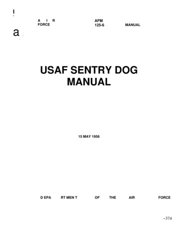
Sentry WashfountainParts and Service GuideSentry Washfountain ProductsStainless Steel– Infrared, Hand or Foot Operated SN2004/IRReliable Pushbutton Activated Air Metering orInfrared ControlAvailable in a 54" or 36" Bowl SizeStandard Height 54" Model with Hand or InfraredControl is ADA CompliantFactory Tested and Shipped PreassembledVandal Resistant and Easy to CleanModels ST-FSemi-Circular – Floor-MountedSemi-Circular – Floor-MountedSemi-Circular – Wall-MountedSemi-Circular – Wall-MountedCircular – Floor-MountedCircular – Floor-MountedCorner – Floor-MountedCorner – -FSN2013/AST-FSN2013/ASTSN2033/IRBradley Corporation 215-1472 Rev. F; EN 06-9152/12/073
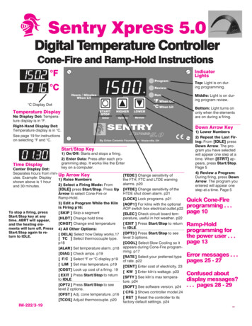
Sentry WashfountainParts and Service GuideHow to Determine Drain Type(Parts may vary depending upon drain type.Identify your drain type before continuing.)TYPE A:SUPPLIES BELOW,VENT OFF DRAIN.P-TRAP FURNISHED BY OTHERS.TYPE H:SUPPLIES BELOW,CENTRALLY-RISING VENT.P-TRAP FURNISHED.42/12/07TYPE B:SUPPLIES ABOVE,CENTRALLY-RISING VENT.P-TRAP FURNISHED.TYPE O:SUPPLIES ABOVE,VENT OFF DRAIN.P-TRAP FURNISHED BY OTHERS.Bradley Corporation 215-1472 Rev. F; EN 06-915
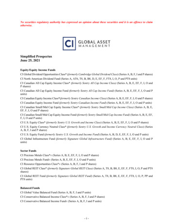
Sentry WashfountainParts and Service GuideInfrared (IR) — Sprayhead Assembly121276834591110Parts List — Infrared Sensor and ModuleItemPart No.Description54" CornerQty36" SemiQty54" SemiQty36" CircleQty54" CircleQty1—Shell111112269-982Lens (window)334583160-245Screw 10-24 x 1/2"66810164142-002BTLock Washer66810165142-002AVFlat washer66810166269-1184Sensor334587182-100Lens Support (Rubber Block)334588159-363Sensor Mounting Bracket334589161-082Nut - Extension 1/4"-20 x 5-1/8"2222210269-621Terminal - female disconnect9912152411S05-157Aerator Assembly (Std 0.5 GPM)3345812110-115Nut - 1/2" - 1433458Parts List — Aerator AssemblyItem123*4*Part No. DescriptionS05-142A153-402A145-090130-141Std. Aerator, 0.5 GPMAdapter90 Connector 1/4" tube x 1/8" NPTSpanner Wrench for AeratorS05-157Qty4111—321Spanner wrench not included in AssembliesBradley Corporation 215-1472 Rev. F; EN 06-9152/12/075
Sentry WashfountainParts and Service GuideInfrared (IR) Part 1 — Solenoid Valve Assembly (24V Transformer)1161213543910721481Parts List — Solenoid Valve Assembly54" CornerItem*6Part No.Description36" SemiQty1S27-102STOP/CHECK VALVE222269-1735FLEX HOSE223140-928BRACKET114269-625TERMINAL BLOCK115P18-054SCREW #10-24 X 3/8226160-447SCREW #8-16 X 5/8337S01-524THERMOSTATIC MIXING VALVE118S39-685ADAPTER (OPTIONAL SINGLE TEMPERED LINE)119S07-067SOLENOID VALVE - CLOSED BODY (BLACK)1110S07-067ASOLENOID VALVE -THRU BODY (GRAY)2211R68-600011-BTUBING 1/4 OD BLACK**12R68-600011-GTUBING 1/4 OD GREEN**13R68-600011-RTUBING 1/4 OD RED**14S45-2146VALVE ASSY TMA 36S & 54K11Specify length in feet.2/12/07Bradley Corporation 215-1472 Rev. F; EN 06-915
Sentry WashfountainParts and Service GuideInfrared (IR) Part 1 — Solenoid Valve Assembly (24V Transformer)111213144651539107218Parts List — Solenoid Valve Assembly — 54" SemiItem*Part No.DescriptionQty1S27-102STOP/CHECK VALVE22269-1735FLEX HOSE23140-928BRACKET14269-647TERMINAL BLOCK15P18-054SCREW #10-24 X 3/826160-447SCREW #8-16 X 5/847S01-524THERMOSTATIC MIXING VALVE18S39-685ADAPTER (OPTIONAL SINGLE TEMPERED LINE)19S07-067SOLENOID VALVE - CLOSED BODY (BLACK)110S07-067ASOLENOID VALVE-THRU BODY (GRAY)311R68-600011-YTUBING 1/4 OD YELLOW*12R68-600011-BTUBING 1/4 OD BLACK*13R68-600011-GTUBING 1/4 OD GREEN*14R68-600011-RTUBING 1/4 OD RED*15S45-2148VALVE ASSY TMA 54S1Specify length in feet.Bradley Corporation 215-1472 Rev. F; EN 06-9152/12/077
Sentry WashfountainParts and Service GuideInfrared (IR) Part 1 — Solenoid Valve Assembly (24V Transformer)11121314154653910721618Parts List — Solenoid Valve Assembly — 36" CircleItem*8Part No.DescriptionQty1S27-102STOP/CHECK VALVE22269-1735FLEX HOSE23140-940BRACKET14269-625TERMINAL BLOCK25P18-054SCREW #10-24 X 3/826160-447SCREW #8-16 X 5/857S01-524THERMOSTATIC MIXING VALVE18S39-685ADAPTER (OPTIONAL SINGLE TEMPERED LINE)19S07-067SOLENOID VALVE - CLOSED BODY (BLACK)110S07-067ASOLENOID VALVE - THRU BODY (GRAY)411R68-600011-YTUBING 1/4 OD YELLOW*12R68-600011-BTUBING 1/4 OD BLACK*13R68-600011-GTUBING 1/4 OD GREEN*14R68-600011-RTUBING 1/4 OD RED*15R68-600011TUBING 1/4 OD CLEAR*16S45-2150VALVE ASSY TMA/IR 36C1Specify length in feet.2/12/07Bradley Corporation 215-1472 Rev. F; EN 06-915
Sentry WashfountainParts and Service GuideInfrared (IR) Part 1 — Solenoid Valve Assembly (24V Transformer)11121314111213144659310271581Parts List — Solenoid Valve Assembly — 54" CircleItem*Part No.DescriptionQty1S27-102STOP/CHECK VALVE22269-1735FLEX HOSE23140-941BRACKET14269-647TERMINAL BLOCK25P18-054SCREW #10-24 X 3/826160-447SCREW #8-16 X 5/887S01-524THERMOSTATIC MIXING VALVE18S39-685ADAPTER (OPTIONAL SINGLE TEMPERED LINE)19S07-067SOLENOID VALVE - CLOSED BODY (BLACK)110S07-067ASOLENOID VALVE -THRU BODY (GRAY)711R68-600011-YTUBING 1/4 OD YELLOW*12R68-600011-BTUBING 1/4 OD BLACK*13R68-600011-GTUBING 1/4 OD GREEN*14R68-600011-RTUBING 1/4 OD RED*15S45-2152VALVE ASSY TMA/IR 54C1Specify length in feet.Bradley Corporation 215-1472 Rev. F; EN 06-9152/12/079
Sentry WashfountainParts and Service GuideInfrared (IR) Part 2 — Solenoid Valve Assembly (24V Transformer)124OR356712OR 13891011Parts List — Solenoid Valve AssemblyItem10Part No.DescriptionQty1110-231NUT 1/4 TUBE12118-307VALVE BODY 1/4" CLOSED13118-307AVALVE BODY 1/4" TURE17269-578SPRING18269-1729ARMATURE HOUSING19269-1730CLAMP110160-447SCREW #8-16 X 5/8311269-579COIL, SOLENOID VALVE112S07-067SOLENOID VALVE CLOSED BODY113S07-067ASOLENOID VALVE THRU BODY12/12/07Bradley Corporation 215-1472 Rev. F; EN 06-915
Parts and Service GuideSentry WashfountainInfrared (IR) — Sensor and Solenoid Valve TroubleshootingIf a station is not functioning properly it is most likely either the solenoid valve or the sensor.Troubleshooting multi station units is fairly easy, as you can swap parts (actually just by changing the wires)and use the process of elimination to figure out which of the 2 parts is causing the problem.How the system operates:1. The transformer sends 24 volts to the sensor.2. The sensor acts only as a switch.3. When hands go into the active field of the sensor, the sensor activates and sends a power signalon to the solenoid valve.4. The power signal activates and opens the solenoid valve which allows the water to flow to thesprayhead. The solenoid valve stays open allowing water to flow as long as it is receiving asignal form the sensor (hands remain in the active field).5. When hands are removed from the active field, the sensor turns off (note some models have aslight delay feature built-in.) and shuts off the power signal to the solenoid valve.CAUTION:Problem:Cause:Solution:Turn off water supplies to unit before troubleshooting.An individual operating station fails to shut off and drips.There is debris trapped between the diaphragm and the valve seat.Remove debris between diaphragm and the valve seat.1. Remove the three #8 Phillips-head screws that hold the solenoid valve assembly together. Becareful not to lose the armature or spring.2. Remove the diaphragm. Remove any particles that have been trapped between the diaphragmand the valve seat. Rinse off the diaphragm and inspect for damage. Make sure the center orifice and both small side orifices are open.3. Reassemble in reverse order, being careful not to overtighten the Phillips-head screws or youmay crack the plastic valve body. Tighten until the armature plate makes contact with the plasticbody.4. Reconnect the wiring per the appropriate diagram on next 4 pages.Problem:Cause:Solution:An individual operating station fails to turn on.A failed coil for the valve or loose electrical connection to the terminal.Test the station to determine cause.1. Disconnect the wires from the coil of an adjacent valve. Disconnect the wires from the problemvalve and reconnect to the adjacent valve.2. Turn on electrical and water supplies to the unit. Pass your hand in front of the sensor of theproblem station, and the adjacent station should turn on.If the adjacent station turns on and cycles normally, replace the coil on the problem valve.If the adjacent valve fails to turn on, inspect the wires from the sensor cable and do the following: make sure there are no breaks and that the fully insulated disconnect terminals are firmlycrimped in place; turn off the electrical and water supplies; reconnect to the adjacent valve and turn on the water supplies to the unit; pass your hand in front of the sensor. If the station still fails to turn on, replace the sensor.Bradley Corporation 215-1472 Rev. F; EN 06-9152/12/0711
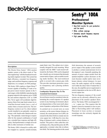
Sentry WashfountainParts and Service GuideInfrared (IR) SN2003, SN2023, SN2013, SN2033 Wiring DiagramBlueSolenoid TubeConnectorCompression NutRedTo sensorsin sprayheadVernatherm TMVSupply InletsBlack24 VAC from transformer– 18 Gauge wires bycustomer to transformerscrew terminals122/12/07Solenoid ValveAssemblyBradley Corporation 215-1472 Rev. F; EN 06-915
Sentry WashfountainParts and Service GuideInfrared (IR) SN2004, SN2024 Wiring DiagramSolenoid ValveAssemblyBlueSolenoid TubeConnectorCompression NutRedTo sensorsin sprayheadVernatherm TMVBlackSupply Inlets24 VAC from transformer– 18 Gauge wires bycustomer to transformerscrew terminalsBradley Corporation 215-1472 Rev. F; EN 06-9152/12/0713
Sentry WashfountainParts and Service GuideInfrared (IR) SN2005 Wiring DiagramSolenoid TubeConnectorCompression NutSolenoid ValveAssembly24 VAC from transformer– 18 Gauge wires bycustomer to transformerscrew terminalsSupply InletsVernatherm TMV142/12/07Bradley Corporation 215-1472 Rev. F; EN 06-915
Sentry WashfountainParts and Service GuideInfrared (IR) SN2008 Wiring DiagramSolenoid TubeConnectorCompression NutSolenoid ValveAssembly24 VAC from transformer– 18 Gauge wires bycustomer to transformerscrew terminalsSupply InletsVernatherm TMVBradley Corporation 215-1472 Rev. F; EN 06-9152/12/0715
Sentry WashfountainParts and Service GuideSentry TransformersModelDescriptionCurrent Part NumberPrior to May 2003QtyQtySN200336" Semi-Circular – Floor MountedS45-20451269-645SN200454" Semi-Circular – Floor MountedS45-20451269-6451SN202336" Semi-Circular – Wall MountedS45-20451269-6451SN202454" Semi-Circular – Wall MountedS45-20451269-6451SN200536" Circular – Floor MountedS45-20452* 269-7031SN200854" Circular – Floor MountedS45-20452* 269-7031SN201354" Corner – Floor MountedS45-20451269-6451SN203354" Corner – Wall MountedS45-20451269-6451*161Available for service.2/12/07Bradley Corporation 215-1472 Rev. F; EN 06-915
Sentry WashfountainParts and Service GuideSupply Valves — Pressure Balancing Complete Assembly1265374PBV —Pressure BalancingComplete Assy. as Shown - S67-516Parts List — Supply Valve S67-516ItemPart No.DescriptionQty1169-168PIPE PLUG12S67-594PBV VALVE13128-032HANDLE FOR VALVE14160-214SCREW FOR HANDLE15113-339NIPPLE – 1/2"16169-639ELBOW27269-1735STAINLESS STEEL FLEX HOSE1Bradley Corporation 215-1472 Rev. F; EN 06-9152/12/0717
Sentry WashfountainParts and Service GuideAir Metering Valve (AST4) — Hand Pushbutton and Sprayhead1112Pushbutton Replacement13IMPORTANT: Turn off watersupplies beforereplacing thepushbutton.141554321091. Remove the sprayhead cover by removingthe two screws holding the cover to thesprayhead module.6202. Inside sprayhead, unscrew the two screwsthat hold the actuator body to the bracketbeing careful of the spring that will release.817773. Unscrew and remove the coupling if necessary.1624. Unscrew and remove the brass nut if necessary. This will allow the pushbutton assembly to be removed.195. Carefully take apart the assembly andreplace the parts as needed.176. After replacement is complete, reassemblethe pushbutton and sprayhead as shown.21Parts List — PushbuttonItemnnnnnnnPart No.DescriptionShell36" SemiQty54" SemiQty36" CircleQty54" CircleQty1—2S08-324Pushbutton Assy. (includes items 3 thru 5)3128-090Pushbutton Only334584179-102Guide for pushbutton334585147-033Screw for pushbutton334586140-743Bracket - Actuator334587110-115Nut 1/2"-14334588169-890Connector 1/8" tube x 10-32 Thd.3345891111133458269-11868"L" Fitting Adjustable334510 118-279Actuator Body3345811Spring3345812 125-099U-Cup for piston3345813 119-227APiston3345814 198-010Duckbill3345815 160-165Screw - Body mounting6681016—135-06516 R68-600008Tubing 1/8" OD (specify length in feet)————Aerator Assembly (Std 0.5 GPM)3345819 161-082Nut - Extension 1/4"-20 x 5-1/8"2222220 130-141Spanner Wrench for Aerators1111121 130-023Spanner Wrench for Pushbuttons11111* 17 S05-157nPrepack S65-168A*See following page for additional information.1854" CornerQty2/12/07Bradley Corporation 215-1472 Rev. F; EN 06-915
Sentry WashfountainParts and Service GuideAir Metering Valve (AST4-F) — Foot Pushbutton and ActuatorParts List — Aerator AssemblyItemPart No. 130-141Std. Aerator, 0.5 GPMAdapter90 Connector 1/4" tube x 1/8" NPTSpanner Wrench for Aerator423111—1Spanner wrench not included in Assemblies1633678285474125Foot Button Assembly S45-1543Actuator Assembly S08-288Parts List — Pushbutton& Actuator Assy.Item1Part No.S08-288Qty1DescriptionParts List — S08-288Actuator Assy.ItemPart No.QtyDescriptionActuator Assy.1160-2764Screw 8-32 x ¾"140-4931Mounting Diaphragm4128-0901Pushbutton4269-6131Back Plate5179-0711Pushbutton Guide5161-0624Nut 8-326110-1151Nut 1/2"-146142-002CR4Washer #8 w for escutcheon8169-8901Fitting - tube connector 10-32 x 1/8"Bradley Corporation 215-1472 Rev. F; EN 06-9152/12/0719
Sentry WashfountainParts and Service GuideAir Metering Valve (AST4) Part 1 — Assembly and Components10121154936821314151671Parts List — Air Metering Valve Assembly54" CornerItem*20Part No.Description36" SemiQty1S27-102STOP/CHECK VALVE222269-1735FLEX HOSE223140-928BRACKET114P18-054SCREW #10-24 X 3/8225160-447SCREW #8-16 X 5/8336S01-524THERMOSTATIC MIXING VALVE117S39-685ADAPTER (OPTIONAL SINGLE TEMPERED LINE)118S07-077AAST4 VALVE, THROUGH BODY (GRAY)229S07-077AST4 VALVE, CLOSED BODY (BLACK)1110R68-600011-BTUBING 1/4 OD BLACK**11R68-600011-GTUBING 1/4 OD GREEN**12R68-600011-RTUBING 1/4 OD RED**13R68-00008-BTUBING 1/8 OD BLACK**14R68-00008-GTUBING 1/8 OD GREEN**15R68-00008-RTUBING 1/8 OD RED**16S08-443TMAVALVE ASSY AST11Specify length in feet.2/12/07Bradley Corporation 215-1472 Rev. F; EN 06-915
Sentry WashfountainParts and Service GuideAir Metering Valve (AST4) Part 1 — Assembly and Components101112135493862171618151471Parts List — Air Metering Valve Assembly — 54" SemiItem*Part No.DescriptionQty1S27-102STOP/CHECK VALVE22269-1735FLEX HOSE23140-928BRACKET14P18-054SCREW #10-24 X 3/825160-447SCREW #8-16 X 5/846S01-524THERMOSTATIC MIXING VALVE17S39-685ADAPTER (OPTIONAL SINGLE TEMPERED LINE)18S07-077AAST4 VALVE, THROUGH BODY (GRAY)39S07-077AST4 VALVE, CLOSED BODY (BLACK)110R68-600011-YTUBING 1/4 OD YELLOW*11R68-600011-BTUBING 1/4 OD BLACK*12R68-600011-GTUBING 1/4 OD GREEN*13R68-600011-RTUBING 1/4 OD RED*14R68-600008-YTUBING 1/8 OD YELLOW*15R68-00008-BTUBING 1/8 OD BLACK*16R68-00008-GTUBING 1/8 OD GREEN*17R68-00008-RTUBING 1/8 OD RED*18S08-444TMAVALVE ASSY AST41Specify length in feet.Bradley Corporation 215-1472 Rev. F; EN 06-9152/12/0721
Sentry WashfountainParts and Service GuideAir Metering Valve (AST4) Part 1 — Assembly and Components1011121314549386192181720161517Parts List — Air Metering Valve Assembly — 36" CircleItem*22Part No.DescriptionQty1S27-102STOP/CHECK VALVE22269-1735FLEX HOSE23140-940BRACKET14P18-054SCREW #10-24 X 3/825160-447SCREW #8-16 X 5/856S01-524THERMOSTATIC MIXING VALVE17S39-685ADAPTER (OPTIONAL SINGLE TEMPERED LINE)18S07-077AAST4VALVE,THROUGH BODY (GRAY)49S07-077AST4 VALVE, CLOSED BODY (BLACK)110R68-600011-YTUBING 1/4 OD YELLOW*11R68-600011-BTUBING 1/4 DD BLACK*12R68-600011-GTUBING 1/4 OD GREEN*13R68-600011-RTUBING 1/4 OD RED*14R68-600011TUBING 1/4 OD CLEAR*15R68-00008-YTUBING 1/8 OD YELLOW*16R68-00008-BTUBING 1/8OD BLACK*17R68-00008-GTUBING 1/8 OD GREEN*18R68-00008-RTUBING 1/8 OD RED*19R68-00008TUBING 1/8 OD CLEAR*20S08-445TMAVALVE ASSY, AST1Specify length in feet.2/12/07Bradley Corporation 215-1472 Rev. F; EN 06-915
Sentry WashfountainParts and Service GuideAir Metering Valve (AST4) Part 1 — Assembly and 471Parts List — Air Metering Valve Assembly — 54" CircleItem*Part No.DescriptionQty1S27-102STOP/CHECK VALVE22269-1735FLEX HOSE23140-941BRACKET14P18-054SCREW #10-24 X 3/825160-447SCREW #8-16 X 5/886S01-524THERMOSTATIC MIXING VALVE17S39-685ADAPTER (OPTIONAL SINGLE TEMPERED LINE)18S07-077AAST4 VALVE, THROUGH BODY (GRAY)719S07-077AST4 VALVE, CLOSED BODY (BLACK)10R68-00011-YTUBING 1/4 OD YELLOW*11R68-600011-BTUBING 1/4 OD BLACK*12R68-600011-GTUBING 1/4 OD GREEN*13R68-600011-RTUBING 1/4 OD RED*14R68-00008-YTUBING 1/8 OD YELLOW*15R68-00008-BTUBING 1/8 OD BLACK*16R68-00008-GTUBING 1/8 OD GREEN*17R68-00008-RTUBING 1/8 OD RED*18S08-448TMAVALVE ASSY, AST41Specify length in feet.Bradley Corporation 215-1472 Rev. F; EN 06-9152/12/0723
Sentry WashfountainParts and Service GuideAir Metering Valve (AST4) Part 1 — AdjustmentAdjusting Air Metering Valve (Hand-operated pushbutton only)NOTE: The air valve timer is located next to the tube connector on the air valve body. The timer iscapped with a filter to prevent dirt build-up on the timer. The air valve timing can be adjusting from0–45 seconds.1. Adjust the metering timing, if necessary, as outlined below: Unscrew the timer cover and use a screwdriver to tighten or loosen the timer. Turning thetimer clockwise increases the time; turning the timer counterclockwise decreases the time. Becareful not to overtighten as the timer seat can be damaged. Continue to adjust until the timer is set at desired length. Replace the timer cover over the timer.TIMER ASSEMBLY242/12/07TIMER COVERBradley Corporation 215-1472 Rev. F; EN 06-915
Sentry WashfountainParts and Service GuideAir Metering Valve (AST4) Part 2 — Assembly and 32S65-262S65-262211AST 4S65-260AST 4 Foot ValveS65-280AST4 Valve Parts ListAST 4ValveS65-260Item123456789101112131415Repair Kit(Upper)S65-261Repair gAST 4 Valve Upper BodyMagnet / Diaghragm AssemblyAST 4 Valve CoverAST 4 Valve Clamp NutAST 4 Valve Timer AssemblyO-Ring, (-012)AST 4 Valve Timer CoverScrew, #8 x 7/8"Compression Nut, 1/8" TubeAST 4 Valve Cover FootTube ConnectorCompression Spring, AST 4AST 4Foot ValveS65-280Repair Kit Foot(Upper)S65-281Qty111111111131——1Bradley Corporation 215-1472 Rev. F; EN ��1112/12/07————1—1—————11125
Sentry WashfountainParts and Service GuideTroubleshooting Air Valve Metering Hand Control (AST4)CAUTION:Problem:Cause:Solution:Turn off water supplies to unit before troubleshooting.One or more individual operating stations fail to turn on.Incoming water pressure is over 80 PSIG.Reduce water pressure to below 80 PSIG.Install a pressure-reducing valve at the building main set to the manufacturer's recommendations.Lower line pressure will improve the performance and extend the life of all the plumbing in thebuilding.Problem:Cause:Solution:An individual operating station fails to turn on.A failed diaphragm/magnet assembly.Test the station to determine cause.1. Unscrew the valve clamp nut on the top of the valve (see Page 25).2. Remove valve cover. If the diaphragm/magnet assembly comes out with the cover, gently peelthe diaphragm away form the cover, taking care not to damage the diaphragm. Inspect thediaphragm for any holes of tears. A damaged diaphragm needs to be replaced.3. Insert the diaphragm/magnet assembly back into the valve, but leave the cover off.4. Gently press the diaphragm until it is fully depressed. The valve should activate. If not, thediaphragm/magnet assembly needs to be replaced.Problem:Cause:Solution:One or more individual operating stations turn off too quickly or run too long.Timing requires adjustment.Readjust timing (see Page 24).Problem:An individual operating station cannot be adjusted to run for more than five seconds.Cause:Solution:Air tube connection leak.Check 1/8" tubing connection.1. Tighten compression nut at 1/8" tubing connection to air valve in pedestal.2. If leak persists, remove the sprayhead cover and check the 1/8" elbow tube connection behindthe pushbutton assembly. Make sure the screw holding the elbow is tight and the fitting in theelbow is firmly hand tightened. Make sure the tubing is pushed firmly into the fitting.3. If leak persists, reseat the 1/8" tubing. Disconnect the tubing from the fitting by pressing downon the plastic ring at the top of the fitting while firmly pulling the tubing out of the fitting. Trim½" off the end of the tubing squarely with a razor-sharp knife and push the tubing firmly backinto the connector to make sure it is seated.4. If the leak still persists, loosen the compression nut on the air valve inside the pedestal and pullthe tubing out of the fitting. Trim ½" off the end of the tubing squarely, with a razor-sharp knife.Then slide the tubing through the nut until ½" of tubing is exposed. Insert tubing into the compression fitting on the valve body and hand tighten the compression nut.262/12/07Bradley Corporation 215-1472 Rev. F; EN 06-915
Parts and Service GuideSentry WashfountainTroubleshooting Air Valve Metering Hand Control (AST4) .ContinuedProblem: An individual operating station won't turn off and drips.Cause:There is debris trapped between the diaphragm and valve seat.Solution: Remove debris between the diaphragm and valve seat.1. Remove the three Phillips-head screws that hold the air valve together. Be careful not to lose thearmature or spring (see Page 25).2. Remove the diaphragm. Remove any debris trapped between the diaphragm and the valve seat.3. Rinse off the diaphragm and inspect for damage. Make sure the center orifice and the two smallside orifices are open.4. Reassemble in reverse order, being careful not to over tightening the Phillips-head screws or youmay crack the plastic valve body. Tighten until the armature plate makes contact with the plasticbody.Problem: An individual station will not shut off.Cause:Timing mechanism is clogged.Solution: Clear the timing mechanism.1. If the timer cover has been sprayed with water, wait at least two minutes. It will shut off andreturn to normal operation once it dries off.2. If it doesn't turn off remove the timer cover. If the valve shuts off the cover is clogged andneeds to be replaced.3. If the valve still doesn't turn off, turn the adjusting screw counter clockwise until it can beremoved from the valve body.4. Wipe adjusting screw thoroughly with a lint-free towel making sure that there is no water ordebris on the adjusting screw.5. Use a pipe stem cleaner to wipe the inside of the timer body if possible.6. Replace timer-screw and adjust valve timing.7. Replace timer cover.Bradley Corporation 215-1472 Rev. F; EN 06-9152/12/0727
Sentry WashfountainParts and Service GuideTroubleshooting Air Valve Hold-Open Foot Control (AST4-F)Problem: One or more individual operating stations fail to turn on.Cause:Incoming water pressure is over 80 PSIG.Solution: Reduce water pressure to below 80 PSIG.Install a pressure-reducing valve at the building main set to the manufacturer's recommendations.Lower line pressure will improve the performance and extend the life of all the plumbing in the building.Problem:An individual operating station turns off while the foot button is depressed.Cause:Air tube connection leak.Solution:Check 1/8" tubing connection.1. Tighten compression nut at 1/8" tubing connection to air valve in pedestal.2. If leak persists, remove the two screws securing the foot button escutcheon and check the 1/8"elbow tube connection behind the pushbutton assembly. Make sure the screw holding the elbowis tight and the fitting in the elbow is firmly hand tightened. Make sure the tubing is pushedfirmly into the fitting.3. If leak persists, reseat the 1/8" tubing. Disconnect the tubing from the fitting by pressing downon the plastic ring at the top of the fitting while firmly pulling the tubing out of the fitting. Trim½" off the end of the tubing squarely with a razor-sharp knife and push the tubing firmly backinto the connector to make it is seated.4. If the leak still persists, loosen the compression nut on the air valve inside the pedestal and pullthe tubing out of the fitting. Trim ½" off the end of the tubing squarely, with a razor-sharp knife.Then slide the tubing through the nut until ½" of tubing is exposed. Insert tubing into the compression fitting on the valve body and hand tighten the compression nut.Problem:An individual operating station fails to turn on.Cause:A failed diaphragm/magnet assembly.Solution:Test the station to determine cause.1. Unscrew the valve clamp nut on the top of the valve. (See Page 25).2. Remove valve cover. If the diaphragm/magnet assembly comes out with the cover, gently peelthe diaphragm away form the cover, taking care not to damage the diaphragm. Inspect thediaphragm for any holes of tears. A damaged diaphragm needs to be replaced.3. Insert the diaphragm/magnet assembly back into the valve, but leave the cover off.4. Gently press the diaphragm until it is fully depressed. The valve should activate. If not, thediaphragm/magnet assembly needs to be replaced.282/12/07Bradley Corporation 215-147
Parts and Service Guide Sentry Washfountain Bradley Corporation 215-1472 Rev. F; EN 06-915 3 Stainless Steel - Infrared, Hand or Foot Operated Reliable Pushbutton Activated Air Metering or Infrared Control Available in a 54" or 36" Bowl Size Standard Height 54" Model with Hand or Infrared Control is ADA Compliant