Transcription
CHAPTER 1: INTRODUCTION1.1SECURITY SYSTEMsecurity system are gaining increase importance in recent times to protect life andvaluable resources, many advanced method of providing security have been developedand are in use in the last few decades. Of this one important area is the security systemrequired for military /strategic applications, which has advanced greatly. But suchsystems being complex and expensive are useful to high end application only. Howeverwith recent progress in technology and the growing need for increased security incivilian and other applications, many low cost solutions for security system have nowemerged. In the field of Burglar Alarm Systems using modern approaches has become amajor means of providing security in all applications, both military and civilian.Due to high state of insecurity being experienced in the entire world the need to keep theoccupants of the office aware of any intrusion in to their premises forms part of theproject.1.2 PREVIOUS WORKIn Kenya most security solutions are provided by security firms. These systems havebeen operation for some time which mostly is foreign developed. These translates thatthey tend to be expensive and hard to maintain because suppliers keep on producing newproduct and not supporting their older versions.However this project is geared to development of office grown simple security systemthat meets the same needs as commercially available system.The final product will be cheaper, easy to maintain and foolproof.1.3 PROJECT OBJECTIVEThis project is aimed at designing, simulating and implanting a cheap and reliable alarmsystem using Small Scale Integrated and Medium Scale Integrated chips that can detectand warn on external intrusion.1
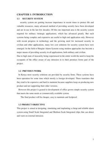
The system has to satisfy the following:1. Ensure the security of an office by deterring person intending to burglar andwarning the occupants of office of any unauthorized entry into theirpremise.2. Provide psychological satisfaction of being secure to the office occupant.1.4 PROJECT STRUCTUREProject was designed in the following modules:1. House Intrusion Module:This module consists of motion detectors placed strategically in concealedlocation this sensors when activated should activate the following devices in thefollowing sequence:·Activate buzzer to warn the occupants.·If present, activate the cameras·Finally it should set off the alarm2. The Control Unit Module:This is the decision making center that interprets the various inputs from thesensor and makes the appropriate logic decision.3. Arm and Disarm Module:This is for arming and disarming the system.4. Alarm Module:This is for warning and deterring the intruders.2
Block diagram:Arm/DisarmPowersupplyMicrocontroller (Poll/ Make Decisions)AlarmRangesensorRange SensorFigure 13
CHAPTER 2: THEORETICAL BACKGROUND2.1 Research2.1.1Burglar AlarmsMost burglar alarm systems run from a fixed 12V power supply. This is also thestandard operating supply voltage for usual subsystems such as any ultrasonic, PIR, heat,pressure or magnetic sensors etc also the majority of the Strobe flashing lights and sirensavailable also run from 12V. Bearing this knowledge in mind, my burglar alarm controlpanel should run from a 12V supply, and when an alarm output has to be activated, asupply of 12V should be supplied.A standard also exists for how input sensors operate. They normally use a normallyclosed (N.C.) loop for sensors, so that an alarm condition is signaled by a switch beingopened within the sensor and cutting the circuit. This also means that should a burglarcut the wires to a sensor, then the loop will be cut and an alarm signal is generated.Most commercial burglar alarms have the capability to monitor the input sensorsseparately, so that in the event of a burglary, it is known which sensors were and werenot triggered so that the point of entry and extent of break in can be deduced.2.1.2 MICROCONTROLLERA microcontroller (also MCU or µC) is a small computer on a single integrated circuitconsisting of a relatively simple CPU combined with support functions such as a crystaloscillator, timers, and watchdog, serial and analog I/O etc. Program memory in the formof NOR flash or OTP ROM is also often included on chip, as well as a, typically small,read/write memory.Thus, in contrast to the microprocessors used in personal computers and other highperformance applications, simplicity is emphasized. Some microcontrollers may operateat clock frequencies as low as 32 KHz, as this is adequate for many typical applications,enabling low power consumption (millwatts or microwatts). They will generally havethe ability to retain functionality while waiting for an event such as a button press orother interrupt; power consumption while sleeping (CPU clock and most peripherals off)may be just nanowatts, making many of them well suited for long lasting batteryapplications.4
Microcontrollers are used in automatically controlled products and devices, such asautomobile engine control systems, remote controls, office machines, appliances, powertools, and toys. By reducing the size and cost compared to a design that uses a separatemicroprocessor, memory, and input/output devices, microcontrollers make it economicalto digitally control even more devices and processes2.1.3 Analog to Digital ConverterAn analog-to-digital converter (abbreviated ADC, A/D or A to D) is a device whichconverts continuous signals to discrete digital numbers. The reverse operation isperformed by a digital-to-analog converter (DAC).Typically, an ADC is an electronic device that converts an input analog voltage (orcurrent) to a digital number. However, some non-electronic or only partially electronicdevices, such as rotary encoders, can also be considered ADCs. The digital output mayuse different coding schemes, such as binary, Gray code or two's complement binary2.2 TRANSDUCERSThis section deals with the various possible sensor designs and how they function andwhich could be appropriate for particular case.2.2.1 Infrared motion detector2.2.1.1 Passive Infrared sensor (PIR sensorPassive Infrared sensor (PIR sensor) is an electronic device that measures infrared (IR)light radiating from objects in its field of view. PIR sensors are often used in theconstruction of PIR-based motion detectors (see below). Apparent motion is detectedwhen an infrared source with one temperature, such as a human, passes in front of aninfrared source with another temperature, such as a wall.All objects emit what is known as black body radiation. It is usually infrared radiationthat is invisible to the human eye but can be detected by electronic devices designed forsuch a purpose. The term passive in this instance means that the PIR device does notemit an infrared beam but merely passively accepts incoming infrared radiation.5
In passive infrared motion detectors, a sensor containing an infrared-sensitivephototransistor is placed in the area to be protected. Circuitry within the sensor detectsthe infrared radiation emitted by the intruder's body and triggers the alarm. The problemwith using this type of detector is that it can be falsely triggered by warm air movementor other disturbances that can alter the infrared radiation levels in an area. In order toprevent this problem, newer systems use two infrared sensors which monitor differentzones within a protected area. Logic within system triggers the alarm only when the twozones are activated in sequence, as would occur if a person walked through the protectedarea.· Pyroelectric SensorsThe pyroelectric sensor is made of a crystalline material that generates a surface electriccharge when exposed to heat in the form of infrared radiation. When the amount ofradiation striking the crystal changes, the amount of charge also changes and can then bemeasured with a sensitive FET device built into the sensor. The sensor elements aresensitive to radiation over a wide range so a filter window is added to the TO5 packageto limit detectable radiation to the 8 to 14mm range which is most sensitive to humanbody radiation.Typically, the FET source terminal pin 2 connects through a pull down resistor ofabout 100 K to ground and feeds into a two stage amplifier having signal conditioningcircuits. The amplifier is typically bandwidth limited to below 10Hz to reject highfrequency noise and is followed by a window comparator that responds to both thepositive and negative transitions of the sensor output signal. A well filtered power sourceof from 3 to 15 volts should be connected to the FET drain terminal pin 1.6
Figure 1.1The PIR325 sensor has two sensing elements connected in a voltage buckingconfiguration. This arrangement cancels signals caused by vibration, temperaturechanges and sunlight. A body passing in front of the sensor will activate first one andthen the other element whereas other sources will affect both elements simultaneouslyand be cancelled. The radiation source must pass across the sensor in a horizontaldirection when sensor pins 1 and 2 are on a horizontal plane so that the elements aresequentially exposed to the IR source. A focusing device is usually used in front of thesensor.7
Figure 2.2Fresnel lensA Fresnel lens (pronounced Frennel) is a Plano Convex lens that has been collapsed onitself to form a flat lens that retains its optical characteristics but is much smaller inthickness and therefore has less absorption losses.8
Figure 2.3Our FL65 Fresnel lens is made of an infrared transmitting material that has an IRtransmission range of 8 to 14um which is most sensitive to human body radiation. It isdesigned to have its grooves facing the IR sensing element so that a smooth surface ispresented to the subject side of the lens which is usually the outside of an enclosure thathouses the sensor.The lens element is round with a diameter of 1 inch and has a flange that is 1.5 inchessquare. This flange is used for mounting the lens in a suitable frame or enclosure.Mounting can best and most easily be done with strips of Scotch tape. Silicone rubbercan also be used if it overlaps the edges to form a captive mount. There is no knownadhesive that will bond to the lens material.The FL65 has a focal length of 0.65 inches from the lens to the sensing element. It hasbeen determined by experiment to have a field of view of approximately 10 degreeswhen used with a PIR325 Pyroelectric sensor.9
Figure 2.4This relatively inexpensive and easy to use Pyroelectric Sensor and Fresnel Lens can beused in a variety of science projects, robots and other useful devices.10
2.2.1.2 Active Infrared Motion DetectorFigure 2.5Figure 2 shows the operation of an active infrared motion detector. In the active systemeach sensor consists of two housings. One housing contains an infrared-emitting diodeand an infrared-sensitive phototransistor. The other housing contains an infraredreflector. When positioned in front of an entrance to a protected area, the two housingsestablish an invisible beam. A person entering the area interrupts the beam causing analarm to be triggered. An active motion detector is much more reliable than a passiveone, but it requires careful alignment when it is installed. The detector can be falselytriggered if one of the housings moves slightly and causes a discontinuous beam.2.2.1.3 Magnetic reed switchesThough a house is well protected by installing break proof doors and windows it isnecessary to monitor the conditions of the door. This can be done by installing smallmagnetic switches inside the frame. This activates the alarm when it is disturbed.MicrocontrollerSwitch5 voltsframeDoor or Windowpermanent magnet.Figure 2.611
2.2.1.4 Breaking glass detectorModern glass break detectors consist of small microphone connected to a soundprocessor. The microphone is tuned to the frequency of breaking glass, and the processorlooks for a characteristic sound pattern. Additionally, the shock sensor detects the tinyshock wave that passes all through the building when a window suffers an impact. Onlywhen there is sound of breaking glass, and a shock wave, will the alarm sound. Thus,they are tremendously immune to environmental noise which might cause a false alarm.Glass break detectors must be located within a range of the glasses to protected, usuallyten feet or so. Additionally, heavy window treatments can significantly reduce theeffective range. Up to now the windows and doors are covered2.2.1.5 Ultrasonic Motion DetectorsUltrasonic transducers can be used to detect motion in an area where there are notsupposed to be any moving objects. This type of motion detector is most commonly usedin burglar alarm systems since they are very effective in this application.Figure 2.7 shows the operation of an ultrasonic motion detector. There are twotransducers: one emits an ultrasonic wave and the other picks up reflections from thedifferent objects in the area. The reflected waves arrive at the receiver in constant phaseif none of the objects in the area are moving. If something moves, the received signal isshifted in phase. A phase comparator detects the shifted phase and sends a triggeringpulse to the alarm.Ultrasonic motion detectors have certain advantages and disadvantages when comparedwith other types of motion detectors. The main advantages are that they are verysensitive and extremely fast acting. However, the largest problem with this type ofmotion detector is that it sometimes responds to normal environmental vibration that canbe caused by a passing car or a plane overhead. Some types of motion detectors useinfrared sensors to avoid this problem, but even these detectors have some problems12
Figure 2.72.2.1.5.1 LV-MaxSonar-EZ1High Performance Sonar Range FinderWith 2.5V - 5.5V power the LV-MaxSonar-EZ1 provides very short to long rangedetection and ranging, in an incredibly small package. The LV-MaxSonarEZ1detectsobjects from 0-inches to 254-inches (6.45-meters) and provides sonar range informationfrom 6-inches out to 254-incheswith 1-inch resolution. Objects from 0-inches to 6-inchesrange as 6-inches. The interface output formats included are pulse width output, analogvoltage output, and serial digital output.Features· Continuously variable gain for beam control and side lobe suppression· Object detection includes zero range objects· 2.5V to 5.5V supply with2mA typical current draw· Readings can occur up to every 50mS, (20-Hz rate)13
· Free run operation can continually measure and output range information· Triggered operation provides the range reading as desired· Designed for protected indoor environments· Sensor operates at 42 KHzBenefits·Very low cost sonar ranger·Reliable and stable range data·Sensor dead zone virtually gone·lowest power ranger·Quality beam characteristics·Mounting holes provided on the circuit board·Very low power ranger, excellent for multiple sensor or battery based systems·Can be triggered externally or internally·Sensor reports the range reading directly, frees up user processorBeam CharacteristicsPeople detection requires high sensitivity, yet a narrow beam angle requires lowsensitivity. TheLV-MaxSonarÒ-EZ1Ô balances the detection of people with a narrow beam width.Sample results for measured beam patterns are shown below on a 12-inch grid. ThedetectionPattern is shown for;(A) 0.25-inch diameter dowel, note the narrow beam for close small objects,(B) 1-inch diameter dowel; note the long narrow detection pattern,(C) 3.25-inch diameter rod, note the long controlled detection pattern,(D) 11-inch wide board moved left to right with the board parallel to the front sensorface and the sensor stationary. This shows the sensor’s range capability.Note: The displayed beam width of (D) is a function of the secular nature of sonar andthe shape of the board (i.e. flat mirror like) and should never be confused with actualsensor beam width.14
2.2.2 VARIOUS APPROACH.In order to design this project the main decision I need to make is what approach I willtake for the main alarm processing. In this chapter discussion of these designs dealt withand the reason why one design was chosen.2.2.2.1 Discrete Component Based DesignThis is one of the earliest forms of design which involve discrete components to buildthe digital systems.Disadvantages:·Huge power consumption·Large size of a complete system·Difficult to debug the complete systemThese systems includes the use of digital gates such as NAND, AND , NOR gatesetc .such as 74yy series.To build the system as stated the following components would be used· AND, OR gates· Delay circuits that can be implemented using flip-flop,555 timerICS.· Motion detector such as infrared motion detector would involveinfrared sensitive transistor that are biased to conduct by infraredemitted energyGenerally if these project where to be implemented using this way it would be quitebulkyexpensive and very hard to trouble shoot it in case of failure.2.2.2.2 COMPUTER BASED DESIGNComputers are very powerful device that can implement the control unit with minimumcomponents .the only important part is the interface between the sensors, switches, alarmand buzzer to the computer .This can be done through the 1pt printer port (parallel port)which has eight pins and five input pins. To get more pin one can add another input cardor include a microcontroller to communicate with the computer serially. By writingsoftware to manipulate the voltage at these pins one is able to scan the conditions of the15
sensor and perform the appropriate action .However to interface the circuit to computerone as to be careful as the parallel port only accept up to a maximum of 5volts.whilethings like relay switches ear usually accompanied by the transient which are be harmfulto the printer port. These demands use of optiosolator to electrically separate thecomputer from the external circuitsLimitations for computer based design:·High cost of computer·The computer has to be continuously, this means the need for dedicatedcomputer which is uneconomical·Due to constant power losses there is need to include power backupswhich and the cost.2.2.2.3 MICROCONTROLER BASED DESIGNCircumstances that we find ourselves in today are in the field of microcontrollers whichhad their beginnings in the development of technology of integrated circuits. Thisdevelopment has made it possible to store hundreds of thousands of transistors in to onechip. That was a perquisite for production of microprocessors, and the first computerswere made by adding external peripheral such as memory, input –output lines timers andother .further increasing of the volume of the package resulted in creation of integratedcircuits .these integrated circuits contained both processor and peripherals. That is howthe first chip containing a microcomputer, or what would later be known asmicrocontroller came about.Microcontroller differs from microprocessor in many ways. First and fore mostimportant is its functionality. In order for a microprocessor to be used other componentssuch as memory, or components for receiving and sending data must be added to it .inshort that means that microprocessor is very heat of computer in other handmicrocontroller is designed to be all of that in one. No other external component areneeded for its application because all necessary peripherals are already built into it ,thuswe save the time and space needed to construct devices.16
In this project microcontroller will form the heart of the system. This would perform thefunction of polling sensors interpreting input and perform the necessary action. This isso because using instead of using intelligent sensor s that would be reporting to centralunit the project will utilize dump sensors.Most microcontrollers come with several ports than several bit wide for example in thiscase the Atmega168 from Atmel Company has two 8bit ports and one 7bit port.These ports can be connected to the various sensors whose high condition are 5.5voltsand low are 1.8volts.Advantages of microcontroller based design·Can be produced in small packages that users can be able to configure on theirown·Low Power Consumption thus cheap to maintain can be run by batteries– Active Mode: 250 μA at 1 MHz, 1.8V15 μA at 32 kHz, 1.8V (including Oscillator)– Power-down Mode: 0.1μA at 1.8V·They stand alone equipments that require little maintenance.·They are easy to debug in case of fault as they consist of very few copheriperialcomponents.·They are easy to upgrade due to compatibility of AVR microcontrollers ofdiffered series for example the code written for ATmega48 can be run inATmega88 with minor modification.·The ATmega48/88/168 has Advanced RISC Architecture (reduced instruction setcomputer).– 131 Powerful Instructions – Most Single Clock Cycle Execution– 32 x 8 General Purpose Working Registers– Fully Static Operation– Up to 20 MIPS Throughput at 20 MHz– On-chip 2-cycle MultiplierThus they are easy to learn and develop software having in mind the need toshorten development time and reduce time to market. This is very importantaspect in modern world.17
High Endurance Non-volatile Memory segments– 4/8/16K Bytes of In-System Self-programmable Flash program memory– 256/512/512 Bytes EEPROM– 512/1K/1K Bytes Internal SRAM– Write/Erase cycles: 10,000 Flash/100,000 EEPROM– Data retention: 20 years at 85 C/100 years at 25 C– Optional Boot Code Section with Independent Lock BitsIn-System Programming by On-chip Boot ProgramTrue Read-While-Write Operation– Programming Lock for Software SecurityThus reduce cost of field up grades since the cost of upgrading a system code can bedramatically reduced. with very little effort and planning, flash based system can bedesigned to have code upgrades in the field for AT mega FLASH device the entirecode can be rewritten with new code new code segments and parameter tables can beeasily added in program memory areas left blank for upgrade purpose, only portionof code (such as key algorithm) require update.·Calibration and customization of your systemCalibration need not be done only in factory .during installation of the systemcan be calibrated to actual operating environment. In fact recalibration can beeasily done during periodic servicing and maintenance.Customization need not to be done in factory only. In many situationscustomizing a product at installation time is very useful. .a good example is ahome or car security systems where ID code, access code and other suchinformation can be burned in after the actual configuration is determined.·Add unique Id code to your system during manufacturing.·Many products require a unique ID number or a serial number. An exampleapplication would be remote keyless entry device. Each transmitter has a unique“binary key” that makes it very easy to program in the access code at the veryend of the manufacturing process and prior to final test. Serial number, revisioncode, date code, manufacture ID and a variety of other useful information canalso be added to any product for traceability18
CHAPTER 3: SYSTEM DESIGN3.1 Microcontroller circuit design.Considering the advantages of the microcontroller motioned in chapter twoearlier. In this project choose to use ATmega168 microcontroller from ATMELCompany as my control unit.3.1.1 Features of AVR ATmega 168 microcontrollerIn this project microcontroller used is AT mega 168. This belongs to a class of 8 - bitsMicrocontrollers of advanced RISC (reduced instruction set computer) Architecture. Itsgeneral structure is shown on the following block diagram representing the basic blocks.BLOCK DIAGRAM:Figure 3.1The AVR core combines a rich instruction set with 32 general purpose workingregisters. All the 32 registers are directly connected to the Arithmetic Logic Unit (ALU),allowing two independent registers to be accessed in one single instruction executed in19
one clock cycle. The resulting architecture is more code efficient while achievingthroughputs up to ten times faster than conventional CISC microcontrollers.The ATmega48/88/168 provides the following features: 4K/8K/16K bytes of In-SystemProgrammableFlash with Read-While-Write capabilities, 256/512/512 bytes EEPROM, 512/1K/1KbytesSRAM, 23 general purpose I/O lines, 32 general purpose working registers, threeflexibleTimer/Counters with compare modes, internal and external interrupt a serialprogrammableUSART, a byte-oriented 2-wire Serial Interface, an SPI serial port, a 6-channel 10-bitADC (8channels in TQFP and QFN/MLF packages), a programmable Watchdog Timerwith internal Oscillator, and five software selectable power saving modes. The Idlemode stops the CPU while allowing the SRAM, Timer/Counters, USART, 2-wire SerialInterface, SPI port, and interrupt system to continue functioning. The Power-down modesaves the register contents but freezes the Oscillator, disabling all other chip functionsuntil the next interrupt or hardware reset.In Power-save mode, the asynchronous timer continues to run, allowing the user tomaintain a timer base while the rest of the device is sleeping. The ADC Noise Reductionmode stops the CPU and all I/O modules except asynchronous timer and ADC, tominimize switching noise during ADC conversions. In Standby mode, thecrystal/resonator Oscillator is running while the rest of the device is sleeping. Thisallows very fast start-up combined with low power consumption.The device is manufactured using Atmel’s high density non-volatile memorytechnology. TheOn-chip ISP Flash allows the program memory to be reprogrammed In-System throughan SPI serial interface, by a conventional non-volatile memory programmer, or by anOn-chip Boot program running on the AVR core. The Boot program can use anyinterface to download the application program in the Application Flash memory.Software in the Boot Flash section will continue to run while the Application Flashsection is updated, providing true Read-While-Write operation. By combining an 8-bit20
RISC CPU with In-System Self-Programmable Flash on a monolithic chip, the AtmelATmega48/88/168 is a powerful microcontroller that provides a highly flexible and costeffective solution to many embedded control applications.The ATmega48/88/168 AVR is supported with a full suite of program and systemdevelopment tools including: C Compilers, Macro Assemblers, and ProgramDebugger/Simulators, In-Circuit Emulators, and Evaluation kits.·Program Memory (FLASH) – For storing a written program.Since memory made in FLASH technology can be programmed and cleared morethan once, it makes this microcontroller suitable for device development.·EEPROM – data memory that needs to be saved when there is no supply.It is usually used for storing important data that must not be lost if power supplysuddenly stops. For instance, one such data is assigned password in securityapplications. If during a loss of power this data was lost, we would have to makethe adjustment once again upon return of supply. Thus our device looses on self –reliance.·RAM – Data memory used by a program during its execution.·PORTS are physical connections between the microcontroller and the outsideworld. Port B and port D has eight pins and Port C has seven pins.·FREE – RUN TIMERS is an 8 – bit register inside a microcontroller that worksindependently of the program. On every sixteenth clock of oscillator itincrements its value until it reaches the maximum (555), and then it startscounting again from zero. As we know the exact timing between each twoincrements of the timer contents, timer can be used for measuring time which isvery useful with some devices.·CENTAL PROCESSING UNIT has a role of connective element betweenother blocks in the microcontroller. It coordinates the work of other blocks andexecutes the user program.·CISC, RISCIt has already been said that AT mega 168 has advanced RISC architecture. Thisterm is often found in computer literature, and it needs to be explained here inmore detail. Harvard architecture is a newer concept than von – Neumann’s. It21
rose out of the need to speed up the work of a microcontroller. In Harvardarchitecture, data bus and address bus are separate. Thus a greater flow of data ispossible through the central processing unit, and of course, a greater speed work.Separating a program from data memory makes it further possible forinstructions not to have to be 8 – bit words. PICI16F84 uses 14 bits forinstructions which allows for all instructions to be one word instructions. It isalso typical for Harvard architecture to have fewer instructions than von –Neumann’s, and to have instructions usually executed in one cycle.Microcontrollers with Harvard architecture are also called “RISC microcontrollers”.RISC stands for Reduced Instruction Set Computer. Microcontrollers with von –Neumann’s architecture are called “CISC microcontrollers”. Title CISC stands forcomplex Instruction Set ComputerSince AT mega 168 is a RISC microcontroller, that means that it has reduced set ofinstructions,. (131 powerful instructions most single clock circle execution) all of theseinstructions are executed in one cycle except for jump and branch instructions.3.1.1.1 ApplicationsATmega microcontrollers perfectly fit many uses, from automotiveindustries and controlling home appliances to industrial instruments, remotesensors, electrical door locks and safety devices. It is ideal for smart cards as wellas for battery supplied devices because of its low consumption.EEPROM memory makes it easier to apply microcontrollers to devices wherepermanent storage of various parameters is needed (Codes for passwords,receiver frequencies, e.tc)Low cost, low consumption, easy handling and flexibility make ATmegaMicrocontrollers applicable even in areas where microcontrollers had notpreviously been considered (for example: timer functions, interface replacementand in larger systems, coprocessor applications, etc)In system programmability of this chip (along with using two pins in datatransfer makes
used in a variety of science projects, robots and other useful devices. 11 2.2.1.2 Active Infrared Motion Detector Figure 2.5 Figure 2 shows the operation of an active infrared motion detector. In the active system each sensor consists of two housings. One housing contains an infrared-emitting diode