Transcription
Need a part CLICK HEREwww.shop.mobilemobilityservices.comLift ChairService GuideThis Service Guide contains:TroubleshootingReplacement InstructionsIllustrated Parts DiagramsNeed parts CLICK HERE
REVA 082012Contact Information:Golden Technologies401 Bridge StreetOld Forge, PA 18518Toll-free: 800-624-6374Fax: 800-628-5165Lift Chair/Bed Tech: x645Mobility Tech: x648VA Tech: x647Email: parts@goldentech.com1
REVA 082012Table of ContentsAbout the Lift Chair Service Guide.3Lift Chair Components.3-5General Trouble Shooting.6Tools Required.6Models Quick Reference.7Replacement Instructions.8-15Smart Tek Hand Control.8Hand Control Extension Wire.8Back Assembly.9Control Box.9Lift Motor.9Lift Frame.10Arm Assembly.10-11Scissor Mechanism.11-12Recline Bar.12-13Seat Assembly.13-14Recline Straps.14-15Scissor Mechanism Parts.16Electrical Systems.17-22Single Motor.17Dual Motor.18Triple Motor.19Heat and Massage.20MaxiComfort.21Trouble Shooting with SMART TEK.22Lift 5000C.32-34LM502.35-39LM906.40-41MaxiComfort Recline Mechanism.42Power Connections.43Back Installation.43MaxiComfort Back Installation.44Hand Controls.45-47Grease Points.48Lift Chair Cut Away.49Lift Chair Boxing Instructions.50-512
REVA 082012About the Lift Chair Service GuideThis service guide provides you with the information necessary to repair Golden Technologies 3position, 2-position, and MaxiComfort recline lift chairs. The troubleshooting scenarios in this manualconsist of procedures that enable you to systematically trace and correct faults in the system,replacement procedures, and exploded views of available parts. Most replacement instructions applyto all the lift chairs in this service manual, but some of them are specific to individual chairs.Before troubleshooting, check the following: Make sure that the lift chair is plugged into a working wall outlet. Check the wall outlet circuit breaker. Visually check terminals for corrosion. Check wires for missing insulation. Check connectors for unseated pins. Ensure LED lights are on. (Refer to “Trouble Shooting with SMART TEK” on page 22).Information required prior to making a service call: Serial Number Date of Purchase Description of the problem with the lift chairLift Chair ComponentsLift chairs are powered by 24V DC transformers that plug into standard wall outlets and operate onstandard 120V AC electricity. The lift chair control system is made up of the following components: Motor(s) Transformer Massage Unit* Hand Control Battery Backup Wire* Control Unit* Extension Wire Heat Unit* Junction Box** Only on Selected ModelsComponent: MotorLocation: Between the lift frame and the seat.Function: Provides lift and recline.Connections: Each motor is physically connected to the chair through the lift frame and the motorstraps. Each motor is electrically connected to either a control unit or directly to the hand control.Failure Signs: Chair will not lift and/or recline. Motor may become noisy just before failure.Tests: See “Trouble Shooting with SMART TEK” on page 22.Expected Readings: See “Trouble Shooting with SMART TEK” on page 22.Serviceable: Must be replaced.Component: Hand Control (Lift/Recline or Recline Only)Location: On the arm of the chair.Function: Provides user interface for lift/recline or recline only.Connections: Connected to either the control unit or the motor.Failure Signs: Chair will not lift and/or recline.Tests: See “Trouble Shooting with SMART TEK” on page 22.Expected Readings: See “Trouble Shooting with SMART TEK” on page 22.Serviceable: Must be replaced.3
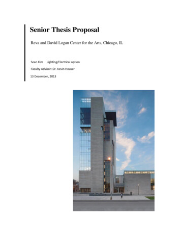
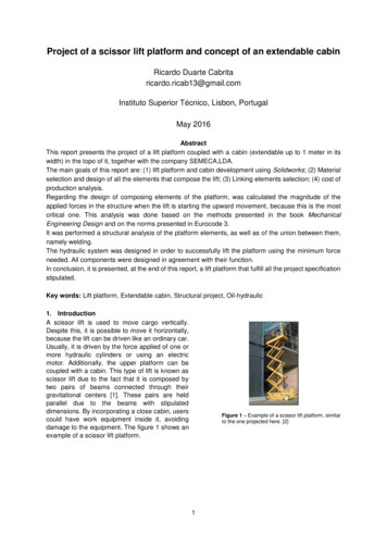
REVA 082012Component: Extension WireLocation: Between the lift frame and the chair frame.Function: Provides connection from the hand control to the motor or control box.Connections: From the quick disconnect in the pocket to the motor or control box.Failure Signs: Chair will not lift/recline.Tests: Test continuity.Expected Readings: Open Circuit.Serviceable: Must be replaced.Component: TransformerLocation: Next to chair.Function: Converts AC to DC. Also provides power during a power failure.Note: Power during a power failure only applies to the lift/recline or recline only functions.Connections: Wall outlet and either control box or motor.Failure Signs: Chair will not operate.Tests: Test for voltage at connection to chair.Expected Readings: Approximately 27VDC.Serviceable: Must be replaced.Component: Control Box (500-lb. chair only)Location: On the lift frame.Function: Provides connectivity for motors, hand control,and transformer.Connections: Connected to the motor(s), hand control,and transformer.Failure Signs: Chair will not lift and/or recline.Clicking noise. Motors out of sync.Tests: AC VoltageExpected Readings: 27 - 32 VAC. See figure 1.Serviceable: Must be replaced.POSITIVENEGATIVEComponent: Heat PadFigure 1. Control BoxLocation: On the chair seat.Function: Provides heat.Connections: Connected to the control box.Failure Signs: No heat.Tests: Resistance.Expected Readings: (Far Infrared Heat only, 1 - 6 ohms across the two connector pins).Serviceable: Must be replaced.Component: Massage UnitLocation: On the seatback or the seat.Function: Vibrates to provide massage.Connections: Connected to the junction box.Failure Signs: Massage will not work when selected.Tests: Check for DC voltage.Expected Readings: Approximately 13.8 DC Volts.Serviceable: Must be replaced.4
REVA 082012Component: Hand Control (Heat/Massage or Infrared Heat Only)Location: On the arm of the chair.Function: Provides user interface for heat/massage or Infrared heat only.Connections: Connected to the control box.Failure Signs: Heat/Massage or Infrared Heat Only will not work.Tests: See “Hand Controls” on pages 45-47. For a more complete guide, refer to the manufacturer’sowner’s manual.Expected Readings: See “Hand Controls” on pages 45-47. For a more complete guide, refer tothe manufacturer’s owner’s manual.Serviceable: Must be replaced.Battery Back Up System1. Batteries should be replaced after one use.2. Batteries should be changed yearly.For a complete explanation of the battery back up system, refer to the owner’s manual.5
REVA 082012General Trouble ShootingProblem: 1Chair is in the lift position and will not descend, or chair is in the recline position and will not lift.Solution:If the chair is stuck in the lift position, press the down button; if the chair is stuck in the reclineposition, press the up button. While pressing the appropriate button, listen to hear if the motor isrunning.Ensure LED lights are on. (Refer to “Trouble Shooting with SMART TEK” on page 22).Problem 2If you don’t hear the motor running, follow these steps.A) Check to see if the chair is securely plugged in.B) See if the outlet is activated by a wall switch.C) Try plugging the chair into a different outlet. (Sometimes the socket is worn and will nothandle the amps needed for operation.)D) Check wiring on both power cord for motor and switch cord for breakage or fraying.E) Plug the new hand control into motor or into extension and try for chair response.F) If still no response, see “Trouble Shooting with SMART TEK” on page 22.Problem 3If you hear the motor running, but the chair won’t move or partially moves, check for the following:A) Inspect lift frame for possible breakage.B) Inspect push tube or gear casing for breakage.C) Gears may be stripped in gear casing in motor assembly.D) Push tube may be stripped or the fork head may be broken.Tools Required:The following tools are needed to service Golden Technologies lift chairs. # 8, 9 or 10 flat head screw driver P2 & P3 Phillips head screw driver T30 torx bit Wired or wireless drill (Note: Driver bits can be used to speed up the repair process). Chair stand Spare hair pins Zip ties 7/16 box head wrench 3/8 box head wrench 1/2 box head wrench Needle nose pliers Volt meter Clippers or scissors Retracto knife Spare rags Large vice grip White lithium grease or Zep 2000If servicing a lift chair with the MaxiComfort mechanism, you will also need: 7/16 & 3/8 ratchet wrench 5/32 Allen wrench6
REVA 082012Models Quick MediumLM5100MediumSingleStandard US2 Button3 d US2 Button3 rd US2 Button3 rd US2 Button3 d US2 Button3 rd US2 Button3 wayPR-752SignatureMediumLM5100MediumSingleStandard US2 Button3 wayPR-451SignatureMediumLM5100MediumSingleStandard US2 Button3 wayPR-906SignatureMed/LargeLM906None906Standard US2 Button906PR-756MCMaxi ComfortMediumLM5100MediumMaxiStandard USAuto DriveMaxiPR-756LMaxi ComfortLargeLM5120LargeMaxiStandard USAuto DriveMaxiPR-506Maxi ComfortMediumLM5100MediumMaxiStandard USAuto DriveMaxiPR-505JPMaxi ComfortJr. PetiteLM5100PetitMaxiStandard USAuto DriveMaxiPR-505SMaxi ComfortSmallLM5100SmallMaxiStandard USAuto DriveMaxiPR-505MMaxi ComfortMediumLM5100MediumMaxiStandard USAuto DriveMaxiPR-505LMaxi ComfortLargeLM5120LargeMaxiStandard USAuto DriveMaxiPR-510Maxi ComfortMediumLM5100MediumMaxiStandard USAuto DriveMaxiPR-501JPComforterJr. PetiteLM5100PetitSingleStandard US2 Button3 wayPR-501SComforterSmallLM5100SmallSingleStandard US2 Button3 d US2 Button3 wayPR-501LComforterLargeLM5120LargeSingleStandard US2 Button3 wayPR-501TComforterTallLM5120LargeSingleStandard US2 Button3 wayPR-501S-23Comforter WideWideLM5120LargeSingleStandard US2 Button3 wayPR-501M-26DComforter WideMediumLM6111Medium/wideDualStandard US2 Button3 wayPR-501L-26DComforter WideLargeLM6111Medium/wideDualStandard US2 Button3 wayPR-501T-28DComforter WideTallLM6111Tall/WideDualStandard US2 Button3 wayPR-502Comforter WideWideLM502502TripleStandard US6 rd US2 Button2 wayPR-355MValueMediumLM5100MediumSingleStandard US2 Button3 wayPR-355LValueLargeLM5120LargeSingleStandard US2 Button3 wayPR-359MValueMediumLM5100MediumSingleStandard US2 Button3 wayPR-359LValueLargeLM5120LargeSingleStandard US2 Button3 way
REVA 082012Replacement InstructionsSmart Tek Hand Control ReplacementTools Needed: None1.Unplug the transformer from the wall outlet.2. Unplug the motor power cable.3. Reach down into the pocket until you feel the disconnect latch on the extension cable.4. Pull back on the disconnect latch.5. Put one hand on the back of the extension wire plug base and one on the hand control plug base andpull the two pieces apart.6. Plug in the new Smart Tek hand control to the extension cable.7. Push forward on the disconnect latch. Make sure it engages fully with the hand control plug base.8. Reconnect the motor power cable.9. Plug the transformer into the wall outlet and test the hand control.Hand Control Extension Wire ReplacementTools Needed: Phillips head screwdriver, wire cutter, staple remover, stapler, zip ties, and a chair stand.1.Unplug the transformer from the wall outlet.2. Unplug the transformer from the battery backup cable.3. Reach down into the chair’s side pocket until you feel the disconnect latch on the hand controlextension.4. Pull back on the disconnecting latch.5. Put one hand on the back of the extension wire plug base and one on the hand control plug base andpull the two pieces apart.6. Gently push the chair over onto the footrest, turn it upside down or, gently push it over onto its side,opposite of the hand control.7. Use a Phillips screwdriver to remove the wire clamp used to secure the extension cable to the bottomof the armrests. Make sure you save the clamp and screw.8. Remove a few staples on the arm assembly to allow the extension wire to be pulled out through thefabric pocket.9. Pull the extension cable through the fabric pocket.10. Locate the zip ties that hold the extension wire to the lift frame. Note their location.11. Cut these ties.12. Unplug the extension cable from the control box.13. Plug the new extension cable into the control box.14. Secure it to the lift frame with zip ties. Use the same locations as the old extension cable.15. Insert the extension cable into the fabric pocket.16. Reinstall the staples that were removed in step 8.17. Reinstall the wire clamp.18. Turn the chair back over onto its legs.19. Plug in the Smart Tek hand control to the extension cable.20. Push forward on the disconnecting latch. Make sure it engages fully with the hand control plug base.21. Clip the Smart Tek hand control to the black plastic hook on the side of the chair arm.22. Plug the battery backup back into the transformer.23. Plug the transformer back into the wall outlet and test.8
REVA 082012Back Assembly Replacement (500-lb. and 3-position)Tools needed: 7/16 in. socket wrench1. Press the Up Button on the hand control until the footrest is about parallel to the floor.2.Unplug the transformer from the wall outlet.3. Using the 7/16 in. socket wrench, remove the (2) flange lock nuts located on both sides of the back.4. Pull the back flap away from the Velcro.5. Work the back assembly out one side at a time pulling the threaded studs out of the scissormechanisms.6. Install new back.Control Box Replacement (500-lb. only)Tools needed: Wire cutters, replacement zip ties, and a chair stand.1.Unplug the transformer from the wall outlet.2. Unplug the battery backup cable from the transformer.3. Gently push the chair over onto the footrest, turn it upside down or, gently push it over onto its side,opposite of the hand control.4. Unplug the motor(s), hand control extension, and battery backup from the control box.5. Cut the wire ties that fasten the control box and the motor(s) to the lift frame and remove it.6. Use wire ties to fasten a new control box onto the lift frame.7. Plug the motor(s), hand control extension, and battery backup into the new control box.8. Gently turn the chair back over.9. Plug the battery backup cable into the transformer.10. Plug the transformer into the wall outlet and test.Lift Motor ReplacementTools needed: Needle nose pliers, zip ties, and a chair stand.1.Unplug the transformer from the wall outlet.2. Unplug the battery backup cable from the transformer.3. Gently push the chair over onto the footrest, turn it upside down or, gently push it over onto its side,opposite of the hand control.4. Unplug the motor(s) from the control unit (501M26, 501L26, 501T28), or from the hand controlextension and the transformer.5. Remove the hitch pin and the clevis pin that fastens the bottom of the motor(s) to the lift frame.6. Remove the hitch pin, the clevis pin, washers, and spacers that fasten the top of the motor(s) to therecline straps.7. Use the hitch pin and clevis pin to fasten the bottom of the new motor to the lift frame.8. Use the hitch pin, clevis pin, washers, and spacers to fasten the top of the lift recline to the reclinestraps.9. Connect the new motor(s) to the control unit.10. Turn the chair over onto the lift frame.11. Plug the battery backup cable into the transformer.12. Plug the transformer into the wall outlet and test.9
REVA 082012Lift Frame ReplacementTools needed: Needle nose pliers, T30 Torx screw bit, wire cutters, replacement zip ties, and a chairstand.1.Unplug the transformer from the wall outlet.2. Unplug the battery backup cable from the transformer.3. Gently push the chair over onto the footrest, turn it upside down or, gently push it over onto its side,opposite of the hand control.4. Unplug the motor(s), hand control extension, and battery backup from the control box.5. Cut the wire ties that fasten the control box to the lift frame and remove it (500-lb. only.)6. Remove the eight (8) T30 lag screws that hold the lift frame to the arm assembly.7. Cut the wire ties that hold the hand control extension wire to the frame and place the wire to the side.8. Remove the hitch pin(s), the clevis pin(s), and the washers that fasten the recline strap(s) to therecline bar.9. Lift the lift frame out of the chair shell.Note: When installing the new lift frame the footboard must be completely closed when you fastenthe lift frame to the armrest assembly or the footboard will not close properly.10. Cut the wire ties that fasten the motor cables to the lift frame.11. Remove the hitch pin(s) and the clevis pin(s) that fasten the bottom of the motor(s) to the lift frame.12. Remove the hitch pin(s), the clevis pin(s), spacers, and washers that fasten the recline straps(s) tothe lift frame.13. Use the hitch pin(s), the clevis pin(s), spacers, and washers to fasten the recline strap(s) to the newlift frame.14. Use the hitch pin(s) and the clevis pin(s) to fasten the bottom of the motor(s) to the new lift frame.15. Place the new lift frame onto the chair shell.16. Use the hitch pin(s), the clevis pin(s), and the washers to fasten the recline strap(s) to the reclinebar.17. Use the eight (8) T30 lag screws to fasten the lift frame to the arm assembly.18. Use two wire ties to fasten the hand control extension to the lift frame.19. Use wire ties to fasten the control box to the lift frame.20. Plug the motor(s), hand control extension, and battery backup into the control box.21. Gently push the chair back over.22. Plug the battery backup cable into the transformer.23. Plug the transformer into a wall outlet and test.Arm Assembly ReplacementTools needed: Needle nose pliers, P2 Phillips screwdriver, T30 screw bit, wire cutters, zip ties, 3/8 in.socket, a stool or stand for placing the chair upside down.1.Unplug the transformer from the wall outlet.2. Unplug the battery backup cable from the control box.3. Reach down into the chair’s side pocket until you feel the disconnect latch on the hand controlextension.4. Pull back on the disconnecting latch.5. Put one hand on the back of the extension wire plug base and one on the hand control plug base andpull the two pieces apart.6. Gently push the chair over onto the footrest, turn it upside down or, gently push it over onto its side,opposite of the hand control.10
REVA 0820127. Use a Phillips screwdriver to remove the wire clamp used to secure the extension cable to thebottom of the armrests. Make sure you save the clamp and screw.8. Remove a few staples on the arm assembly to allow the extension wire to be pulled out through thefabric pocket.9. Pull the extension cable through the fabric pocket.10. Remove the eight (8) T30 lag screws that hold the lift frame to the arm assembly.11. Remove the hitch pin(s), the clevis pin(s), and the washers that fasten the recline strap(s) to therecline bar.12. Lift the lift frame out of the chair shell and place it off to the side.13. Use the 3/8 in. socket to remove the four (4) bolts that fasten each scissor mechanism to the armassembly.While this next step can be done alone, it does require extra attention. You mustremove the arm assembly without twisting the frame. Excessive twisting will cause the boardholding the arms together to snap.14. Stand behind the chair and pull the arms away from the chair being careful not to get the materialsnagged in the scissor mechanisms.15. Place the arm assembly to the side.16. Place the new arm assembly in place so that the bolt holes in the scissor mechanisms line up with thebolt holes in the armrest.17. Install the four (4) bolts that fasten each scissor mechanisms to the new arm assembly.18. Make sure the footboard is completely closed.Note: When installing the lift frame the footboard must be completely closed when you fasten the liftframe to the armrest assembly or the footboard will not close properly.19. Place the lift frame onto the chair shell.20. Use the hitch pin(s), the clevis pin(s), and the washers to fasten the recline strap(s) to the reclinebar.21. Use the eight (8) T30 lag screws to fasten the lift frame to the arm assembly.22. Reinstall the staples that were removed in step 8.23. Reinstall the wire clamp.24. Gently turn the chair back over onto its legs.25. Plug in the Smart Tek hand control to the extension cable.26. Push forward on the disconnecting latch. Make sure it engages fully with the hand control plug base.27. Clip the Smart Tek hand control to the black plastic hook on the side of the chair arm.28. Plug the battery backup back into the control box.29. Plug the transformer back into the wall outlet and test.Scissor Mechanism ReplacementTools needed: Needle nose pliers, P2 Phillips screwdriver, T30 screw bit, wire cutters, zip ties, 3/8 in.socket, a stool or stand for placing the chair upside down.1.Unplug the transformer from the wall outlet.2. Unplug the battery backup cable from the transformer.3. Reach down into the chair’s side pocket until you feel the disconnect latch on the hand controlextension.4. Pull back on the disconnecting latch.5. Put one hand on the back of the extension wire plug base and one on the hand control plug base andpull the two pieces apart.11
REVA 0820126. Gently push the chair over onto the footrest, turn it upside down or, gently push it over onto its side,opposite of the hand control.7. Unplug the transformer and the hand control extension from the motor (or control box.)8. Remove the eight (8) T30 lag screws that hold the lift frame to the arm assembly.9. Remove the hitch pin(s), the clevis pin(s), and the washers that fasten the recline strap(s) to therecline bar.10. Remove the hand control extension wire clamp.11. Lift the lift frame out of the chair shell and place it off to the side.12. Use the 3/8 in. socket to remove the four (4) bolts that fasten each scissor mechanism to the armassembly.While this next step can be done alone, it does require extra attention. You mustremove the arm assembly without twisting the frame. Excessive twisting will cause the boardholding the arms together to snap.13. Stand behind the chair and pull the arms away from the chair being careful not to get the materialsnagged in the scissor mechanisms.14. Place the arm assembly to the side.15. Use the Phillips screwdriver to remove the screws that fasten the scissor mechanism to thefootboard.16. Use the 3/8 in. socket to remove the bolts that fasten the scissor mechanism to the seat and to thefootboard.17. Use the 3/8 in. socket to install the bolts that fasten the new scissor mechanism to the seat and thefootboard.18. Use the Phillips screwdriver to install the screws that fasten the new scissor mechanism to thefootboard.19. Place the arm assembly in place so that the bolt holes in the scissor mechanisms line up with the boltholes in the armrest.20. Install the four (4) bolts that fasten each scissor mechanisms to the arm assembly.21. Make sure the footboard is completely closed.Note: When installing the lift frame the footboard must be completely closed when you fasten the liftframe to the armrest assembly or the footboard will not close properly.22. Place the lift frame onto the chair shell.23. Use the hitch pin(s), the clevis pin(s), and the washers to fasten the recline strap(s) to the reclinebar.24. Use the eight (8) T30 lag screws to fasten the lift frame to the arm assembly.25. Reinstall the hand control extension wire clamp.26. Plug the transformer and hand control extension into the motor or control box.27. Plug the battery backup back into the transformer.28. Plug the transformer back into the wall outlet and test.29. Reinstall the seatback (if removed).Recline Bar ReplacementTools needed: Needle nose pliers, P2 Phillips screwdriver, T30 screw bit, wire cutters, zip ties, 3/8 in.socket, a stool or stand for placing the chair upside down.1.Unplug the transformer from the wall outlet.2. Unplug the battery backup cable from the transformer.12
REVA 0820123. Reach down into the chair’s side pocket until you feel the disconnect latch on the hand controlextension.4. Pull back on the disconnecting latch.5. Put one hand on the back of the extension wire plug base and one on the hand control plug base andpull the two pieces apart.6. Gently push the chair over onto the footrest, turn it upside down or, gently push it over onto its side,opposite of the hand control.7. Remove the eight (8) T30 lag screws that hold the lift frame to the arm assembly.8. Remove the hitch pin(s), the clevis pin(s), and the washers that fasten the recline strap(s) to therecline bar.9. Remove the hand control extension wire clamp.10. Lift the lift frame out of the chair shell and place it off to the side.11. Use the 3/8 in. socket to remove the four (4) bolts that fasten each scissor mechanism to the armassembly.While this next step can be done alone, it does require extra attention. You mustremove the arm assembly without twisting the frame. Excessive twisting will cause the boardholding the arms together to snap.12. Stand behind the chair and pull the arms away from the chair being careful not to get the materialsnagged in the scissor mechanisms.13. Place the arm assembly to the side.14. Use the 1/2 in. socket to remove the bolts that fasten the recline bar to the seat.15. Use the 1/2 in. socket to install the bolts that fasten the new recline bar to the seat.16. Place the arm assembly in place so that the bolt holes in the scissor mechanisms line up w
REVA_082012 5 Component: Hand Control (Heat/Massage or Infrared Heat Only) Location: On the arm of the chair. Function: Provides user interface for heat/massage or Infrared heat only. Connections: Connected to the control box. Failure Signs: Heat/Massage or Infrared Heat Only will not work. Tests: See "Hand Controls" on pages 45-47.For a more complete guide, refer to the manufacturer's