Transcription
ManualModel 1212EBrushed DC Permanent MagnetMotor Controller» Software Device Profile: 1.0.0.0 «Curtis Instruments, Inc.200 Kisco AvenueMt. Kisco, NY 10549www.curtisinstruments.comRead Instructions Carefully!Specifications are subject to change without notice. 2022 Curtis Instruments, Inc. Curtis is a registered trademark of Curtis Instruments, Inc. Kohler is a registered trademark of Kohler Co. The design and appearance of the products depicted herein are the copyright of Curtis Instruments, Inc.53250 Rev A July 2022
TABLE OF CONTENTSCHAPTERS1: OVERVIEW. 1KEY FEATURES. 2TECHNICAL SUPPORT. 4CONVENTIONS. 4NUMERAL SYSTEM NOTATION. 4MISCELLANEOUS CONVENTIONS. 42: INSTALLATION, WIRING, AND I/O CONFIGURATION. 5MOUNTING THE CONTROLLER. 5HIGH CURRENT CONNECTIONS. 6LOW CURRENT CONNECTIONS. 78-PIN I/O CONNECTOR (J1). 716-PIN I/O CONNECTOR (J2). 8WIRING DIAGRAM. 9I/Os. 10SWITCH INPUTS. 10FLEXIBLE SWITCH INPUTS. 10ANALOG INPUTS. 12POTENTIOMETER CIRCUIT. 13COIL DRIVERS. 14THROTTLE INPUT. 14FORWARD AND REVERSE INPUTS. 15KEYSWITCH. 16EMERGENCY STOP SWITCH. 16CIRCUITRY PROTECTION FUSES. 16INTERLOCK INPUT. 17EMERGENCY REVERSE INPUTS. 17pg. iiCurtis Model 1212E – July 2022
TABLE OF CONTENTS cont’dEM BRAKE. 18MODE INPUT. 18CHARGER INHIBIT INPUT. 19I/O GROUND. 19HYDRAULIC FUNCTIONS. 19INHIBIT INPUT. 21STEERING SPEED LIMIT INPUT. 22HORN DRIVER AND INPUT. 24INCHING MODE INPUT. 25CREEP MODE INPUT. 25BDI OUTPUT. 26CAN CONNECTIONS. 263: APPLICATION-SPECIFIC FEATURES. 27ALLOWED MAXIMUM SPEED. 27ESTIMATED MOTOR SPEED. 27LIMITED SPEED MODE AND SPEED LIMITATION. 27SPEED LIMIT HPD. 27SPEED LIMIT SUPERVISION FOR EMERGENCY REVERSE AND INTERLOCK BRAKING. 28BATTERY PROTECTION AND BDI. 28INTERNAL BDI. 29CALIBRATE THE INTERNAL BDI. 29OVERVOLTAGE AND UNDERVOLTAGE PROTECTION. 31OVERVOLTAGE PROTECTION. 32UNDERVOLTAGE PROTECTION. 32MAIN RELAY. 33SLEEP MODE. 33Curtis Model 1212E – July 2022pg. iii
TABLE OF CONTENTS cont’dPASSWORD PROTECTION. 33LOG ON TO CHANGE PARAMETERS. 34CHANGE THE PASSWORD. 344: PROGRAMMING MENU PARAMETERS. 35SPEED MODE MENU. 37LOW AND HIGH SPEED ACCELERATION RATES. 38LOW AND HIGH SPEED DECELERATION RATES. 39MODE 1 AND MODE 2 MENUS. 40STEERING SPEED LIMIT MENU. 41SPEED LIMIT SUPERVISION MENU. 42THROTTLE MENU. 43THROTTLE RESPONSE PARAMETERS. 45INTERLOCK MENU. 46CURRENT MENU. 47BOOST MENU. 47MAIN RELAY MENU. 48EM BRAKE MENU. 49BATTERY MENU. 50BDI MENU. 51MOTOR MENU. 52EMERGENCY REVERSE MENU. 53INPUTS MENU. 54OUTPUTS MENU. 56GAUGE SETTINGS MENU. 57CAN INTERFACE MENU. 58RPDO AND TPDO BYTE MAP MENUS. 59PASSWORD MENU. 61CHANGE PASSWORD MENU. 62MISC MENU. 62pg. ivCurtis Model 1212E – July 2022
TABLE OF CONTENTS cont’d5: MONITOR MENU PARAMETERS. 63CONTROLLER MENU. 64STATE MENU. 65MOTOR MENU. 65VOLTAGE MENU. 66INPUTS MENU. 67SWITCHES MENU. 68PRIMARY SWITCHES MENU. 68SUPERVISOR INPUTS MENU. 69OUTPUTS MENU. 696: FAULT HISTORY MENU. 707: FAULTS, DIAGNOSTICS, AND TROUBLESHOOTING. 71PROGRAMMING DEVICE DIAGNOSTICS. 71STATUS LED. 72FAULT RECORDS. 72FAULTS. 738: CANOPEN COMMUNICATIONS. 82BYTE AND BIT SEQUENCE ORDER. 82CAN PROGRAMMING CONSIDERATIONS. 82MESSAGE CAN-IDs. 83NMT STATE CONFIGURATION. 83EMERGENCY MESSAGES AND FAULTS. 83EXPEDITED SDOs. 84PDOs. 85PDO TIMING. 85PDO MAPPING OBJECTS. 85PDO DATA BYTES. 86MAP CAN OBJECTS TO A PDO. 86Curtis Model 1212E – July 2022pg. v
TABLE OF CONTENTS cont’dCAN TILLER HEAD (RPDO1, TPDO1, TPDO2). 87BMS (RPDO2). 89STANDARD CANopen OBJECTS. 90ERROR HISTORY OBJECT (1003H). 90EM BRAKE OVERRIDE OBJECT. 91BDI PERCENTAGE OBJECT. 919: COMMISSIONING. 92TUNE THE THROTTLE. 92STEP 1 PREPARE THE VEHICLE. 92STEP 2 TUNE THE DEADBAND. 93STEP 3 TUNE THE THROTTLE DEMAND. 93STEP 4 CONFIRM THROTTLE OPERATION. 94STEP 5 VERIFY THE VEHICLE’S CONFIGURATION. 94SET THE SYSTEM RESISTANCE. 94TUNE VEHICLE PERFORMANCE. 95STEP 1 SET THE MAXIMUM AND MINIMUM SPEEDS. 95STEP 2 SET THE ACCELERATION AND DECELERATION RATES. 9510: MAINTENANCE. 97DIAGNOSTIC HISTORY. 97APPENDIX A: VEHICLE DESIGN CONSIDERATIONS REGARDINGELECTROMAGNETIC COMPATIBILITY (EMC).98EMISSIONS. 98IMMUNITY. 98APPENDIX B: EN 13849 COMPLIANCE. 100APPENDIX C: CURTIS PROGRAMMING DEVICES. 102APPENDIX D: SPECIFICATIONS. 104pg. viCurtis Model 1212E – July 2022
TABLE OF CONTENTS cont’dTABLESTABLE 2-1 MATING CONNECTOR PARTS: 8-PIN CONNECTOR. 7TABLE 2-2 MATING CONNECTOR PARTS: 16-PIN CONNECTOR. 8TABLE 4-1 EM BRAKE RESPONSE. 50TABLE 4-2 ALLOWED VALUES FOR SWITCH n FUNCTION PARAMETERS. 54TABLE 4-3 PDO MAPPING OBJECTS — CAN INDEXES. 60TABLE 7-1 FAULT CHART. 73TABLE 7-2 SUPERVISOR FAULT TYPES. 80TABLE 8-1 MAPPED PDO BYTES. 85TABLE 8-2 RPDO1 MAPPED BYTES. 88TABLE 8-3 TPDO1 MAPPED BYTES. 88TABLE 8-4 TPDO2 MAPPED BYTES. 89TABLE 8-5 RPDO2 MAPPED BYTES. 89TABLE B-1 SAFETY FUNCTIONS. 100TABLE D-1 MODEL CHART. 104Curtis Model 1212E – July 2022pg. vii
TABLE OF CONTENTS cont’dFIGURESFIGURE 1-1 CURTIS 1212E CONTROLLER. 1FIGURE 2-1 MOUNTING DIMENSIONS. 5FIGURE 2-2 WIRING DIAGRAM, CURTIS 1212E CONTROLLER. 9FIGURE 2-3 STEERING ANGLES AND SPEED LIMITS. 22FIGURE 4-1 THROTTLE RESPONSE PARAMETERS. 45FIGURE 6-1 FAULT HISTORY DETAILS — CIT. 70FIGURE 6-2 FAULT HISTORY DETAILS — 1313 HANDHELD PROGRAMMER. 70FIGURE 7-1 ACTIVE FAULTS — CIT. 71FIGURE 7-2 ACTIVE FAULTS — 1313 HANDHELD PROGRAMMER. 71pg. viiiCurtis Model 1212E – July 2022
Curtis Model 1212E – July 2022Return to TOC1 — OVERVIEWThe Curtis Model 1212E Motor Controllers provide smooth and efficient control of battery poweredvehicles equipped with Brushed Permanent Magnet (PM) motors. The 1212E is optimized for use onlight duty Class III pallet trucks and floor care machines such as sweepers and scrubbers.The Model 1212E controllers are highly programmable, enabling OEMs to integrate Model 1212Econtrollers into any low-power PM motor application.Figure 1-1Curtis 1212EController1 — OVERVIEWpg. 1
Curtis Model 1212E – July 2022Return to TOCKEY FEATURESThe following sections describe the controller’s features.Fit for Purpose Rugged housing with a small footprint for the power rating. Heavy-duty M4 busbars for motor and battery connectors. Impervious to most oils, solvents, degreasers and other chemicals often encountered byindustrial vehicles. Tyco Mini-Universal Mate-N-Lok connectors, with an option to add sealed mating connectors. Internal main relay. Internal temperature sensor provides overtemperature and undertemperature protection.Smooth and Secure Control Advanced speed regulation maintains precise speed over varied terrain, obstacles, curbsand ramps. Boost current feature enhances performance with transient loads, such as starting on a hill andclimbing obstacles. Linear cutback of current ensures smooth control with no sudden loss of power duringovervoltage, undervoltage or overtemperature. Emergency reverse inputs. Dynamic throttle fault detection (open/short wiring fault detection). Adjustable EM brake holding voltage reduces heating of the brake coil. Hydraulic lift lockout protects the batteries from damaging levels of discharge. Charger inhibit input. Lift inhibit input. Inputs are protected against shorts to B and B–. Short-circuit protected outputs.Flexible I/OI/Os can be configured to provide up to: Five digital inputs Five analog inputs One potentiometer input Two 1.5A coil drivers for pump contactor and lower valve One 1.5A coil driver for electromagnetic brake One 30mA horn driverpg. 21 — OVERVIEW
Curtis Model 1212E – July 2022Return to TOCPowerful Dual Microprocessors Dual-microprocessor architecture achieves up to PL d, category 2 functional safety under ENISO 13849-1:2015 and EN 1175:2020. Blazing processor speeds for precise regulation of voltage and current.Get More Out of Your Battery—Regardless of the Technology High-efficiency means more of your battery’s energy is converted to motor output power. Configurable overvoltage and undervoltage protection parameters. Wide operating voltage range allows use with cell chemistries such as lithium ion. Preconfigured CANopen RPDO allows communications with BMS (Battery ManagementSystems) typically found on lithium battery packs.Comprehensive CANopen Capabilities Plug and play support for the Curtis Model 3150 CAN display and a variety of CAN tiller heads. Fully CANopen compliant per CiA 301. Preconfigured PDOs for communicating with a commander node such as a CAN tiller head.CAN-based Programming Programmable over the CANbus. Supports most CAN-based service tools used by major industrial truck manufacturers worldwide. Develop, configure, optimize and debug vehicle systems with the Curtis Integrated ToolkitTM.Diagnostics Status LED for at-a-glance troubleshooting. Thermal cutback, warning and automatic shutdown provide protection to motor and controller. Error logging, fault history and CAN emergency messages.Additional Features Two programmable speed modes (indoor/ outdoor modes). Configurable BDI (Battery Discharge Indicator) function that allows data from the controller'sinternal BDI, a BMS or the CANbus. Creep mode for vehicles operating in narrow spaces such as containers. Sleep mode preserves charge by powering down the controller after a programmable periodof inactivity. Inching mode with a programmable maximum speed allows the vehicle to move in forward orreverse when the interlock is off. Five flexible switch inputs that can be configured as digital or analog inputs. The flexible switch inputs can be used for a variety of functions, including hydraulic lift, lowervalve, lift lockout, horn, creep mode and more.1 — OVERVIEWpg. 3
Curtis Model 1212E – July 2022Return to TOCComplies with Relevant US and International RegulationsFor details on regulatory compliance, see the Specifications.Note: Regulatory compliance of the complete vehicle system with the controller installed is theresponsibility of the vehicle OEM.TECHNICAL SUPPORTFor technical support, contact the Curtis distributor where you obtained your controller or the Curtissales-support office in your region.CONVENTIONSThe following topics describe conventions used in this manual.Numeral System NotationThe following table describes how this manual denotes decimal, binary, and hexadecimal numbers.Note: The letter n in the format column represents a digit.Numeral SystemDecimalFormatEither of the following: nnn nnndEither of the following:HexadecimalBinary nnnh 0xnnnnnnbExample 127 127d 62Ah 0x62A1011bIn addition, some CANopen examples have hexadecimal values without notation. Those examplesare formatted with a monospace font and with the bytes delimited by spaces, as shown in thefollowing example:21 FF 01 11 22 01 00 00Miscellaneous Conventions RO means read-only. RW means read-write. N/A means not applicable.pg. 41 — OVERVIEW
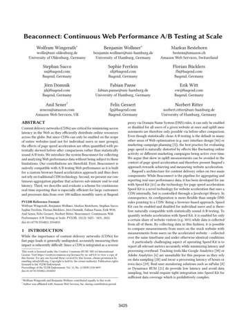
Curtis Model 1212E – July 2022Return to TOC2 — INSTALLATION, WIRING, ANDI/O CONFIGURATIONThis chapter explains how to mount and wire the controller. The chapter also describes features andbasic configuration for the inputs, outputs, and drivers.MOUNTING THE CONTROLLERTo prevent external corrosion and leakage paths, mount the controller in a location that will keepthe controller clean and dry. For ease of service, make sure the status LED is visible.The controller’s electronics are sealed to IP65. The environmental protection for the connectorsdepends upon whether sealed (IP54) or unsealed (IP40) TE Connectivity parts are used.The following diagram shows the outline and mounting hole dimensions. To mount the controller,use the two mounting holes at the opposing corners of the heatsink.135.0120.04.0 Status LED60.0M1M24X M4X0.740.0B 75.0B 2X Ø5.045.020.5Figure 2-1Mounting Dimensions2 — INSTALLATION, WIRING, AND I/O CONFIGURATIONpg. 5
Curtis Model 1212E – July 2022Return to TOCWARNINGSYou must heed the following warnings:Working on electrical systems is potentially dangerous. Protect yourself againstuncontrolled operation, high current arcs, and outgassing from lead-acid batteries:UNCONTROLLED OPERATION — Some conditions could cause the motor to run out of control.Disconnect the motor or jack up the vehicle and get the drive wheels off the ground beforeattempting any work on the motor control circuitry.CAUTIONHIGH CURRENT ARCS — Batteries can supply very high power, and arcing can occur if theyare short circuited. Always open the battery circuit before working on the motor control circuit.Wear safety glasses and use properly insulated tools to prevent shorts.LEAD-ACID BATTERIES — Charging or discharging generates hydrogen gas, which can buildup in and around the batteries. Follow the battery manufacturer’s safety recommendations.Wear safety glasses.You will need to take steps to ensure that the vehicle system’s EMC performance complieswith applicable regulations. For guidelines, see Appendix A.The controller contains ESD-sensitive components. Use appropriate precautions in connecting,disconnecting, and handling the controller.HIGH CURRENT CONNECTIONSThe controller provides four M4X0.7 terminals for high current connections:TerminalDescriptionB Positive battery inputB–Negative battery inputM1Motor phase M1M2Motor phase M2Note: Positive current flows from phase M1 to phase M2, negative current flows from phase M2 tophase M1.pg. 62 — INSTALLATION, WIRING, AND I/O CONFIGURATION
Curtis Model 1212E – July 2022Return to TOCLOW CURRENT CONNECTIONSThe low current connections are provided by two connectors, which are described in the followingtopics.8-Pin I/O Connector (J1)The following table describes the pins on the 8-pin connector (J1):PinDescriptionJ1-1CAN LJ1-2CAN HJ1-3Switch 1J1-4Charger InhibitJ1-5Switch 5J1-6I/O GroundJ1-7Switch 2J1-8Horn DriverThe connector can be sealed to IP54 or IP40, depending upon which TE Connectivity parts are used.The following table describes the part numbers:Table 2-1 Mating Connector Parts: 8-Pin ConnectorPartIP54 (Sealed Connector)IP40 (Unsealed Connector)ConnectorTYCO #794821-1, plugTYCO #770579-1, plugC
3-Wire Pot Throttle If the throttle is a 3-wire pot, the circuit provides full fault protection against open or shorted wires anywhere in the throttle pot assembly. Connect the pot to the pot high (J2-3), pot wiper (J2-6) and I/O ground (J1-6) pins. For a wiring diagram and the pot inputs' specifications, see Potentiometer Circuit.