Transcription
https://doi.org/10.5194/gmd-2020-387Preprint. Discussion started: 7 December 2020c Author(s) 2020. CC BY 4.0 License.APFoam-1.0: integrated CFD simulation of O3–NOx–VOCschemistry and pollutant dispersion in typical street canyonLuolin Wu1, Jian Hang1, Xuemei Wang2, Min Shao2, and Cheng Gong315School of Atmospheric Sciences, Sun Yat-sen University, Guangzhou 510275, P. R. ChinaInstitute for Environmental and Climate Research, Jinan University, Guangzhou 510632, P. R. China3China Aerodynamics Research and Development Center, Mianyang 621000, P. R. China2Correspondence to: Xuemei Wang (eciwxm@jnu.edu.cn) and Jian Hang (hangj3@mail.sysu.edu.cn)Abstract. Urban air quality issues are closely related to the human health and economic development. In order to improvethe resolution and numerical accuracy of urban air quality simulation, this study has developed the Atmospheric Photolysis10calculation framework (APFoam-1.0), an open-source CFD code based on OpenFOAM, which can be used to examine themicro-scale reactive pollutant formation and dispersion in the urban area. The chemistry module of the newly APFoam hasbeen modified by adding five new types of reaction, which implements the coupling with atmospheric photochemicalmechanism (full O3–NOx–VOCs chemistry) and CFD model. Additionally, numerical model has been validated and showsthe good agreement with wind tunnel experimental data, indicating that the APFoam has sufficient ability to study urban15turbulence and pollutant dispersion characteristics. By applying the APFoam, O 3–NOx–VOCs formation processes anddispersion of the reactive pollutants are analyzed in an example of typical street canyon (aspect ratio H/W 1). Chemistrymechanism comparison shows that O3 and NO2 are underestimated while NO is overestimated if the VOCs reactions are notconsidered in the simulation. Moreover, model sensitivity cases reveal that 82%–98% and 75%–90% of NO and NO2 arerelated to the local vehicle emissions which are verified as the dominated contributors to local reactive pollutant20concentration in contrast to their background conditions.Besides, a large amount of NOx emission, especially NO emission, is beneficial to reduce the O3 concentrations since NOconsumes O3. Background precursors (NOx/VOCs) from boundary conditions only contribute 2%–16% and 12%–24% ofNO and NO2 concentrations and raise O3 concentration by 5%–9%. Weaker ventilation conditions lead to accumulation ofNOx and higher NOx concentration, but a lower O3 concentrations due to the stronger NO titration effect consuming O 3.25Furthermore, in order to reduce the reactive pollutant concentrations under the odd-even license plate policy (reduce 50% ofthe total vehicle emissions), vehicle VOCs emissions should be reduced by at least another 30% to effectively lower O 3, NOand NO2 concentrations at the same time. These results indicate that the examination of the precursors (NOx/VOCs) fromboth traffic emissions and background boundaries is the key point for better understanding O 3–NOx–VOCs chemistrymechanisms in street canyons and providing effective guidelines for the joint prevention and control of local street air30pollution.1
https://doi.org/10.5194/gmd-2020-387Preprint. Discussion started: 7 December 2020c Author(s) 2020. CC BY 4.0 License.Keyword. CFD model; O3–NOx–VOCs chemistry; Urban pollution; Street canyon; OpenFOAM;1 Introduction35With the worldwide rapid urbanization, air pollution in cities, such as haze and photochemical smog characterized by highlevels of the particulate matter and/or surface ozone (O3), has become one of the widely concerned environmental problems(Lu et al., 2019; Wang et al., 2020). Recently, the observational data have shown that PM2.5, one of the major pollutants incites, has decreased 30%–50% across China due to strict air quality control measures (Zhai et al., 2019). At the same time,87%, 63%, 93%, 78% and 89% of the observational stations in China have shown the decreasing trend of CO, NO 2, SO2,40PM10 and PM2.5 in recent 5 years, respectively (Fan et al., 2020). Various data indicate that air quality in China has beensignificantly improved. Unlike other pollutants, however, O3 concentrations has increased in major urban clusters of China(Lu et al., 2018). Severe O3 pollution episodes still exist and happen frequently (Wang et al., 2017). Therefore, research onreactive pollutants such as O3, which has adverse effect on human health (Goodman et al., 2015; Liu et al., 2018b; Sousa etal., 2013), the productivity of crop (Rai and Agrawal, 2012), building materiel (Massey, 1999) and vegetation (Yue et al.,452017), is of great significance to the further improvement of air quality especially in urban area.From the perspective of the cause of urban air pollution, traffic-related emissions are the major part of airbornepollutant sources, including the precursors of O 3, NOx ( NO NO2) and volatile organic compounds (VOCs) (Degraeuweet al., 2017; Kangasniemi et al., 2019; Keyte et al., 2016; Pu and Yang, 2014; Wild et al., 2017; Wu et al., 2020). It has beenbelieved that the production of O3 is from the NO2 photolysis. Generally, in a clean atmosphere, the produced O3 would be50consumed by NO titration effect. However, with the involved VOCs, NO concentrations become lower due to theconsumption with RO2 (the production of VOCs and OH, VOCs OH RO2 H2 O), which weaken the NO titration effectand consequently lead to the O3 accumulation (Seinfeld and Pandis, 2016). In China, previous studies have shown that 22%–52% of total CO, 37%–47% of total NOx, and 24%–41% of total VOCs emissions are contributed by the vehicle emissions inurban area (Li et al., 2017; Zhang et al., 2009; Zheng et al., 2014, 2009).55To investigate the formation pattern and dispersion of reactive pollutants, numerical simulation has been considered asan effective method by using the air quality models. Based on length scales, the air flow and air quality modeling in cities arecommonly categorized into four groups by length scales, i.e., street scale ( 100 m), neighborhood scale ( 1 km), city scale( 10 km), and regional scale ( 100 km) (Britter and Hanna, 2003). With the complex geometric and non-uniformity inbuilding distribution within cities, Computational Fluid Dynamics (CFD) simulation has recently gained popularity in the60urban climate research (Toparlar et al., 2017). Different from the typical meso-scale ( 1000km) and regional-scale ( 100km)air quality models, CFD has better performance in micro-scale pollutant dispersion within the urban street canyon ( 100m)or urban neighborhoods ( 1 km), which are restricted spaces with more complicated turbulent mixing and poorer ventilationcondition than rural areas (Zhong et al., 2015). Besides the shorter physical processes in micro-scale urban models ( 100m2
https://doi.org/10.5194/gmd-2020-387Preprint. Discussion started: 7 December 2020c Author(s) 2020. CC BY 4.0 License.1km, 10s-100s), the rather fast chemical processes of NO2 photolysis and NO titration with the complex chain of VOCs65reactions also require finer resolution model (Vardoulakis et al., 2003). For instance, CFD models with fine grid ( 0.1-1m)and small timestep ( 0.1s) have been effectively adopted to simulate these high-resolution spatial and temporal variations inurban areas (Sanchez et al., 2016).With the rapid growth of the high-performance computing (HPC) platforms, computational power is no longer anobstacle. CFD simulation shows the good application prospect in urban microclimate research (Fernandez et al., 2020;70Garcia-Gasulla et al., 2020). Many previous studies have investigated the pivotal factors that affect the reactive pollutantdistribution within the street canyon by using the CFD model, such as street-building aspect ratio (He et al., 2017; Zhang etal., 2020; Zhong et al., 2015), ambient wind conditions (Kim and Baik, 2004; Kwak et al., 2013; Merah and Noureddine,2019; Tominaga and Stathopoulos, 2010), thermal effects (Baik et al., 2007; Kwak and Baik, 2014; Park et al., 2012, 2016),emissions from vehicle (Kim et al., 2012; Kwak and Baik, 2012; Liu et al., 2018a; Zhang et al., 2019b) or the photochemical75reaction mechanism (Sanchez et al., 2016; Zhong et al., 2017).Currently, most of the simulation studies have been carried out by the application of commercial CFD software. Thissoftware has rather simple operation which is effective to save time when setting up the simulation case. However, thecommercial codes are usually closed source, which is a “black box” for users (Chatzimichailidis et al., 2019). In this case,the adjustment to the equations and parameters or modifications to the model is difficult for some specific simulations.80Therefore, an open-source CFD code for atmospheric photolysis calculation, APFoam-1.0, was developed in this study.Open Source Field Operation and Manipulation (OpenFOAM) was selected as the platform for the APFoam framework, asOpenFOAM has good performance in computing scalability and low uncertainty levels which shows good ability in largescale CFD simulation with million-level grid number (Robertson et al., 2015). Additionally, the solvers in OpenFOAM forspecific CFD problem can be developed by using the appropriate packaged functionality, which simplifies the difficulty of85programming. Furthermore, OpenFOAM has been also well-developed with various pre- and post-processing utilities whichare convenient for data manipulation (OpenFOAM Foundation, 2018).This paper is organized as follows: besides this Sect. 1 of introduction, Sect. 2 presents a full description of the newchemistry module and simulation solver. Model validation for the photochemical mechanism, turbulence simulation andpollutants dispersion compared with the chemical box model and several wind tunnel experiments is discussed in Sect. 3.90Subsequently, in Sect. 4, a series of sensitive case has been set up to investigate the contribution of the key factors on thereactive pollutants in a typical street canyon (aspect ratio, building height/street width, H/W 1). Finally, the conclusion andfuture research plan for the APFoam framework are summarized in Sect. 5 and Sect. 6.2 Model description953
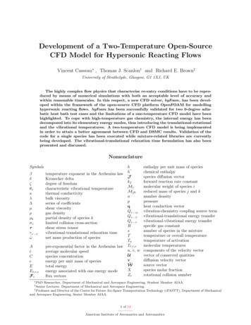
https://doi.org/10.5194/gmd-2020-387Preprint. Discussion started: 7 December 2020c Author(s) 2020. CC BY 4.0 License.2.1 General overviewAPFoam framework has been developed based on OpenFOAM which is an open-source code for CFD simulation. For thenumerical solution, APFoam uses finite volume method (FVM) to discretize the governing equations and adopts arbitrarythree-dimensional structured or unstructured meshes. All variables of the same cell are stored at the center of the control100volume (CV), and complex geometries can be easily handled with FVM (Chauchat et al., 2017). In APFoam, Laminar,Reynolds-averaged Navier–Stokes equations (RANS) and Large eddy simulation (LES) method are available for turbulencesolution. Additionally, APFoam also has complete boundary conditions to choose for numerical simulation.Based on the OpenFOAM, APFoam has been developed to conduct the photochemical simulation within theatmosphere. Different from the general chemical reaction type, there are some new types of the gaseous reactions describing105the photochemical processing. More details will be introduced in Sect. 2.2.To make it easier to get started with APFoam, the structure of the simulation case folder is consistent with theOpenFOAM. Figure 1 shows the flow diagram of simulation set-up in APFoam. The solver of APFoam, APChemFoam forone-dimension (1D) chemistry solving is modified from the solver ChemFoam which will be introduced in detail in Sect. 2.3.Other three-dimension (3D) solvers are modified from the solver reactingFoam, including APreactingFoam for online110solving coupled with flow and chemical reaction, APonlyChemReactingFoam for solving only chemical reaction with acertain flow field and APsteadyReactingFoam for online solving coupled with flow and chemical reaction in steady-state.More details will be presented in Sect. 2.4.For the simulation running (see Figure 1), mesh files, configure files and initial condition files should be preparedbefore the simulation. Mesh files can be made by various ways, such as blockMesh application executable by using data115from blockMeshDict or fluentMeshToFoam by converting the .msh file to OpenFOAM format. For APFoam simulation, allrequired configure files are also listed in Figure 1. Besides, user-defined function can be loaded at run-time withoutrecompiling the program, via writing related configuration files in the system folder. As for initial conditions, the initial stateof turbulence, environment (e.g. temperature, pressure) and chemical species are necessary for the simulation. The results ofAPFoam would contain the wind flow and pollutant concentrations, which can be processed by the Paraview in OpenFOAM120or any other CFD post-processing tools.2.2 Chemistry moduleFor photochemical calculation, there are five types of reactions in the mechanism. In the original version of OpenFOAM,these types of reactions are not included and should be added to the chemistry module prior to simulation. These types of the125reactions are described as followed:(1) Arrhenius reactions:Arrhenius reaction is the basic reaction in the mechanism, and the rate of the Arrhenius reaction is calculated as4
https://doi.org/10.5194/gmd-2020-387Preprint. Discussion started: 7 December 2020c Author(s) 2020. CC BY 4.0 License.𝑘 𝐴 (𝑇 𝐵𝐸) exp ( )300𝑇(1)where A, B and E are the parameters of the reaction rates.130(2) Photolysis reactions:Photolysis reactions are first-order reactions, and the photolysis rate is calculated as𝜆2𝑘𝑝ℎ𝑜𝑡 𝐽(𝜆) 𝑎𝑏𝑠(𝜆) 𝑄𝑌(𝜆)𝑑𝜆(2)𝜆1where kphot is the first order rate for the photolysis reaction; J (λ), abs (λ) and QY (λ) are the intensity of the light source,absorption cross section and the quantum yield for the reaction at wavelength λ, respectively.135Actually, the photolysis rate could be calculated by other photolysis rate model such as Fast-J (Wild et al., 2000), TUV(Madronich and Flocke, 1999), or obtained from photolysis data set such as IUPAC (Atkinson et al., 2003). Since thephotolysis rate does not depend on temperature, in the current version of APFoam, the reaction rates are obtained from theliterature (Carter, 2010) rather than online calculation in order to improve the calculation efficiency.140(3) Falloff reactions:Rate of Falloff reactions is a function of temperature and pressure which is calculated as𝑘(𝑇, 𝑀) where 𝑧 {1 [𝑘 (𝑇) {𝑀}log10 { 𝑘0 (𝑇) }𝑖𝑛𝑓𝑁𝑘0 (𝑇) [𝑀] 𝐹𝑧𝑘0 (𝑇) [𝑀]1 𝑘𝑖𝑛𝑓 (𝑇) }{(3)]2 } 1 ; [M] is the concentration of third body, which depends on total pressure; F is broadeningfactors. k0 and kinf are the rates of in Arrhenius form at low-pressure limit and high-pressure limit, respectively.145(4) “Three k” reactions:The rate of “Three k” reactions depends on three reaction rates in Arrhenius form. The rate is calculated as𝑘(𝑇, 𝑀) 𝑘0 (𝑇) 𝑘3 (𝑇) [𝑀] (1 𝑘3 (𝑇) [𝑀])𝑘2 (𝑇)(4)where k0, k2 and k3 are three reaction rates and [M] is the concentration of third body.(5) “Two k” reactions:The rate of “Two k” reactions depends on two reaction rates in Arrhenius form. The rate is calculated as150𝑘(𝑇, 𝑀) 𝑘1 (𝑇) 𝑘2 (𝑇) [𝑀](5)where k1 and k2 are two reaction rates and [M] is the concentration of third body.In the current version of the APFoam, two atmospheric photochemical mechanisms are included in the model, which wasSAPRC07 (Carter, 2010) and CB05 (Yarwood et al., 2005). For SAPRC07, two versions of the chemical mechanism areavailable, which are CS07A and SAPRC07TB. CS07A is one of the condensed versions of the mechanism, which contains15552 species and 173 reactions. SAPRC07TB is a more complicated version and even contains toxics species, with 141 speciesand 436 reactions. As for CB05, basic version with 51 species and 156 reactions is optional in the model.5
https://doi.org/10.5194/gmd-2020-387Preprint. Discussion started: 7 December 2020c Author(s) 2020. CC BY 4.0 License.2.3 One-dimension chemical solver (APchemFoam)In APFoam framework, one-dimension chemistry solver (i.e. chemistry box model) called APchemFoam is included in the160model. This solver only concerns the chemical concentration and reaction heat variation during simulation, and calculationsare started from initial conditions within a single cell mesh. The concentration and energy equation are described as(OpenFOAM Foundation, 2018): 𝜌𝑌𝑖 𝑤𝑖 (𝑌𝑖 , 𝑇) 𝑡ℎ 𝑢0 𝑡𝑝𝑞̇ 𝑑𝜏𝜌0 𝜌𝑝 165𝜌𝑅𝑇𝑀𝑎𝑣𝑒(6)(7)(8)where 𝑌𝑖 is the species mass fraction; 𝑤𝑖 is the reaction rate; 𝑇 is the temperature; 𝑢0 is the initial energy; 𝑝 is the pressure; 𝜌is the density; 𝑞̇ is the heat from reaction; 𝑅 is the gas constant and 𝑀𝑎𝑣𝑒 is the average molar weight.2.4 Three-dimensional (3D) CFD solver with photochemical reaction170As mentioned above, three 3D solvers for atmospheric photochemical CFD calculation, including APreactingFoam,APonlyChemReactingFoam and APSteadyReactingFoam, are developed in the APFoam framework.For APreactingFoam, flow field, chemical reaction and pollutant dispersion are solved simultaneously in this solver.Firstly, the continuity governing equation in this solver is:175 𝜌 (𝜌𝑈) 0 𝑡(9) 𝜌𝑈 (𝜌𝑈𝑈) 𝜏 𝑝 𝑡(10)Besides, the momentum governing equation is:Additionally, the energy governing equation is: 𝜌ℎ 𝜌𝐾 𝑝 𝑞̇ (𝜌𝑈ℎ) (𝜌𝑈𝐾) (𝛼𝑒𝑓𝑓 ℎ) 𝑡 𝑡 𝑡(11)Where 𝜌 is the density; 𝑈 is the velocity vector; 𝑝 is the pressure; 𝜏 is the viscous stress tensor; ℎ is the specific enthalpy; 𝐾180is the specific kinetic energy; 𝛼eff is the effective thermal diffusivity coefficient; 𝑞̇ is the heat from reaction.Pressure-velocity coupling schemes for solving the flow field is PIMPLE algorithm, a merged PISO–SIMPLEalgorithm in OpenFOAM toolkit. This algorithm uses the steady-state solution (SIMPLE algorithm) for the flow field withinthe time step. When defined tolerance criterion is reached, this algorithm uses PISO algorithm in the outer correction loopand moves on in time (Holzmann, 2017). The PIMPLE algorithm allows the larger Courant numbers (Co 1) so that time6
https://doi.org/10.5194/gmd-2020-387Preprint. Discussion started: 7 December 2020c Author(s) 2020. CC BY 4.0 License.185step can be increased to reduce the computation time. Besides, the governing equation for the reactive species transportationis: 𝜌𝑌𝑖 (𝜌𝑈𝑌𝑖 ) (𝜇 𝑌𝑖 ) [ 𝑌𝑖 ]𝑐ℎ𝑒𝑚 𝐸𝑖 𝑡(12)where 𝑌𝑖 is the concentration of species 𝑖; 𝜌 is the density; 𝑈 is the velocity vector; 𝜇 is the kinematic viscosity; [ 𝑌𝑖 ]𝑐ℎ𝑒𝑚 isthe concentration change of species 𝑖 from the chemical reaction; As mentioned above, [ 𝑌𝑖 ]𝑐ℎ𝑒𝑚 is calculated following the190equations of (6)–(8). 𝐸𝑖 is the emission source of species 𝑖.APonlyChemReactingFoam is only capable of solving the chemical reaction and species dispersion under a certain flowfield. The purpose of developing this solver is to save the computation time and reduce repetitive simulation. In general, theatmospheric chemical reactions have negligible effect on the flow field. Therefore, when the example cases to be studied donot involve the flow field change, this solver is suitable for this kind of simulation. The governing equation for the reactive195species transportation is consistent with APreactingFoam (Eq. (12)).APSteadyReactingFoam is developed for solving the chemical reaction and species dispersion under the steady-stateflow field. In this solver, pressure-velocity coupling scheme switches to SIMPLE algorithm for steady-state solution. Thecontinuity governing equation in this solver is:200 𝜌𝑈 0(13) (𝜌𝑈𝑈) 𝑝 (𝜇 𝑈)(14) (𝜌𝑈ℎ) (𝜌𝑈𝐾) (𝛼𝑒𝑓𝑓 ℎ) 𝑞̇(15)Besides, the momentum governing equation is:Also, the energy governing equation is:where 𝜌 is the density; 𝑈 is the velocity vector; 𝑝 is the pressure; 𝜇 is the kinematic viscosity; ℎ is the specific enthalpy; 𝐾 is205the specific kinetic energy; 𝛼eff is the effective thermal diffusivity coefficient; 𝑞̇ is the heat from reaction.As for reactive species, the governing equation for the transportation still applies Eq. (12) as well, in order to ensure thestability of chemical reaction.3 Model validation2103.1 Photochemical reaction mechanismTo verify the accuracy of chemical reaction solution and specie concentration calculation, APFoam results are comparedwith the results from SAPRC box modeling software (Carter, 2010). For the chemical mechanism, CS07A is selected forvalidation in this study, and simulation time is set as 24h without diurnal variation (i.e. chemical reaction rate is constantduring simulation).7
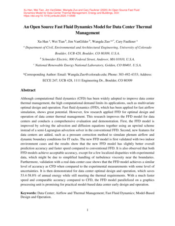
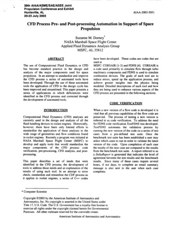
https://doi.org/10.5194/gmd-2020-387Preprint. Discussion started: 7 December 2020c Author(s) 2020. CC BY 4.0 License.215Figure 2 shows the concentrations of 52 species from two models. In general, APFoam results have a good agreementwith the SAPRC box model. Except that some species have large errors when the magnitude is very small (Figure 2f–h), thesimulation results for other species from two models are basically consistent.For further investigation, relative error (RE, %) for each specie at each time step and mean relative error (MRE, %) arecalculated for the selected species with large bias. These statistics are calculated as followed:𝑅𝐸𝑖,220𝑡 𝐶𝐴𝑃𝐹𝑜𝑎𝑚, 𝑖, 𝑡 𝐶𝑆𝐴𝑃𝑅𝐶,𝐶𝑆𝐴𝑃𝑅𝐶, 𝑖, 𝑡 𝑛𝑡 1 𝑀𝑅𝐸𝑖 where 𝑅𝐸𝑖,𝑡225𝐶𝐴𝑃𝐹𝑜𝑎𝑚, 𝑖, 𝑡 𝐶𝑆𝐴𝑃𝑅𝐶,𝐶𝑆𝐴𝑃𝑅𝐶, 𝑖, 𝑡𝑛is the relative error of specie 𝑖 at time step 𝑡; 𝐶𝐴𝑃𝐹𝑜𝑎𝑚,APFoam ; 𝐶𝑆𝐴𝑃𝑅𝐶,𝑖, 𝑡𝑖, 𝑡𝑖, 𝑡 100%𝑖, 𝑡(16) 100%(17)is the concentrations of specie 𝑖 at time step 𝑡 fromis the concentrations of specie 𝑖 at time step 𝑡 from SAPRC box model; 𝑀𝑅𝐸𝑖, is the mean relativeerror of specie 𝑖 and 𝑛 is the total number of the time step.Overall, most of the 𝑅𝐸𝑖,𝑡 are less than 1%, indicating that simulation error of APFoam is less than 1% during the wholesimulation period. However, there are 6 species with RE and MRE greater than 1%, which are TERP, ISOPRENE, OLE1,OLE2, IPRD and ARO2. The MRE of these 6 species are 44.0%, 40.7%, 7.74%, 38.5%, 7.71% and 1.20%, respectively.Additionally, Figure 3 shows time series of RE and concentrations for these high RE and MRE value species. In Figure 3a,230RE values in the early stage of simulation (t 0–180 min) are less than 1% for these species. However, the REs of TERP,ISOPRENE and OLE2 increase dramatically after t 180 min. The REs can even up to respective 190.4%, 297.0% and867.4% in the following simulation. It should be noted that, at the later time, the REs of these 3 species have no valuesbecause they are consumed up during the chemical reaction and their concentrations from SARPC box model become zero.The significant increase in the RE values of OLE1 and IPRD begins at t 1020 min, with the maximum RE values of 60.1%235and 60.9%, respectively. Relatively, the RE of ARO2 is smaller with the value of 5.0% only.Figure 3b illustrates the concentrations variation of these 6 species with worst agreement from two models. It can befound that the concentrations of these 6 species keep dropping during the whole simulation period. Combined with the resultof Figure 3a, the dramatical increase of RE is due to the significant concentration decrease of these 6 species. In this studycase, these 6 species are continuously consumed without complementation, which results in the concentrations of these240species tending to be 0. For extremely small number, the processing of different model is diverse. Thus, when the reductionof magnitude excesses 10-5 to 10-6, the RE would become much larger between two models. In the realistic situation, theconcentrations of the species would not be completely consumed up with continuous emission source and boundaryconditions. Therefore, the photochemical reaction simulation results of APFoam could be reliable and the overall errorsmight be less than 1%.2458
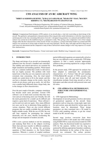
https://doi.org/10.5194/gmd-2020-387Preprint. Discussion started: 7 December 2020c Author(s) 2020. CC BY 4.0 License.3.2 Numerical settings and validation study in urban flow modellingIt is well known that large eddy simulations (LES) perform more accurately in simulating urban turbulent characteristicsthan the Reynolds-Averaged Navier-Stokes (RANS). However, RANS models (e.g., k-ε models) are still more widelyutilized because of the disadvantages of LES, such as the much more computational time and resource requirements, the250difficulties in setting appropriate wall boundary conditions and defining the time-dependent domain inlet, the challenges todevelop advanced sub-grid scale models. Among the RANS turbulence models (Tominaga and Stathopoulos, 2013; Yoshieet al., 2007), in contrast to the modified k-ε models (e.g. realizable and RNG k-ε models), although the standard k-ε modelperforms worse in predicting turbulence in the strong wind region of urban districts (e.g. separate flows near building corner),the prediction accuracy is better in simulating the low-wind-speed region (e.g. weak wind in 2D street canyon sheltered by255buildings at both sides). Hence, as one of the widely adopted RANS methods, the standard k-ε model is selected to solve theincompressible steady-state turbulent flows in 2D street canyon.The governing equations are as below :̅ 0 𝑈(18)1̅𝑈̅) ((𝜇 𝜇𝑡 ) 𝑈̅) 𝑝̅ (𝑈𝜌(19)𝜇𝑡) 𝑘) 𝑃𝑘 𝜌𝜀𝜎𝑘(20)𝜇𝑡𝜀𝜀2) ε) 𝐶𝜀1 𝑃𝑘 𝐶𝜀2 𝜌𝜎𝜀𝑘𝑘(21)̅𝜌𝑘) ((𝜇 (𝑈260̅ 𝜌𝜀) ((𝜇 (U̅ is the time-average velocity vector; 𝑝̅ is the time-average pressure; 𝜇 is the kinematic viscosity; 𝜇𝑡where 𝜌 is the density; 𝑈is the kinematic eddy viscosity (𝜇𝑡 𝜌𝐶𝜇𝑘2𝜀̅̅̅̅′ ′ 𝑢𝑗 ); 𝐶 , 𝐶 ,̅̅̅̅̅̅, 𝐶𝜇 0.09); 𝑃𝑘 is the turbulence production term (𝑃𝑘 𝜌𝑢𝑖 𝑢𝑗𝜀1𝜀2 𝑥𝑖𝜎𝑘 and 𝜎𝜀 are constant as 1.44, 1.92, 1.0 and 1.3, respectively.To further evaluate the numerical accuracy of the turbulence flow simulation, a scaled CFD case is performed under the265estimation of wind tunnel data. In the wind tunnel experiments (Figure 4a), 25 rows of building model in total are set alongthe wind direction with the working section of 11 m long, 3 m wide and 1.5 m tall. For each row, building height (H),building width (B) and street width (W) are 12 cm, 5 cm and 5 cm (i.e. aspect ratio H/W 2.4), respectively. The span-wise(or lateral) length is L 1.25 m 10H which is sufficient long to ensure the 2D flow characteristics in the street canyon(Hang et al., 2020; Oke, 1988; Zhang et al., 2019a), i.e. the flow in the targeted street region is determined by the external270flow above it but with little impacts from the lateral boundaries. Free flow wind speed in the wind tunnel experiment is 13m/s, corresponding to the reference 𝑅𝑒 number (𝑅𝑒 𝑈𝑟𝑒𝑓 𝐻𝜐) in order of 105.Figure 4b and 4c show the schematic diagrams of the CFD simulation domain setting for a single full-scale streetcanyon simulation. H and W of the street canyon are 24 m and 10 m, with spatial scale ratio of 200:1 compared with thewind tunnel experiment. Besides, the building width B and Ly in the CFD simulation are 10 m and 3.2 m (2H/15),9
https://doi.org/10.5194/gmd-2020-387Preprint. Discussion started: 7 December 2020c Author(s) 2020. CC BY 4.0 License.275respectively, assuming that only a section (Ly 2H/15) of long street canyons adopted with symmetry conditions is applied attwo lateral boundaries. The minimum grid size in this case is 0.2 m with expansion ratio of 1.2 from the wall surface towardthe surrounding, which refers to the grid independence tests from our previous research (Zhang et al., 2019a). The upstreamdomain inlet profiles along Line E and comparison of profiles along Line F (Figure 4c) are measured by the Laser DopplerAnemometry (LDA) System in wind tunnel tests. Additionally, CFD inlet profiles of stream-wise velocity (u) and turbulent280kinetic energy (TKE) are fitted following the profiles in experimental data (Figure 5).All governing equations for the flow and turbulent quantities are discretized by FVM and SIMPLE scheme is used forthe pressure and velocity coupling. The under-relaxation factors for pressure term, momentum term, k and ε terms are 0.3,0.7, 0.8 and 0.8 respectively. CFD simulations do not stop until all residuals become constant. Typical residuals atconvergence are 1 10 6, 1 10 9 and 1 10 6 for Ux, Uy and Uz, respectively, 1 10 7 for continuity, 1 10 6 for k, and 1 28510 6 forε.Figure 6 shows the stream-wise velocity profiles of simulation results and experimental data along the centerline (LineF) of the street canyon. The predicted wind profile agrees well with the wind tunnel data. One main vortex structure isformed in the street canyon. The center of the main velocity (i.e. stream-wise velocity is 0) also matches well betweensimulation and experiment.290Furthermore, some statistical parameters, including normalized mean square error (NMSE), fractional bias (FB) andcorrelation coefficient (R) are calculated by the following equations:𝑁𝑀𝑆𝐸 𝑛𝑖 1(𝑂𝑖 𝑃𝑖 )2 𝑛𝑖 1 𝑂𝑖 𝑃𝑖2(𝑂̅ 𝑃̅ )𝑂̅ 𝑃̅𝑛 𝑖 1[(𝑂𝑖 𝑂̅)(𝑃𝑖 𝑃̅ )]𝑅 𝑛[ 𝑖 1(𝑂𝑖 𝑂̅)2 ]0.5 [ 𝑛𝑖 1(𝑃𝑖 𝑃̅ )2 ]0.5𝐹𝐵 295(22)(23)(24)where 𝑛 is the total number of measurement points; 𝑂𝑖 is the experimental data at measurement point 𝑖; 𝑃𝑖 is the CFD resultsat measurement point 𝑖; 𝑂̅ is the mean value of experimental data at all points; 𝑃̅ is the mean value of CFD results at allpoints. According to the pervious works (Sanchez et al., 2016), the model acceptance criteria for urban configuration areNMSE 1.5, 0.3 FB 0.3 and R 0.8. In this simulation case, the respective NMSE, FB and R are 0.06, -0.13 and 0.95(Table 1), which shows the good performance of the APFoam in 2D pollutant dispersion simulation.3003.3 Pollutant dispersion in 2D street canyonThe pollutant dispersion accuracy in 2D street canyon is validated by wind tunnel experimental data (Meroney et al., 1996).The wind tunnel, also the CFD domain configuration is presented in Figure 7. 28 rows of the wooden bar with 27 street10
https://doi.org/10.5194/gmd-2020-387Preprint.
Open Source Field Operation and Manipulation (OpenFOAM) was selected as the platform for the APFoam framework , as OpenFOAM has good performance in computing scalability and low uncertainty levels which shows good ability in large - scale CFD simulation with million -level grid number (Robertson et al., 2015 ).