Transcription
REPORT OF GEOTECHNICAL INVESTIGATIONSH 5 OVER NORTH FORK OF THE RED RIVER OVERFLOW BRIDGETILLMAN COUNTY, OKLAHOMA29516(04)PROJECT NO. 16092INTRODUCTION. 1GENERAL . 1PROPOSED CONSTRUCTION . 1SCOPE OF WORK . 2FIELD AND LABORATORY INVESTIGATIONS . 3FIELD EXPLORATION . 3LABORATORY TESTING . 5SITE DESCRIPTION. 6SURFACE CONDITIONS . 6SITE GEOLOGY . 7SUBSURFACE CONDITIONS . 8GROUNDWATER CONDITIONS . 9SOLUBLE SULFATES . 10INTERNATIONAL BUILDING CODE (IBC) SITE CLASSIFICATION . 10ENVIRONMENTAL CONSIDERATIONS . 11CLOSURE. 12APPENDICESAPPENDIX A – Field InvestigationAPPENDIX B – Laboratory ResultsAPPENDIX C – General Notes
REPORT OF GEOTECHNICAL INVESTIGATIONSH 5 OVER NORTH FORK OF THE RED RIVER OVERFLOW BRIDGETILLMAN COUNTY, OKLAHOMA29516(04)PROJECT NO. 16092INTRODUCTIONGeneralThis report presents the results of the geotechnical investigation performed for theproposed replacement of the existing five span bridge along SH 5 over the North Fork ofthe Red River Overflow. The bridge is located approximately 3.5 miles west of Tiptonnear the Jackson County Line in Tillman County, Oklahoma. The purpose of thisinvestigation is to evaluate the subsurface conditions at the site and to provideinformation pertaining to the geotechnical aspects of the proposed project.Proposed ConstructionThe project will include the replacement of the existing five span bridge with a new triplespan bridge along an offset alignment approximately 50 feet south of the existingalignment. The new bridge will have a clear roadway width of 40 feet, which isapproximately 12 feet wider than the existing bridge. The length of the new bridge willbe 270 feet, which is approximately 145 feet longer than the existing bridge.
SH 5 over N Fork of the Red River Overflow - Tillman Co.29516(04)RRC Project No. 16092December 2, 2016Scope of WorkThe scope of this investigation includes the following:1. Review of previous geotechnical and geological information of sites near thissite. This was augmented with data obtained during the field investigationphase of the project.2. Investigation of the subsurface soils by drilling and testing a total of 4boreholes within the planned project area3. A laboratory testing program consisting of moisture content, Atterberg limits,sieve analysis and soluble sulfate testing on the overburden soilsencountered and chloride ion, sulfate ion and pH testing on the surface andgroundwater encountered4. International Building Code (IBC) site classification for seismic design5. Additional considerations for sustainable design and construction2
SH 5 over N Fork of the Red River Overflow - Tillman Co.29516(04)RRC Project No. 16092December 2, 2016FIELD AND LABORATORY INVESTIGATIONSField ExplorationSubsurface exploration was performed on November 2 and 3, 2016. The borings werelocated in the field by a representative of Red Rock Consulting by measuring distancesfrom known site reference points as depicted on boring location plans provided by SRB.The locations of the borings should be considered accurate only to the degree implied bythe methods used to define them.The subsurface exploration program consisted of drilling 4 borings under the full timesupervision of an engineer. One boring was drilled at each of the proposed abutmentand pier locations. The boring locations were proposed by SRB. All borings, exceptboring B-1, was drilled approximately at the proposed locations. Boring B-1 was movedapproximately 20 feet north of the proposed location due to underground utilities and afence. The borings are shown on the boring location diagram, which is included inAppendix A.Borings B-1 and B-2 were advanced 30 feet into bedrock. Borings B-3 and B-4 wereadvanced 35.5 and 37.5 feet into bedrock, respectively, due to a very soft layerencountered within the bedrock of these two borings.The borings were advanced using wet rotary drilling methods from an all-terrain vehicle(ATV) mounted CME-75 drill rig and a truck mounted CME-55 drill rig. Both rigs wereequipped with an automatic hammer. Samples of the overburden were obtained in theborings as per Oklahoma Department of Transportation (ODOT) specifications.Representative samples of the overburden materials were obtained by split-barrelsampling procedures (Standard Penetration Test, SPT) in general accordance withASTM Specifications D-1586. After SPT refusal was attained, the hardness of thebedrock was evaluated in all of the borings using Texas Cone Penetrometer (TCP) inaccordance with the AASHTO Manual on Subsurface Investigation and as modified bythe Oklahoma Department Transportation.The SPT test uses a standard, 2-inch outside diameter, split-barrel sampling spoon thatis driven into the bottom of the boring with a 140 pound automatic drive hammer thatfalls 30 inches. The blows per foot, N, is the number of hammer blows required toadvance the sampling spoon the last 12 inches, or less, of an 18-inch sampling interval.The N value is used to estimate the in-situ relative density of granular soils, theconsistency of cohesive soils, and the hardness of weathered bedrock.3
SH 5 over N Fork of the Red River Overflow - Tillman Co.29516(04)RRC Project No. 16092December 2, 2016Drilling equipment and methods have evolved considerably over the past 65 yearsfollowing the development of the first SPT empirical design correlations. As a result, theautomatic drive hammers on modern geotechnical drilling rigs must be calibrated forefficiency. The efficiency of an automatic drive hammer is specific to each hammer andis expressed by an energy efficiency ratio. The energy efficiency ratio is calculated bydividing the actual measured energy delivered to the drill rod by the theoretical energydelivered by a 140 pound automatic drive hammer that falls 30 inches. The hammerefficiency can be used to convert a SPT value into an N value with a nominal 60 percentefficiency, the N60 value. The N60 value is rarely used in engineering practice, but iswidely considered to be more accurate and more representative of the N values used todevelop the original SPT empirical design correlations. Both the N and N60 values arepresented on the boring logs in Appendix A.The TCP test is a standard test developed by the Texas Highway Department toevaluate the consistency or hardness of the bedrock material. The TCP test drives apenetrometer cone into the bedrock material with a 140 pound automatic drive hammerthat falls 30 inches. The TCP is driven for a series of blows, the first 10 being seatingblows, followed by two 50 blow counts. After 50 blows of the automatic hammer, thedistance the TCP has advanced is measured and recorded. The distance the TCP isdriven is used to estimate the hardness of bedrock.Water samples were obtained from the overflow and from borings B-3 and B-4 at adepth approximately 10 feet below the groundwater table.After performing SPT tests, TCP tests and collecting water samples, the holes werebackfilled with grout and cuttings as required by the Oklahoma State Statutes forGeotechnical drilling.Samples were collected and transported back to the lab for further classification andtesting. The final boring logs were developed from the draft logs, observations and testresults of the samples returned to the laboratory. The stratigraphic contacts indicatedare only for the specific dates and locations reported, and therefore, are not necessarilyrepresentative of other locations and times. The boring logs, presenting conditionsencountered at each location explored, are included in Appendix A.4
SH 5 over N Fork of the Red River Overflow - Tillman Co.29516(04)RRC Project No. 16092December 2, 2016Laboratory TestingRepresentative soil samples were tested to refine the field classifications and to evaluatephysical properties of the soils which may affect the geotechnical aspects of projectdesign and construction.The soil laboratory testing program included the following: Moisture content (ASTM D2216)Liquid and plastic limit (ASTM D4318)Full sieve (ASTM D422)Soluble sulfate (OHD L-49)The water laboratory testing program included the following: Chloride ion (EPA 300)Sulfate ion (EPA 300)pH (SM 4500-H B)The results of the soil laboratory tests conducted are shown on the boring logs inAppendix A and are also included in Appendix B. The results of the water laboratorytests conducted are included in Appendix B.5
SH 5 over N Fork of the Red River Overflow - Tillman Co.29516(04)RRC Project No. 16092December 2, 2016SITE DESCRIPTIONSurface ConditionsAt the time of the field investigation, an existing five span bridge was located along SH 5over the North Fork of the Red River Overflow in Tillman County, Oklahoma. SH 5 wasa two lane asphalt paved undivided highway in the area of the overflow bridge. Theoverflow bridge was approximately 125 feet long and had two 12-foot-wide driving lanes.There was riprap on the abutment slopes. The main channel bridge was locatedapproximately 550 feet west of the overflow bridge.Guard rail was not observed in any sides of the overflow bridge. The approach roadwayon both sides of the bridge had nearly flat side slopes.The North Fork of the Red River overflow was dry in the area of the bridge during drillingactivities. A pond was located approximately 70 feet south of the bridge along theoverflow channel. The pond appeared to have been made by damming up the overflowchannel. The overflow channel banks were moderately steep.The boring locations were covered with grass and were dry at the time of drilling. TheATV and truck mounted drill rigs did not experience difficulty maneuvering around thesite.Survey data was collected from the project site by using differential leveling proceduresto determine the surface elevations of the borings. The southwest bridge seat of theoverflow bridge, which was located approximately at station 387 00, 35’ left of theconstruction reference line (CRL), was used as a benchmark. According to existingbridge plans the benchmark had an elevation of 1255.5 feet. Based on this benchmarkthe elevations of the borings ranged from 1246.1 to 1256.2 feet.The approximate elevation at each boring location is shown on the boring locationdiagram and on the boring logs in Appendix A.6
SH 5 over N Fork of the Red River Overflow - Tillman Co.29516(04)RRC Project No. 16092December 2, 2016Site GeologyThe geology of the project site was researched using the “Division Five EngineeringClassification of Geological Materials”, published by the Oklahoma Department ofTransportation (ODOT) and the Geologic Map of the “Hydrologic Atlas 6 of Oklahoma,Reconnaissance of the Water Resources of The Lawton quadrangles, southwesternOklahoma,” by John H. Havens, published by the U.S. Geological Survey, 1977.The ODOT publication indicates the project site is located over Alluvium (Qal) underlainby the Hennessey Unit (Phy). The geologic deposit and formation are described thereinas follows:Alluvium consists of sand, silt, clay, gravel and/or combinations of materials.Alluvium is found along the flood plains (bottom land) of streams and is normally presentat places along all streams.The Hennessey Unit consists dominantly of reddish-brown, blocky clay shalesand mudstones with minor amounts of sandstones and siltstones. Much of theshale is massive and breaks with sharp-edged conchoidal fractures. Numerous bandsor streaks of white or light green color are common in the shales. These bands varyfrom a few inches to 4 feet in thickness. Soft, buff sandstones are present locally nearthe base of the unit. The total thickness of the unit is about 200 feet.In Division 5, the Hennessey Unit outcrops over extensive areas of Kiowa, Greer,Tillman, and eastern Jackson Counties. Here, the unit overlies much of the foldedgeologic units of the Wichita Mountains Uplift. Within 6 to 10 miles of the WichitaMountains, the strata of the Hennessey and underlying Addington Units are gradationalinto the conglomerates of the Post Oak Unit, as is the case in eastern Kiowa County.The topography of the unit varies from nearly level prairies and cultivated areas to nearlybarren gullies which resemble badland topography. Mesquite trees and sparce grasscover are common in the badland area.According to the USGS geologic map, the project site is underlain by Alluvium (Qal)underlain by the Hennessey Group (Phy). The geologic deposit and formation aredescribed therein as follows:Alluvium consists of sand, clay and gravel as much as 50 feet thick.The Hennessey Group consists of reddish-brown to gray shale with some tansandstones, 130 to 200 feet thick.7
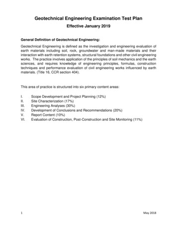
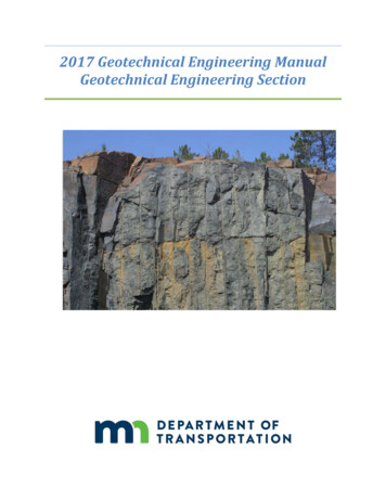
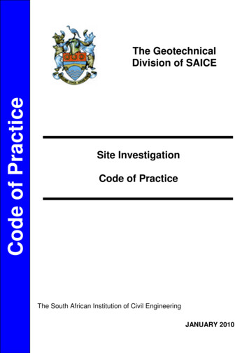
SH 5 over N Fork of the Red River Overflow - Tillman Co.29516(04)RRC Project No. 16092December 2, 2016Subsurface ConditionsInformation collected during the field investigation indicates that the overburden primarilyconsisted of sand with various amounts of gravel, silt and lean clay that extended fromthe surface to the top of bedrock. The overburden in the top approximate 7, 17 and 8feet of borings B-1, B-2 and B-4, respectively, appeared to be fill materials. Theoverburden in boring B-3 appeared to be native to the site. Bedrock ranged between 11and 27 feet in the borings. The approximate depths to bedrock and boring terminationdepths are summarized in Table 1.Table 1 – Bedrock and Boring Termination 9.6B-422.51233.3601195.8The bedrock in the borings consisted of very soft to very hard shale. The bedrockextended to the boring termination depths. Boring termination depths in the boringsranged between 46.5 and 60 feet, which was equal to 30 to 37.5 feet into bedrock.A Texas Cone Penetrometer (TCP) test failed in borings B-3 and B-4 at a depth of 11.5and 28 feet, respectively. A failed TCP test is indicative of a very soft layer at that depth.The failed TCP tests resulted in boring termination depths greater than 30 foot into rockin these borings.All borings were cased with hollow stem augers from the surface to bedrock to avoidsloughing of the cohesionless soil and gravel. Subsurface conditions are described ingreater detail on the boring logs in Appendix A.8
SH 5 over N Fork of the Red River Overflow - Tillman Co.29516(04)RRC Project No. 16092December 2, 2016Groundwater ConditionsGroundwater conditions were monitored in the borings during and following completionof drilling operations. The approximate groundwater levels and cave-in depths aresummarized in Table 2.Table 2 – Groundwater Levels and Cave-In DepthsApproximate Groundwater LevelsBoringWhile DrillingCave In DepthsAfter 1241.8171239.2*The boring caved in above the groundwater levelThe groundwater levels encountered during drilling are likely more accurate since thewater levels were measured while casing the borings with auger. The groundwatermeasured in boring B-1 shortly after drilling operations may not be precise due to thenature of wet rotary drilling. Boring B-2 was dry after a delay of 0.5 hours because itcaved in above the groundwater level.To obtain accurate groundwater level information, long-term observations in a well orpiezometer that is sealed from the influence of surface water would be needed.Fluctuations in groundwater levels can occur due to seasonal variations in the amount ofrainfall, runoff, altered drainage paths, and other factors not evident at the time boringswere advanced. Consequently, the contractor should be aware of this possibility whileconstructing this project.Water testing was performed on the surface and ground water samples collected fromthe project site. The surface sample was collected from the pond located along theoverflow channel. The groundwater samples were collected from borings B-3 and B-4 ata depth approximately 10 feet below the groundwater table. The samples were testedfor chlorides, sulfates and pH levels. Water testing results are included in Appendix B.9
SH 5 over N Fork of the Red River Overflow - Tillman Co.29516(04)RRC Project No. 16092December 2, 2016Soluble SulfatesSulfates are naturally occurring in some soils and water. Concrete members in contactwith sulfate bearing soils and water are vulnerable to sulfate attack. The sulfates in thesoil and/or water could potentially react with the calcium and aluminum in the concrete toform expansive minerals in the hardened concrete. A reaction of this type would likelycause cracking and degradation of the concrete.Based on the soluble sulfate test results, the maximum soluble sulfate level encounteredin the soils was less than 200 ppm and the maximum dissolved sulfate encountered inthe water was 702 mg/l or 702 ppm. As per the American Concrete Institute (ACI) 31811 Building Code Requirements for Structural Concrete and Commentary (2011) Table4.2.1, the project site is categorized in S1 (moderate) exposure class.The ACI 318-11 Building Code Table 4.3.1 provides the following requirements for S1exposure class: Maximum water to cement ratio in the concrete mix design should be of 0.50 Minimum compressive strength of the concrete should be 4000 psi Moderate sulfate resistant (Type II) cement should be used. Other types ofPortland cements with C3A contents up to 10 percent are permitted if the water tocement ratio does not exceed 0.4.Any material imported to the site during construction should be tested for solublesulfates. Soluble sulfate levels are shown on the laboratory test results in Appendix B.International Building Code (IBC) Site ClassificationFrom the geotechnical investigation and subsequent laboratory tests, the onsite soilsyield a Site Class “D”. This site class is based on average standard penetrationresistance (SPT) procedure, a maximum boring depth of 60 feet and the assumption thatthe bedrock encountered in the borings is consistent and extends to at least 100 feet.This site class does not take into account induced ground movements, such asthe recent earthquakes due to injection wells. To obtain a more accurate site classmore extensive testing must be used to evaluate the subsurface conditions.10
SH 5 over N Fork of the Red River Overflow - Tillman Co.29516(04)RRC Project No. 16092December 2, 2016ENVIRONMENTAL CONSIDERATIONSThe environmental effect of construction projects is a growing concern in our industry.Some points for consideration of the environment regarding site construction andconstruction materials are summarized in the following paragraphs. These points shouldbe incorporated into the design and construction of this project for a moreenvironmentally friendly result. The following is only a summary. For a more in-depthdiscussion on sustainable design and construction, please contact Red Rock Consulting.Site ConstructionSEDIMENTATION AND EROSION CONTROLReduce pollution from construction activities by controlling soil erosion, waterwaysedimentation, and airborne dust generation. This can be accomplished most efficientlyby using seeding or mulching and silt fence. Seeding or Mulching – If the excavated site is left open for an extended amountof time, soil erosion should be retarded by using seeding or mulching to coverand hold the soils.Silt Fence – Prevent sedimentation of receiving streams by constructing silt fence(posts with a filter fabric media) around the project site. The silt fence is used toremove sediment from storm water that may runoff the construction site.Construction MaterialsLOCAL MATERIALSIncrease the demand for building materials and products that are extracted andmanufactured within the region, thereby supporting the use of indigenous resources andreducing the environmental impacts resulting from transportation of materials. Examplesof local materials that could be considered in the construction of this project includewater, recycled steel, concrete and/or aggregate and sand.RECYCLED MATERIALSReuse building materials and products in order to reduce demand for virgin materialsand to reduce waste, thereby reducing impacts associated with the extraction andprocessing of virgin resources. Examples of recycled materials that could be consideredin the construction of this project include recycled steel piles, concrete and aggregate.11
SH 5 over N Fork of the Red River Overflow - Tillman Co.29516(04)RRC Project No. 16092December 2, 2016CLOSUREThe data presented in this report are based on the negotiated scope for this project andsite conditions as they existed at the time of the field exploration. The conditionsencountered in the exploratory borings are representative subsurface conditions withinthe study area.This report was prepared for the exclusive use of SRB, ODOT and their agents andconsultants. It should be made available to prospective contractors for information andfactual data only and not as a warranty of subsurface conditions similar to thoseinterpreted from the boring logs or discussions presented herein.12
APPENDIX A
BORING NUMBER B-17042 Highwater Circle, Suite BEdmond, Oklahoma, 73003405-562-3328PAGE 1 OF 2CLIENT SRBPROJECT NAME SH 5 North Fork of Red River O'flow Bridge; 29516(04)PROJECT NUMBER 16092PROJECT LOCATION Tillman County, OKCOMPLETED 11/3/16DRILLING CONTRACTOR DSO - Drilling Services of OklahomaGROUND ELEVATION 1256.2 ftSTATION 386 00 OFFSET 1' rightGROUND WATER LEVELS:DRILLING METHOD wet rotary - CME 55 TruckDURING DRILLING 15.0 ft / Elev 1241.2 ftLOGGED BY RAG1 hrs AFTER DRILLING 12.0 ft / Elev 1244.2 55MOISTURECONTENT (%)MATERIAL DESCRIPTIONSILTY SAND, dark brown (7.5YR 3/4) and black (7.5YR 2.5/1)*possible fill material*1256.2'POORLY GRADED SAND with SILT, light reddish brown(2.5YR 6/3), loose*possible fill material*1252.2'LEAN CLAY, dark brown (7.5YR 3/4)1249.2'SILTY SAND, light reddish brown (2.5YR 6/3), medium dense1247.2'1245ATTERBERGLIMITSBLOW COUNTSNGRAPHICLOGDEPTH (ft)ELEVATION (ft)Cave In Depth 12.0 ft / Elev 1244.2 ftSPT8400NP9.8SPT111100NP22.3SAMPLE TYPECHECKED BY TDBNOTES west abutment boring; auger cased to 25 feetPASSING #200SIEVE (%)DATE STARTED 11/3/16151240POORLY GRADED SAND, very pale brown (10YR 7/3),medium dense1241.2'SPT181600NP3.1POORLY GRADED SAND with SILT and GRAVEL,very pale brown (10YR 7/3), medium dense1236.2'SPT171400NP5.5LEAN CLAY, shaley, red (2.5YR 4/6) with light bluish gray (GLEY2 7/1), 1233.2'hard1232.2'SHALE, red (2.5YR 4/6) with light bluish gray (GLEY2 7/1),very soft to very hardSPT1636181898.8201235251 DURING AFTER CAVE IN 16092 LOGS.GPJ DATA TEMPLATE.GDT 12/2/161230301225351220401215451210(Continued Next Page)1927TC 0/1"50/1"TC50/0.5"50/0.3"
BORING NUMBER B-17042 Highwater Circle, Suite BEdmond, Oklahoma, 511601155SHALE, red (2.5YR 4/6) with light bluish gray (GLEY2 7/1),very soft to very hard (continued)1232.2'Boring Termination Depth 54.5 feetBoring Completed and Grouted on ING #200SIEVE DLIMITMOISTURECONTENT (%)MATERIAL DESCRIPTIONBLOW COUNTSNSAMPLE TYPEGRAPHICLOGPROJECT LOCATION Tillman County, OKDEPTH (ft)PROJECT NAME SH 5 North Fork of Red River O'flow Bridge; 29516(04)PROJECT NUMBER 16092ELEVATION (ft)CLIENT SRB12051 DURING AFTER CAVE IN 16092 LOGS.GPJ DATA TEMPLATE.GDT 12/2/16PAGE 2 OF 2
BORING NUMBER B-27042 Highwater Circle, Suite BEdmond, Oklahoma, 73003405-562-3328PAGE 1 OF 2CLIENT SRBPROJECT NAME SH 5 North Fork of Red River O'flow Bridge; 29516(04)PROJECT NUMBER 16092PROJECT LOCATION Tillman County, OKCOMPLETED 11/3/16DRILLING CONTRACTOR DSO - Drilling Services of OklahomaGROUND ELEVATION 1255.9 ftSTATION 386 90 OFFSET 20' leftGROUND WATER LEVELS:DRILLING METHOD wet rotary - CME 75 ATVDURING DRILLING 17.0 ft / Elev 1238.9 ftLOGGED BY RAG0.5 hrs AFTER DRILLING noneCHECKED BY TDBCave In Depth 13.5 ft / Elev 1242.4 ftLIQUIDLIMITPLASTICLIMITPLASTICITYINDEXSILTY SAND , dark brown(7.5YR 3/4) and black (7.5YR 2.5/1), very loose to dense*possible fill material consisting of asphalt debris and gravel*MOISTURECONTENT (%)01255BLOW COUNTSNMATERIAL 637191895.9SAMPLE TYPEGRAPHICLOGDEPTH (ft)ELEVATION (ft)NOTES pier 1 boring; auger cased to 27 feetPASSING #200SIEVE (%)DATE STARTED 11/3/1651250101245151240POORLY GRADED SAND, very pale brown (10YR 7/3), loose1238.9'201235251 DURING AFTER CAVE IN 16092 LOGS.GPJ DATA TEMPLATE.GDT 12/2/161230LEAN CLAY, shaley, red (2.5YR 4/6) with light bluish gray (GLEY2 7/1), 1232.4'hardSHALE, red (2.5YR 4/6) with light bluish gray (GLEY2 7/1),soft to very hard301228.9'SPT 50/5"TC ontinued Next Page)
BORING NUMBER B-27042 Highwater Circle, Suite BEdmond, Oklahoma, 73003405-562-3328501205SHALE, red (2.5YR 4/6) with light bluish gray (GLEY2 7/1),soft to very hard (continued)1228.9'TC50/1.1"50/0.8"551200Boring Termination Depth 57.5 feetBoring Completed and Grouted on 11/3/1611951190118511801 DURING AFTER CAVE IN 16092 LOGS.GPJ DATA TEMPLATE.GDT 12/2/16117511701165116011551198.4'TC LIMITSLIQUIDLIMITMOISTURECONTENT (%)MATERIAL DESCRIPTIONBLOW COUNTSNSAMPLE TYPEGRAPHICLOGPROJECT LOCATION Tillman County, OKDEPTH (ft)PROJECT NAME SH 5 North Fork of Red River O'flow Bridge; 29516(04)PROJECT NUMBER 16092ELEVATION (ft)CLIENT SRBPASSING #200SIEVE (%)PAGE 2 OF 2
BORING NUMBER B-37042 Highwater Circle, Suite BEdmond, Oklahoma, 73003405-562-3328PAGE 1 OF 1CLIENT SRBPROJECT NAME SH 5 North Fork of Red River O'flow Bridge; 29516(04)PROJECT NUMBER 16092PROJECT LOCATION Tillman County, OKDATE STARTED 11/2/16COMPLETED 11/2/16DRILLING CONTRACTOR DSO - Drilling Services of OklahomaGROUND ELEVATION 1246.1 ftSTATION 387 80 OFFSET 20' rightGROUND WATER LEVELS:DRILLING METHOD wet rotary - CME 75 ATVDURING DRILLING 6.0 ft / Elev 1240.1 ftLOGGED BY RAG18 hrs AFTER DRILLING 3.5 ft / Elev 1242.6 ftCHECKED BY TDBCave In Depth 4.5 ft / Elev 1241.6 ftMOISTURECONTENT 21145.4POORLY GRADED SAND with SILT, very pale brown(10YR 7/3), medium dense1241.1'SPT112300NP6.1LEAN CLAY, shaley, red (2.5YR 4/6) with light bluish gray (GLEY2 7/1), 1235.6'stiff to hard1235.1'1234.6'SHALE, red (2.5YR 4/6) with light bluish gray (GLEY2 7/1),very soft to very hard*Failed Texas Cone at approximately 11.5 feet*SPT1330141692.6PASSING #200SIEVE (%)BLOW COUNTSN1246.1'MATERIAL DESCRIPTION01245ATTERBERGLIMITSCLAYEY SAND, dark reddish brown (2.5YR 3/3), looseSAMPLE TYPEGRAPHICLOGDEPTH (ft)ELEVATION (ft)NOTES pier 2 boring; auger cased to 15 feet5124010123515310TC .5"TC50/3.8"50/3.1"TC50/0.9"50/0.4"201225251 DURING AFTER CAVE IN 16092 LOGS.GPJ DATA TEMPLATE.GDT 12/2/161220301215351210TC 1"451200Boring Termination Depth 46.5 feetBoring Completed on 11/2/16 and Grouted on 11/3/161199.6'
BORING NUMBER B-47042 Highwater Circle, Suite BEdmond, Oklahoma, 73003405-562-3328PAGE 1 OF 2CLIENT SRBPROJECT NAME SH 5 North Fork of Red River O'flow Bridge; 29516(04)PROJECT NUMBER 16092PROJECT LOCATION Tillman County, OKCOMPLETED 11/3/16DRILLING CONTRACTOR DSO - Drilling Services of OklahomaGROUND ELEVATION 1255.8 ftGROUND WATER LEVELS:DRILLING METHOD wet rotary - CME 75 ATVDURING DRILLING 15.0 ft / Elev 1240.8 ftLOGGED BY RAG17 hrs AFTER DRILLING 14.0 ft / Elev 1241.8 STICLIMIT123510LIQUIDLIMIT124005MOISTURECONTENT (%)1245MATERIAL DESCRIPTIONLEAN CLAY with SAND, very dark brown (7.5YR 2.5/2)*possible fill material*SILTY SAND, brown (7.5YR 5/2) to dark reddish brown(2.5YR 3/3) to very dark brown (7.5YR 2.5/2) and black (7.5YR 2.5/1),loose*possible fill material*1255.8'1255.3'SILTY SAND, brown (7.5YR 5/2) to dark reddish brown(2.5YR 3/3) to very dark brown (7.5YR 2.5/2) and black (7.5YR 2.5/1),loose to medium dense1247.8'ATTERBERGLIMITSBLOW COUNTSN1250DEPTH (ft)ELEVATION (ft)1255Cave In Depth 12.0 ft / Elev 1243.8 00NP34.6SPT401330161487.017361
1. Review of previous geotechnical and geological information of sites near this site. This was augmented with data obtained during the field investigation phase of the project. 2. Investigation of the subsurface soils by drilling and testing a total of 4 boreholes within the planned project area 3.