Transcription
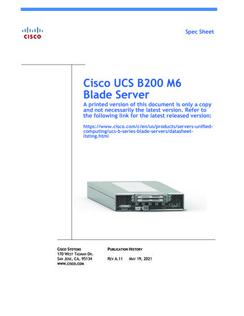
Spec SheetCisco UCS B200 M6Blade ServerA printed version of this document is only a copyand not necessarily the latest version. Refer tothe following link for the latest released atasheetlisting.htmlCISCO SYSTEMS170 WEST TASMAN DR.SAN JOSE, CA, 95134WWW.CISCO.COMPUBLICATION HISTORYREV A.11MAY 19, 2021
OVERVIEW . . . . . . . . . . . . . . . . . . . . . . . . . . . . . . . . . . . . . . . . . . . . . . . 3DETAILED VIEWS . . . . . . . . . . . . . . . . . . . . . . . . . . . . . . . . . . . . . . . . . . . 4Blade Server Front View . . . . . . . . . . . . . . . . . . . . . . . . . . . . . . . . . . . . . . . . . . . . . . .4BASE SERVER STANDARD CAPABILITIES and FEATURES . . . . . . . . . . . . . . . . . 5CONFIGURING the SERVER . . . . . . . . . . . . . . . . . . . . . . . . . . . . . . . . . . . . 7STEP 1 CHOOSE BASE SERVER SKU . . . . . . . . . . . . . . . . . . . . . . . . . . . . . . . . . . . . . . . 8STEP 2 CHOOSE CPU(S) . . . . . . . . . . . . . . . . . . . . . . . . . . . . . . . . . . . . . . . . . . . . . . 9STEP 3 CHOOSE MEMORY . . . . . . . . . . . . . . . . . . . . . . . . . . . . . . . . . . . . . . . . . . . . 12Memory Configurations, Features, and Modes . . . . . . . . . . . . . . . . . . . . . . . . . . . . . . . . 14STEP 4 CHOOSE MLOM REAR MEZZANINE ADAPTER . . . . . . . . . . . . . . . . . . . . . . . . . . . . 20STEP 5 CHOOSE OPTIONAL REAR MEZZANINE ADAPTERS (VIC or Port Expander) . . . . . . . . 22STEP 6 CHOOSE OPTIONAL FRONT MEZZANINE ADAPTER . . . . . . . . . . . . . . . . . . . . . . . . 23STEP 7 CHOOSE OPTIONAL DRIVES . . . . . . . . . . . . . . . . . . . . . . . . . . . . . . . . . . . . . . 24STEP 8 CHOOSE TRUSTED PLATFORM MODULE . . . . . . . . . . . . . . . . . . . . . . . . . . . . . . 28STEP 9 CHOOSE UCSM SOFTWARE . . . . . . . . . . . . . . . . . . . . . . . . . . . . . . . . . . . . . . 29STEP 10 CHOOSE OPERATING SYSTEM AND VALUE-ADDED SOFTWARE . . . . . . . . . . . . . . . 30STEP 11 CHOOSE OPTIONAL RECOVERY MEDIA . . . . . . . . . . . . . . . . . . . . . . . . . . . . . . 34STEP 12 CHOOSE SERVICE and SUPPORT LEVEL . . . . . . . . . . . . . . . . . . . . . . . . . . . . . . 35Unified Computing Warranty, No Contract . . . . . . . . . . . . . . . . . . . . . . . . . . . . . . . . . . 35Smart Net Total Care (SNTC) for Cisco UCS . . . . . . . . . . . . . . . . . . . . . . . . . . . . . . . . . . 35Smart Net Total Care for Cisco UCS Onsite Troubleshooting Service . . . . . . . . . . . . . . . . . 37Solution Support for UCS . . . . . . . . . . . . . . . . . . . . . . . . . . . . . . . . . . . . . . . . . . . . . . 38Smart Net Total Care for UCS Hardware Only Service . . . . . . . . . . . . . . . . . . . . . . . . . . . 39Partner Support Service for UCS . . . . . . . . . . . . . . . . . . . . . . . . . . . . . . . . . . . . . . . . . 40PSS for UCS Hardware Only . . . . . . . . . . . . . . . . . . . . . . . . . . . . . . . . . . . . . . . . . . . . 41Unified Computing Combined Support Service . . . . . . . . . . . . . . . . . . . . . . . . . . . . . . . . 42UCS Drive Retention Service . . . . . . . . . . . . . . . . . . . . . . . . . . . . . . . . . . . . . . . . . . . 43Local Language Technical Support for UCS . . . . . . . . . . . . . . . . . . . . . . . . . . . . . . . . . . 43SUPPLEMENTAL MATERIAL . . . . . . . . . . . . . . . . . . . . . . . . . . . . . . . . . . . 44System Board . . . . . . . . . . . . . . . . . . . . . . . . . . . . . . . . . . . . . . . . . . . . . . . . . . . . . 44Memory Configuration and Mirroring . . . . . . . . . . . . . . . . . . . . . . . . . . . . . . . . . . . . . . 45Memory Mirroring . . . . . . . . . . . . . . . . . . . . . . . . . . . . . . . . . . . . . . . . . . . . . . 47Memory Support for 3rd Generation Intel Xeon Scalable Processors (Ice Lake) . . . . . . . . 48PMEM Support . . . . . . . . . . . . . . . . . . . . . . . . . . . . . . . . . . . . . . . . . . . . . . . . . 48App Direct Mode . . . . . . . . . . . . . . . . . . . . . . . . . . . . . . . . . . . . . . . . . . . . . . . 48Memory Mode . . . . . . . . . . . . . . . . . . . . . . . . . . . . . . . . . . . . . . . . . . . . . . . . . 48SPARE PARTS . . . . . . . . . . . . . . . . . . . . . . . . . . . . . . . . . . . . . . . . . . . .UPGRADING or REPLACING CPUs . . . . . . . . . . . . . . . . . . . . . . . . . . . . . . .UPGRADING or REPLACING MEMORY . . . . . . . . . . . . . . . . . . . . . . . . . . . . .TECHNICAL SPECIFICATIONS . . . . . . . . . . . . . . . . . . . . . . . . . . . . . . . . . .49555658Dimensions and Weight . . . . . . . . . . . . . . . . . . . . . . . . . . . . . . . . . . . . . . . . . . . . . . . 58Power Specifications . . . . . . . . . . . . . . . . . . . . . . . . . . . . . . . . . . . . . . . . . . . . . . . . 581Cisco UCS B200 M6 Blade Server
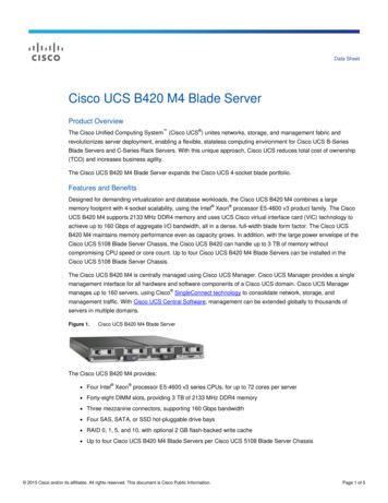
OVERVIEWOVERVIEWDelivering performance, versatility and density without compromise, the Cisco UCS B200 M6 Blade Serveraddresses the broadest set of workloads, from IT and web infrastructure through distributed database.The enterprise-class Cisco UCS B200 M6 blade server extends the capabilities of Cisco’s Unified ComputingSystem portfolio in a half-width blade form factor. The Cisco UCS B200 M6 harnesses the power of the latest3rd Gen Intel Xeon Scalable Processors (Ice Lake) with: Up to 4 TB of RAM per CPU (using 16 x 256 GB DRAMs) or up to 6 TB per CPU (using 8 x 256 GB DRAMsand 8 x 512 GB Intel Optane Persistent Memory Modules (PMEMs)) Two solid-state drives (SSDs), or Two PCIE NVMe drives, or Mini storage carrier with M.2 SATA drives Up to 80 Gbps throughput connectivity.The B200 M6 server is the follow-on server to the popular B200 M5 server and includes support for thefollowing: 3rd Gen Intel Xeon Scalable Processors (Ice Lake). Up to 256 GB 3200-MHz DDR4 memory DIMMs1. Up to 8 TB total memory (for 2 CPUs) is available if the memory slots are all populated with 32 x 256GB DDR4 DIMMs or 12 GB total memory if the memory slots are populated with 16 x 256 GB DDR4 DIMMsand 16 x 512 GB PMEMs. Front mezzanine daughter card options 12G RAID controller module with two 2.5-inch SAS/SATA SSD drives, or Pass-through module with two 2.5-inch PCIe NVMe drives, or Mini storage carrier with up to four M.2 SATA drivesFigure 1 Cisco UCS B200 M6 Blade ServerNotes1. Available in Q4 of CY 2021Cisco UCS B200 M6 Blade Server3
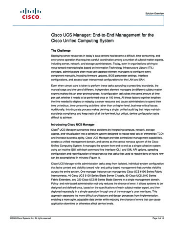
DETAILED VIEWSDETAILED VIEWSBlade Server Front ViewFigure 2 is a detailed front view of the Cisco UCS B200 M6 Blade Server.Figure 2 Blade Server Front View123456781Asset pull tagEach server has a plastic tag that pullsout of the front panel. The tag containsthe server serial number as well as theproduct ID (PID) and version ID (VID). Thetag also allows you to add your own assettracking label without interfering withthe intended air flow.6Drive Bay 2(shown unpopulated)2Console connector17Power button and LED3Ejector thumbscrew8Network link status LED4Blade ejector handle9Blade health LED5Drive bay 1 (shown populated)10Locate button and LED9 10Notes:1. A KVM I/O cable plugs into the console connector, and can be ordered as a spare. The KVM I/Ocable in included with every Cisco UCS 5100 Series blade server chassis accessory kit.4Cisco UCS B200 M6 Blade Server
BASE SERVER STANDARD CAPABILITIES and FEATURESBASE SERVER STANDARD CAPABILITIES and FEATURESTable 1 lists the capabilities and features of the base server. Details about how to configure the server fora listed feature or capability (for example, number of processors, disk drives, or amount of memory) areprovided in CONFIGURING the SERVER on page 7Table 1 Capabilities and FeaturesCapability/FeatureDescriptionChassisThe UCS B200 M6 Blade Server mounts in a Cisco UCS 5108 Series bladeserver chassis or UCS Mini blade server chassis.CPUOne or two 3rd Gen Intel Xeon Scalable Processors (Ice Lake). Also notethat the B200 M6 Blade Server BIOS inherently enables support for IntelAdvanced Encryption Standard New Instructions (AES-NI) and does not havean option to disable this feature.ChipsetIntel C621 series chipset (Lewisburg)Memory 32 total DIMM slots Support for Advanced ECC Support for registered ECC DIMMs (RDIMMs) Support for load-reduced DIMMs (LR DIMMs) Support for PMEMs Up to 8 TB GB DDR4 DIMM memory capacity (32 x 256 GB DIMMs) Up to 12 TB memory with a mix of DIMMs and PMEMs 16 x 256 GB DIMMs, and 16 x 512 GB PMEMsModular LOMOne modular LOM (mLOM) connector at the rear of the blade for a CiscomLOM VIC adapter, which provides Ethernet or Fibre Channel over Ethernet(FCoE) connectivityCisco UCS B200 M6 Blade Server5
BASE SERVER STANDARD CAPABILITIES and FEATURESTable 1 Capabilities and Features (continued)Capability/FeatureDescriptionMezzanine Adapters(Rear)One rear mezzanine connector forMezzanine Adapters(Front)Storage controllerStorage devices Cisco Mezzanine VIC Adapter, or Cisco Mezzanine Port ExpanderOne front mezzanine connector for Cisco FlexStorage 12G RAID controller with two SAS/SATA SSD drives, or Cisco FlexStorage NVMe pass-through module with two drives, or Mini storage carrier with up to four M.2 SATA drivesFor the front mezzanine connector: Cisco FlexStorage 12G RAID controller module with drive bays Cisco FlexStorage NVMe pass-through module with drive baysTwo front facing drive bays with choice of: Up to two 2.5” SFF solid-state drives up to 7.6 TB capacity each Up to two 2.5” PCIe NVMe drives up to 6.4 TB capacity each VideoUp to two mini storage carriers, each with either two 240 GB or 960 GBM.2 SATA drivesThe Cisco Integrated Management Controller (CIMC) provides video using aMatrox G200e video/graphics controller. Integrated 2D graphics core with hardware accelerationDDR4 memory interface supports up to 512 MB of addressable memory(8 MB is allocated by default to video memory) Supports display resolutions up to 1920 x 1200 32 bpp@ 60Hz Single lane PCI-Express host interface running at Gen 2 speedInterfacesOne KVM console connector on the front panelPower subsystemIntegrated in the Cisco UCS 5108 blade server chassisFansIntegrated in the Cisco UCS 5108 blade server chassis.Integrated managementprocessorThe built-in Cisco Integrated Management Controller (CIMC) GUI or CLIinterface enables monitoring of server inventory, health, and system eventlogsACPIAdvanced Configuration and Power Interface (ACPI) 4.0 Standard Supported.UCSMUCS Manager (UCSM) 4.2(1) or later runs in the Fabric Interconnect andautomatically discovers and provisions some of the server components.CIMCCisco Integrated Management Controller 4.2(1) or later6Cisco UCS B200 M6 Blade Server
CONFIGURING the SERVERCONFIGURING the SERVERFollow these steps to configure the Cisco UCS B200 M6 Blade Server: STEP 1 CHOOSE BASE SERVER SKU, page 8 STEP 2 CHOOSE CPU(S), page 9 STEP 3 CHOOSE MEMORY, page 12 STEP 4 CHOOSE MLOM REAR MEZZANINE ADAPTER, page 20 STEP 5 CHOOSE OPTIONAL REAR MEZZANINE ADAPTERS (VIC or Port Expander), page 22 STEP 6 CHOOSE OPTIONAL FRONT MEZZANINE ADAPTER, page 23 STEP 7 CHOOSE OPTIONAL DRIVES, page 24 STEP 8 CHOOSE TRUSTED PLATFORM MODULE, page 28 STEP 9 CHOOSE UCSM SOFTWARE, page 29 STEP 10 CHOOSE OPERATING SYSTEM AND VALUE-ADDED SOFTWARE, page 30 STEP 11 CHOOSE OPTIONAL RECOVERY MEDIA, page 34Cisco UCS B200 M6 Blade Server7
CONFIGURING the SERVERSTEP 1CHOOSE BASE SERVER SKUVerify the product ID (PID) of the server as shown in Table 2.Table 2 PID of the Base UCS B200 M6 Blade ServerProduct ID (PID)DescriptionUCS-M6-MLBUCS M6 Rack, Blade, Chassis MLBThis major line bundle (MLB) consists of the Blade Server (UCSB-B200-M6) withsoftware PIDs. Use this PID to begin a new configuration.UCSB-B200-M61UCS B200 M6 Blade Server without CPU, memory, drive bays, drives, VIC adapter,or mezzanine adapters (ordered as a blade chassis option)UCSB-B200-M6-U1UCS B200 M6 Blade Server without CPU, memory, drive bays, drives, VIC adapter,or mezzanine adapters (ordered standalone)Notes:1. This product may not be purchased outside of the approved bundles (must be ordered under theMLB)A base Cisco UCS B200 M6 blade server ordered in Table 2 does not include any components oroptions. They must be selected during product ordering.Please follow the steps on the following pages to order components such as the following, whichare required in a functional blade: CPUs Memory Cisco FlexStorage RAID controller with drive bays for SAS or SATA SSDs (or blank, for no localdrive support) Cisco FlexStorage pass-through module with drive bays for PCIe NVMe drives) SSD, PCIe, or SATA M.2 drives Cisco adapters (such as the VIC 1440, VIC 1480, Port Expander)8Cisco UCS B200 M6 Blade Server
CONFIGURING the SERVERSTEP 2CHOOSE CPU(S)The standard CPU features are: 3rd Gen Intel Xeon Scalable Processors (Ice Lake) Intel C621 series chipset Cache size of up to 60 MB Up to 40 coresSelect CPUsThe available CPUs are listed in Table 3. See Table 4 on page 10 for CPU suffix notations.Table 3 Available CPUsClockFreq(GHz)Power (W)CacheSize 3333333at 11.2at 11.2at 11.2at 11.2at 11.2at 11.2at 11.2at 63543.020539183 at 11.23200UCS-CPU-I63482.623542283 at 816323 at 11.23 at 302.02.22.02.320516520520548424248322828323 at 11.23 at 11.23 at 11.203200266629333200Product ID (PID)8000 Series 8352VUCS-CPU-I8352SUCS-CPU-I8351N26000 Series ProcessorsUCS-CPU-I6314U3UPI1 Links(GT/s)Highest DDR4DIMM ClockSupport (MHz)Notes:1. UPI Ultra Path Interconnect.2. The maximum number of UCS-CPU-I8351N CPUs is one3. The maximum number of UCS-CPU-I6314U CPUs is oneCisco UCS B200 M6 Blade Server9
CONFIGURING the SERVERTable 4 CPU SuffixesCPU ized for use in networking applications like L3forwarding, 5G UPF, OVS DPDK, VPP FIB router, VPP IPsec,web server/NGINX, vEPC, vBNG, and vCMTS. SKUs havehigher base frequency with lower TDPs to enable bestperformance/WattPCloud OptimizedSKU specifically designed for cloud IaaS environments todeliver higher frequencies at constrained TDPsVCloud OptimizedSKUs specifically designed for cloud environments todeliver high rack density and maximize VM/cores perTCO THigh T caseSKUs designed for Network Environment-Building System(NEBS) environmentsU1-socket OptimizedOptimized for targeted platforms adequately served bythe cores, memory bandwidth and IO capacity availablefrom a single processorSMax SGX enclavesizeSupports Max SGX enclave size (512GB) to enhance andprotect the most sensitive portions of a workload orserviceMMedia and AIoptimizedMedia, AI and HPC Segment Optimized for lower TDP &higher frequencies delivering better perf/wYSpeed Select –Performance ProfileIntel Speed Select Technology provides the ability to seta guaranteed base frequency for a specific number ofcores, and assign this performance profile to a specificapplication/workload to guarantee performancerequirements. It also provides the ability to configuresettings during runtime and provide additional frequencyprofile configuration opportunities.Supported Configurations(1) DIMM only configurations: Select one or two identical CPUs listed in Table 3 on page 9(2) DIMM/PMEM Mixed Configurations: You must select two identical CPUs listed in Table 3 on page 9(3) Configurations with NVMe PCIe drives: You must select two identical CPUs listed in Table 3 on page 9(4) One-CPU Configuration— Choose one CPU from any one of the rows of Table 3 Available CPUs, page 910Cisco UCS B200 M6 Blade Server
CONFIGURING the SERVER(5) Two-CPU Configuration— Choose two identical CPUs from any one of the rows of Table 3 Available CPUs, page 9NOTE: You cannot have two I8351N or two I6314U CPUs in a two-CPU configuration.NOTE: If you configure a server with one I8351N CPU or one I6314U CPU you cannotlater upgrade to a 2-CPU system with two of these CPUs.Caveats The selection of 1 or 2 CPUs depends on the desired server functionality. See the followingsections:—STEP 3 CHOOSE MEMORY, page 12—STEP 7 CHOOSE OPTIONAL DRIVES, page 24CAUTION: In Table 5, systems configured with the processors shown mustadhere to the ambient inlet temperature thresholds specified. If not, afan fault or executing workloads with extensive use of heavy instructionssets such as Intel Advanced Vector Extensions 512 (Intel AVX-512) mayassert thermal and/or performance faults with an associated eventrecorded in the System Event Log (SEL). Table 5 describes theconfiguration restrictions to ensure proper cooling and avoid excessiveprocessor throttling, which may impact system performance.Table 5 Ambient Temperature and Configuration RestrictionsProcessor ThermalDesign Power (TDP)CPU Product ID (PID)BladeSlotAmbientConfiguration RestrictionsTemperature LimitAnyAnyAny27 oC (80.6 oF)NoneAnyUCS-CPU-I6314UAny27 oC (80.6 oF)Limited to single processorconfigurationsUCS-CPU-I8351NCisco UCS B200 M6 Blade Server11
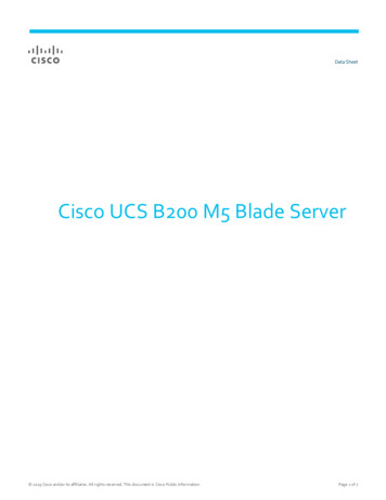
CONFIGURING the SERVERSTEP 3CHOOSE MEMORYThe available memory for the B200 M6 is as follows: Clock speed: 3200 MHz Ranks per DIMM: 1, 2, 4, or 8 Operational voltage: 1.2 V Registered ECC DDR4 DIMMS (RDIMMs), Load-reduced DIMMs (LRDIMMs), or Intel OptaneTMPersistent Memory Modules (PMEMs).Memory is organized with eight memory channels per CPU, with up to two DIMMs per channel, asshown in Figure 3.Slot 1Slot 2Slot 2Slot 1Figure 3 B200 M6 Memory OrganizationA1A2A2A1Chan AB1Chan AB2Chan BC1D1C2D2Chan CChan CChan DChan DF1G1H1E1F2F1G2G1H2H1Chan FChan GH2Chan HE2Chan EG2Chan GC1CPU 2F2Chan FC2D2 D1E2Chan EB1Chan BCPU 1E1B2Chan H8 memory channels per CPU,up to 2 DIMMs per channel32 DIMMS total (16 per CPU)8 TB maximum memory (with 256 GB DIMMs)Note: 256 GB DIMMs available in Q4 of 202112Cisco UCS B200 M6 Blade Server
CONFIGURING the SERVERChoose DIMMs and Memory MirroringSelect the memory configuration and whether or not you want the memory mirroring option.The supported memory DIMMs, PMEMs, PMEM Memory Modes, and the mirroring option are listedin Table 6. The 128 GB LRDIMM is non-3DS and the 256 GB LRDIMM is 3DSTable 6 Available DDR4 DIMMs and PMEMsPID DescriptionVoltageRanks/DIMMUCS-MR-X16G1RW16GB RDIMM SRx4 3200 (8Gb)1.2 V1UCS-MR-X32G2RW32 GB RDIMM DRx4 3200 (8Gb)1.2 V2UCS-MR-X64G2RW64 GB RDIMM DRx4 3200 (16Gb)1.2 V2UCS-ML-128G4RW128 GB LRDIMM QRx4 3200 (16Gb) (non-3DS)1.2 V4UCS-ML-256G8RW1256 GB LRDIMM 8Rx4 3200 (16Gb) (3DS)1.2 V8Product ID (PID)DIMMsIntel OptaneTM Persistent Memory ProductUCS-MP-128GS-B0Intel OptaneTM Persistent Memory, 128GB, 3200 MHzUCS-MP-256GS-B0Intel OptaneTM Persistent Memory, 256GB, 3200 MHzUCS-MP-512GS-B0Intel OptaneTM Persistent Memory, 512GB, 3200 MHzDIMM Blank2UCS-DIMM-BLKUCS DIMM BlankIntel Optane Persistent Memory (PMEM) Operational ModesUCS-DCPMM-ADApp Direct ModeUCS-DCPMM-MMMemory ModeMemory Mirroring Option3N01-MMIRRORMemory mirroring optionNotes:1. Available in Q4 of CY 20212. Any empty DIM M slot must be populated with a DIMM blank to maintain proper cooling airflow.3. For Memory Configuration and Mirroring, please refer to Memory Configuration and Mirroring on page45 and Memory Support for 3rd Generation Intel Xeon Scalable Processors (Ice Lake) onpage 48.Cisco UCS B200 M6 Blade Server13
CONFIGURING the SERVERMemory Configurations, Features, and ModesSystem speed is dependent on the CPU DIMM speed support. Refer to Available CPUs on page 9for DIMM speeds. 14The server supports the following memory reliability, availability, and serviceability (RAS)BIOS options (only one option can be chosen):—Adaptive Double Device Data Correction (ADDDC) (default)—Maximum performance—Full mirroring—Partial mirroringFor best performance, observe the following:—When one DIMM is used, it must be populated in DIMM slot 1 (farthest away from theCPU) of a given channel.—When single- or dual-rank DIMMs are populated in two DIMMs per channel (2DPC)configurations, always populate the higher number rank DIMM first (starting fromthe farthest slot). For a 2DPC example, first populate with dual-rank DIMMs in DIMMslot 1. Then populate single-rank DIMMs in DIMM 2 slot. DIMMs for CPU 1 and CPU 2 (when populated) must always be configured identically. Cisco memory from previous generation servers (DDR3 and DDR4) is not compatible with theUCS B200 M6 Blade. Memory can be configured in any number of DIMMs as pairs, although for optimalperformance, refer to the C220/C240/B200 M6 Memory Guide. For additional information, refer to Memory Configuration and Mirroring on page 45. For detailed Intel Optane Persistent Memory (PMEM) configurations, refer to the CiscoUCS B200 M6 Server Installation Guide.Cisco UCS B200 M6 Blade Server
CONFIGURING the SERVERApproved ConfigurationsNOTE: Memory mirroring is allowed only with DIMMs; no memory mirroring can beconfigured is PMEMs are installed.(1) 1-CPU configuration without memory mirroring: Select from 1 to 16 DIMMs.—1, 2, 4, 6, 8, 12, or 16 DIMMs allowed—3, 5, 7, 9, 10, 11, 13, 14, 15 DIMMs not allowed—DIMMs for both CPUs must be configured identically.The DIMMs will be placed by the factory as shown in the following table.#DIMMsCPU 1 DIMM Placement in Channels (for identically ranked DIMMs)124681216(A1)(A1, E1)(A1, C1); (E1, G1)(A1, C1); (D1, E1); (G1, H1)(A1, C1); (D1, E1); (G1, H1); (B1, F1)(A1, C1); (D1, E1); (G1, H1); (A2, C2); (D2, E2); (G2, H2)(A1, B1); (C1, D1); (E1, F1); (G1, H1); (A2, B2); (C2, D2); (E2, F2); (G2, H2)(2) 1-CPU configuration with memory mirroring: Select 2, 4, 8, 12, or 16 DIMMs per CPU (DIMMs for all CPUs must be configured identically).In addition, the memory mirroring option (N01-MMIRROR) as shown in Table 6 on page 13must be selected.The DIMMs will be placed by the factory as shown in the following table.# DIMMsPer CPUCPU 1 DIMM Placement in Channels (for identical ranked DIMMs)2(A1, E1)4(A1, C1); (E1, G1)8(A1, C1); (D1, E1); (G1, H1); (B1, F1)12(A1, C1); (D1, E1); (G1, H1); (A2, C2); (D2, E2); (G2, H2)16(A1, B1); (C1, D1); (E1, F1); (G1, H1); (A2, B2); (C2, D2); (E2, F2); (G2, H2) Select the memory mirroring option (N01-MMIRROR) as shown in Table 6 on page 13.Cisco UCS B200 M6 Blade Server15
CONFIGURING the SERVER(3) 2-CPU configuration without memory mirroring: Select from 1 to 16 DIMMs per CPU.—1, 2, 4, 6, 8, 12, or 16 DIMMs allowed—3, 5, 7, 9, 10, 11, 13, 14, 15 DIMMs not allowed—DIMMs for both CPUs must be configured identically.The DIMMs will be placed by the factory as shown in the following tables.CPU 1 DIMM Placement in Channels (foridentically ranked DIMMs)#DIMMsCPU 2 DIMM Placement in Channels (foridentically ranked DIMMs)1(A1)(A1)2(A1, E1)(A1, E1)4(A1, C1); (E1, G1)(A1, C1); (E1, G1)6(A1, C1); (D1, E1); (G1, H1)(A1, C1); (D1, E1); (G1, H1)8(A1, C1); (D1, E1); (G1, H1); (B1, F1)(A1, C1); (D1, E1); (G1, H1); (B1, F1)12(A1, C1); (D1, E1); (G1, H1); (A2, C2); (D2,E2); (G2, H2)(A1, C1); (D1, E1); (G1, H1); (A2, C2); (D2,E2); (G2, H2)16(A1, B1); (C1, D1); (E1, F1); (G1, H1); (A2,B2); (C2, D2); (E2, F2); (G2, H2)(A1, B1); (C1, D1); (E1, F1); (G1, H1); (A2,B2); (C2, D2); (E2, F2); (G2, H2)(4) 2-CPU configuration with memory mirroring: Select 2, 4, 8, 12, or 16 DIMMs per CPU (DIMMs for all CPUs must be configured identically).In addition, the memory mirroring option (N01-MMIRROR) as shown in Table 6 on page 13must be selected.The DIMMs will be placed by the factory as shown in the following tables.# DIMMsPer CPUCPU 1 DIMM Placement in Channels (foridentical ranked DIMMs)2(A1, E1)(A1, E1)4(A1, C1); (E1, G1)(A1, C1); (E1, G1)8(A1, C1); (D1, E1); (G1, H1); (B1, F1)(A1, C1); (D1, E1); (G1, H1); (B1, F1)12(A1, C1); (D1, E1); (G1, H1); (A2, C2); (D2,E2); (G2, H2)(A1, C1); (D1, E1); (G1, H1); (A2, C2); (D2,E2); (G2, H2)16(A1, B1); (C1, D1); (E1, F1); (G1, H1); (A2,B2); (C2, D2); (E2, F2); (G2, H2)(A1, B1); (C1, D1); (E1, F1); (G1, H1); (A2,B2); (C2, D2); (E2, F2); (G2, H2)16CPU 2 DIMM Placement in Channels (foridentically ranked DIMMs)Cisco UCS B200 M6 Blade Server
CONFIGURING the SERVER Select the memory mirroring option (N01-MMIRROR) as shown in Table 6 on page 13.NOTE: System performance is optimized when the DIMM type and quantity are equalfor both CPUs, and when all channels are filled equally across the CPUs in the server.Table 7 3200-MHz DIMM Memory Speeds with Different Intel Xeon Ice Lake ProcessorsDIMM and CPUFrequencies DPC(MHz)LRDIMM(8Rx4)256 GB(MHz)LRDIMM(4Rx4)128 GB(MHz)LRDIMM(4Rx4) 64 GB(MHz)RDIMMRDIMMRDIMM(2Rx4) (2Rx4) (1Rx4) 64 GB (MHz) 32 GB (MHz) 16 GB (MHz)1.2 V1.2 V1.2 V1.2 V1.2 V1.2 VDIMM 3200CPU 0032003200DIMM 3200CPU 3329332933DIMM 3200CPU 6626662666DIMM Rules Allowed DIMM count for 1 CPU: Minimum DIMM count 1; Maximum DIMM count 16 1, 2, 4, 6, 8, 12, or 16 DIMMs allowed 3, 5, 7. 9, 10, 11, 13, 14, or 15 DIMMs not allowed.Allowed DIMM count for 2 CPUs Minimum DIMM count 2; Maximum DIMM count 32 2, 4, 8, 12, 16, 24, or 32 DIMMs allowed 6, 10, 14, 18, 20, 22, 26, 28, or 30 DIMMs not allowed.DIMM Mixing: LRDIMMs cannot be mixed with RDIMMs. Single-rank DIMMs can be mixed with dual-rank DIMMs in the same channel RDIMMs can be mixed with RDIMMs, and LRDIMMs can be mixed with LRDIMMs, but mixing ofnon-3DS and 3DS RDIMMs is not allowed in the same channel, across different channels, oracross different sockets.Cisco UCS B200 M6 Blade Server17
CONFIGURING the SERVERNOTE: The 128 GB LRDIMM is non-3DS and the 256GB LRDIMM is 3DS, so these twoLRDIMMs cannot be mixed. Allowed mixing has be in pairs of similar quantities (for example, 8x32GB and 8x64GB,8x16GB and 8x64GB, 8x32GB and 8x64GB, or 8x16GB and 8x32GB). Mixing of 10x32GB and6x64GB, for example, is not allowed.NOTE: DIMM mixing is not allowed when PMEMs are installed; if PMEMs are installed,all DIMMs must be the same type and size.18Cisco UCS B200 M6 Blade Server
CONFIGURING the SERVERSee Table 8 for PMEM memory modes. See Table 8 for allowed DIMM/PMEM mixed configurations.Table 8 Intel OptaneTM Persistent Memory ModesIntel OptaneTM Persistent Memory ModesApp Direct ModePMEM operates as a solid-state disk storage device. Data is saved and isnon-volatile. Both DCPMM and DIMM capacities count towards the CPUcapacity limit.PMEM operates as a 100% memory module. Data is volatile and DRAM actsas a cache for PMEMs. Only the PMEM capacity counts towards the CPUcapacity limit). This is the factory default mode.Memory ModeTable 9 3rd Gen Intel Xeon Scalable Processors (Ice Lake) Allowable Mixed DIMM/PMEM1 PhysicalConfiguration (per socket)DIMM PMEMCountCPU 1 or CPU 2ICX: IMC2ICX: IMC3ICX: IMC1ICX: IMC0Chan 0 (F)Chan 1 (E)Chan 0 (HChan 1 (G)Chan 0 (C)Chan 1 (D)Chan 0 (A)Chan 1 ot2Slot2Slot2Slot1Slot14 42PMEMDIMMPMEMDIMMDIMMPMEM8 13DIMMDIMMDIMMDIMMDIMMDIMM8 44DIMMDIMMPMEMDIMMDIMMPMEMPMEM DIMM8 85DIMM PMEM DIMMPMEMDIMMPMEM DIMMPMEMPMEM DIMM DIMMPMEMDIMMPMEMDIMMNOTE: AD App Direct Mode, MM Memory ModeNotes:1.2.3.4.5.All systems must be fully populated with two CPUs when using PMEMs at this time.AD, MMADAD, MMAD, MMFor detailed Intel PMEM configurations, refer to the Cisco UCS B200 M6 Server Installation andService Guide.Cisco UCS B200 M6 Server Installation and Service GuideFor detailed DIMM/PMEM informations, refer the UCS C220/C240/B200 M6 Memory Guide.Cisco UCS C220/C240/B200 M6 Memory GuideCisco UCS B200 M6 Blade Server19
CONFIGURING the SERVERSTEP 4CHOOSE MLOM REAR MEZZANINE ADAPTERThe UCS B200 M6 must be ordered with a Cisco VIC mLOM Adapter. The adapter can operate in asingle-CPU or dual-CPU configuration. Table 11 shows available mLOM adapter choices.Table 10 mLOM AdaptersProduct ID (PID)DescriptionConnectorUCSB-MLOM-40G-04Cisco UCS VIC 1440 modular LOM for blade serversmLOMTable 11 Aggregate Bandwidth with mLOM Only configurationmLOMFabric Interconnects SupportedFabrics Extenders in UCS 5108 bladechassis aggregate bandwidth (Gb/s)2x 2408 2x 2304 332-16UP 64542x6410820Yes(20 Gbps)YesYesYesYesCisco developed the 1400 Series Virtual Interface Card (VIC) to provide flexibility to createmultiple NIC and HBA devices.The VIC features are listed here: Includes enhancements, including network overlay offload support. Provides two Converged Network Adapter (CNA) ports, supporting both Ethernet and FCoE Delivers up to 80 Gbps total I/O throughput to the server Supports 2x40 (native) Gbps Unified I/O ports Supports up to 256 fully functional unique and independent PCIe adapters and interfaces Provides virtual machine visibility from the physical network and a consistent networkoperations model for physical and virtual servers Supports customer requirements for a wide range of operating systems and hypervisorsThe mLOM VIC on the UCS B200 M6 enables connectivity to the Fabric Interconnect eitherthrough the Fabric Extenders (FEX) or directly using the UCS 6324 Fabric Interconnect (UCS Mini)on the UCS 5108 Blade Chassis.20Cisco UCS B200 M6 Blade Server
CONFIGURING the SERVERThe supported Fabric Extenders for the B200 M6 blades are—Cisco UCS 2200 series Fabric Extenders—Cisco UCS 2304 (v1) Fabric Extender—Cisco UCS 2304 (v2) Fabric Extender—Cisco UCS 2408 Fabric ExtendersThe supported Fabric Interconnects for the B200 M6 blades are—Cisco UCS 6300 series Fabric Interconnects—Cisco UCS 6400 series Fabric InterconnectsCisco UCS B200 M6 Blade Server21
CONFIGURING the SERVERSTEP 5 CHOOSE OPTIONAL REAR MEZZANINE ADAPTERS (VIC or PortExpander)The UCS B200 M6 has one rear mezzanine adapter connector. The UCS B200 M6 can be orderedwith or without a rear
Chassis The UCS B200 M6 Blade Server mounts in a Cisco UCS 5108 Series blade server chassis or UCS Mini blade server chassis. CPU One or two 3rd Gen Intel Xeon Scalable Processors (Ice Lake). Also note that the B200 M6 Blade Server BIOS inherently enables support for Intel Advanced Encryption Standard New Instructions (AES-NI) and does not have