Transcription
GEOTECHNICAL EARTHQUAKEENGINEERINGTypically concerned with: Determining ground motions – especially as toeffects of local site conditions Liquefaction and liquefaction-related evaluations –(settlements, lateral spreading movements, etc.) Slope/landslide evaluation Dams/embankments Design of retaining structures Deep and shallow foundation analysis Underground structures (tunnels, etc.)Instructional Material Complementing FEMA 451, Design ExamplesGeotechnical 15-4 - 1All slides are annotated.FEMA 451B Topic 15-4 NotesGeotechnical Engineering 15-4 - 1
Key ReferenceKramer, Steven L. 1996.Geotechnical EarthquakeEngineering. Prentice Hall, 653 pp.Instructional Material Complementing FEMA 451, Design ExamplesGeotechnical 15-4 - 2None.FEMA 451B Topic 15-4 NotesGeotechnical Engineering 15-4 - 2
Historical Perspective“While many cases of soil effects had beenobserved and reported for many years, it wasnot until a series of catastrophic failures,involving landslides at Anchorage, Valdez andSeward in the 1964 Alaska earthquake, andextensive liquefaction in Niigata, Japan,during the earthquake in 1964, causedgeotechnical engineers to become far moreaware of, and eventually engaged inunderstanding, these phenomena.”(I. M. Idriss, 2002)Instructional Material Complementing FEMA 451, Design ExamplesGeotechnical 15-4 - 3The 1964 Alaska and Niigata, Japan, earthquakes caused the geotechnicalengineering community to better appreciate liquefaction and related effectsduring earthquakes.FEMA 451B Topic 15-4 NotesGeotechnical Engineering 15-4 - 3
Important Learning Opportunities 1964 Niigata and 1964 Alaska1967 Caracas1971 San Fernando1979 Imperial valley1985 Mexico City1989 Loma Prieta1995 Kobe (Japan)1999 Kocaeli (Turkey)1999 Chi Chi (Taiwan)Instructional Material Complementing FEMA 451, Design ExamplesGeotechnical 15-4 - 4These earthquakes each represented important learning opportunities for thegeotechnical earthquake engineering community.FEMA 451B Topic 15-4 NotesGeotechnical Engineering 15-4 - 4
Site Effects – Some History“ a movement must be modified whilepassing through media of differentconstitutions. Therefore, the earthquake effectswill arrive to the surface with higher or lesserviolence according to the state of aggregationof the terrain which conducted the movement.This seems to be, in fact, what we haveobserved in the Colchagua Province (of Chile)as well as in many other cases.”- from Del Barrio (1855) in Toro and Silva (2001)Instructional Material Complementing FEMA 451, Design ExamplesGeotechnical 15-4 - 5Quotation originally taken from: Rix, G. J., 2001, “Site Response and GroundMotions in the Charleston, SC Area,” short-course presentation for NSFsponsored MAE Center, Mills House Hotel, Charleston, SC, November.Amazing that researchers/observers from this early period noted theimportance of site effects.FEMA 451B Topic 15-4 NotesGeotechnical Engineering 15-4 - 5
Site Effects on Ground Motions Soil profile acts as filter Change in frequency content of motion Layering complicates the issue Amplification or de-amplification ofground motions can occur Duration of motion is increasedInstructional Material Complementing FEMA 451, Design ExamplesGeotechnical 15-4 - 6None.FEMA 451B Topic 15-4 NotesGeotechnical Engineering 15-4 - 6
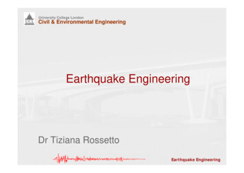
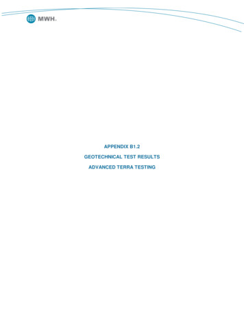
AccelerationSite Amplification Is CommonSandBABShaleRockAInstructional Material Complementing FEMA 451, Design ExamplesGeotechnical 15-4 - 7The soil profile acts as filter modifying the amplitude and nature of themotions.FEMA 451B Topic 15-4 NotesGeotechnical Engineering 15-4 - 7
Site Effects on Ground MotionsConservation of energy drives amplificationInstructional Material Complementing FEMA 451, Design ExamplesGeotechnical 15-4 - 8Structures founded on soils, especially if soft, tend to be subjected tostronger shaking with longer-period motions. The conservation of energyand the amplification process is important to illustrate here.FEMA 451B Topic 15-4 NotesGeotechnical Engineering 15-4 - 8
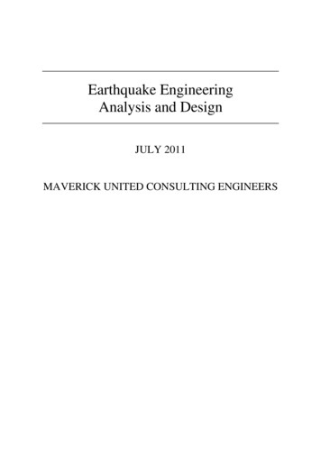
Amplification DefinitionsFree SurfaceOutcropSoilRockBedrockAmplification Free SurfaceBedrockAmplification Free SurfaceOutcropFigure adapted from Rix, G. J., (2001)Instructional Material Complementing FEMA 451, Design ExamplesGeotechnical 15-4 - 9Amplification can be defined in different ways and the method used shouldbe clearly specified.FEMA 451B Topic 15-4 NotesGeotechnical Engineering 15-4 - 9
Amplification Definitions Fourier amplification spectraa free surface (f )aoutcrop (f ) Spectral amplificationSa, free surface (T )Sa, outcrop (T )Instructional Material Complementing FEMA 451, Design ExamplesGeotechnical 15-4 - 10Amplification can be defined differently as depicted in this slide.FEMA 451B Topic 15-4 NotesGeotechnical Engineering 15-4 - 10
Soft Soils Commonly AmplifyMotions Relative To BedrockInstructional Material Complementing FEMA 451, Design ExamplesGeotechnical 15-4 - 11Soils can amplify or de-amplify so codes make conservative assumption thatthis will occur in specifying general procedures.FEMA 451B Topic 15-4 NotesGeotechnical Engineering 15-4 - 11
Effects of Local Soil ConditionsInstructional Material Complementing FEMA 451, Design ExamplesGeotechnical 15-4 - 12General curves such that shown above are only approximate studies. Whensuch data are used in building codes to account for soil amplification, themost conservative assumption about the amplification potential of the soils isassumed.FEMA 451B Topic 15-4 NotesGeotechnical Engineering 15-4 - 12
1985 Mexico City EarthquakeInstructional Material Complementing FEMA 451, Design ExamplesGeotechnical 15-4 - 13The 1985 Mexico City earthquake was centered abut 400 km from the city,but the motions were amplified by the underlying soft sediments (LakeTexcoco).FEMA 451B Topic 15-4 NotesGeotechnical Engineering 15-4 - 13
1985 Mexico City AccelerogramsInstructional Material Complementing FEMA 451, Design ExamplesGeotechnical 15-4 - 14Motions on the lake bed were higher and longer in period relative to nearbyrock sites.FEMA 451B Topic 15-4 NotesGeotechnical Engineering 15-4 - 14
1985 Mexico City – Juarez HospitalInstructional Material Complementing FEMA 451, Design ExamplesGeotechnical 15-4 - 15Typical example of tall building failures on lake bed area of Mexico City.FEMA 451B Topic 15-4 NotesGeotechnical Engineering 15-4 - 15
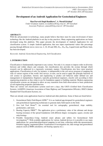
1985 Mexico City – Response SpectraInstructional Material Complementing FEMA 451, Design ExamplesGeotechnical 15-4 - 16Motions on lake bed area of Mexico City (blue curve) were far above thedesign spectra for that region (yellow curve).FEMA 451B Topic 15-4 NotesGeotechnical Engineering 15-4 - 16
1989 Loma Prieta EarthquakeInstructional Material Complementing FEMA 451, Design ExamplesGeotechnical 15-4 - 17Note the epicenter of the 1989 Loma Prieta earthquake was 65 miles southof San Francisco where most damages occurred.FEMA 451B Topic 15-4 NotesGeotechnical Engineering 15-4 - 17
San Francisco Bay Geological Map Soft deposits in red(Bay mud)Instructional Material Complementing FEMA 451, Design ExamplesGeotechnical 15-4 - 18Red zones indicate recent soft sediments with a high amplification potential.FEMA 451B Topic 15-4 NotesGeotechnical Engineering 15-4 - 18
San Francisco Marina DistrictInstructional Material Complementing FEMA 451, Design ExamplesGeotechnical 15-4 - 19The Marina District in San Francisco is built atop soft sediments and issusceptible to high amplification (and liquefaction due to sand fill).FEMA 451B Topic 15-4 NotesGeotechnical Engineering 15-4 - 19
Damage in Marina DistrictInstructional Material Complementing FEMA 451, Design ExamplesGeotechnical 15-4 - 20Typical damage in the Marina District following the 1989 earthquake.FEMA 451B Topic 15-4 NotesGeotechnical Engineering 15-4 - 20
Cypress Structure CollapseInstructional Material Complementing FEMA 451, Design ExamplesGeotechnical 15-4 - 21Aerial photo of collapsed Cypress Structure. Photo from Idriss (2002).FEMA 451B Topic 15-4 NotesGeotechnical Engineering 15-4 - 21
Instructional Material Complementing FEMA 451, Design ExamplesGeotechnical 15-4 - 22Slide from Idriss (2002). Yellow shaded zone indicates soft soils thatamplified ground motions above those in nearby stiffer soil areas. Theparticular section of the Cypress Structure that collapsed was founded onthese soft soils.FEMA 451B Topic 15-4 NotesGeotechnical Engineering 15-4 - 22
Cypress Structure CollapseInstructional Material Complementing FEMA 451, Design ExamplesGeotechnical 15-4 - 23The Cypress Overpass was demolished following the 1989 earthquake.FEMA 451B Topic 15-4 NotesGeotechnical Engineering 15-4 - 23
Effects of Local Soil ConditionsInstructional Material Complementing FEMA 451, Design ExamplesGeotechnical 15-4 - 24General curves such as that shown above are only approximate studies.When such data are used in building codes to account for soil amplification,the most conservative assumption about the amplification potential of thesoils is assumed.FEMA 451B Topic 15-4 NotesGeotechnical Engineering 15-4 - 24
Effects of Local Soil ConditionsInstructional Material Complementing FEMA 451, Design ExamplesGeotechnical 15-4 - 25Soft soils decrease the spectral response relative to some stiff soils, but therange over which the motions are near their maximum is broadened.FEMA 451B Topic 15-4 NotesGeotechnical Engineering 15-4 - 25
Pre-Loma Prieta Design SpectraInstructional Material Complementing FEMA 451, Design ExamplesGeotechnical 15-4 - 26Spectral design curves used prior to the 1989 Loma Prieta earthquake. Notethe S4 design curve for soft soils. As will be shown in the following slide, themotions from the 1989 quake greatly exceed the design spectrum beingused at the time. The slide was developed from Treasure Island, a deep softsoil site. This prompted the development of Category F for such soils thatrequire site-specific analysis instead of simplified analysis (see followingslides from IBC 2003 procedure).FEMA 451B Topic 15-4 NotesGeotechnical Engineering 15-4 - 26
Spectrum from 1989 Loma Prieta atDeep Soft Soil SiteReason forF Categoryin IBC 2003Instructional Material Complementing FEMA 451, Design ExamplesGeotechnical 15-4 - 27The motions from the 1989 quake greatly exceed the design spectrum beingused at the time. The slide was developed from Treasure Island, a deep softsoil site. This prompted the development of Category F for such soils thatrequire site-specific analysis instead of simplified analysis (see followingslides from IBC 2003 procedure).FEMA 451B Topic 15-4 NotesGeotechnical Engineering 15-4 - 27
IBC2003 – “F” Requires Site-specific AnalysisInstructional Material Complementing FEMA 451, Design ExamplesGeotechnical 15-4 - 28Note special provisions for F sites. These site conditions are of particularconcern for seismic analysis. F site involved soft soils that can greatlyamplify ground motions, such as in Mexico City in 1985 or Loma Prieta in1989 or liquefiable soils.FEMA 451B Topic 15-4 NotesGeotechnical Engineering 15-4 - 28
IBC2003 – “F” Requires Site-specific Analysis Determine site class based on top 30 m:Instructional Material Complementing FEMA 451, Design ExamplesGeotechnical 15-4 - 29Note special provisions for F sites. These site conditions are of particularconcern for seismic analysis. F site involved soft soils that can greatlyamplify ground motions, such as in Mexico City in 1985 or Loma Prieta in1989 or liquefiable soils. Site classification with IBC 2003 is a very importantissue. However, this procedure does not work well for highly stratified sites.FEMA 451B Topic 15-4 NotesGeotechnical Engineering 15-4 - 29
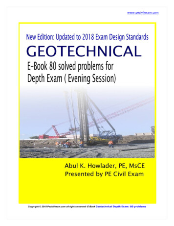
NEHRP Provisions Site Amplificationfor Site Classes A through ESite Class3.00ABCDEAmplification Fa2.502.001.501.000.50Site Class4.000.250.500.751.001.25Short Period Spectral Accel. Ss (g’s)ABCDE3.501.50Amplification 0.751.001.25Long Period Spectral Accel. S1 (g’s)Instructional Material Complementing FEMA 451, Design Examples1.50Geotechnical 15-4 - 30Note special provisions for F sites. These site conditions are of particularconcern for seismic analysis. F sites involved soft soils that can greatlyamplify ground motions.FEMA 451B Topic 15-4 NotesGeotechnical Engineering 15-4 - 30
Site Classification from? NEHRP Provisions allow siteclassification to determined from variousgeotechnical data, such as SPTblowcounts, undrained shear strength,and shear wave velocity measurements(Vs) Best approach in situ Vs measurementInstructional Material Complementing FEMA 451, Design ExamplesGeotechnical 15-4 - 31Provisions allow site classification to be determined from variousgeotechnical data, such as SPT blowcounts, undrained shear strength, andshear wave velocity measurements (Vs); shear wave velocity can bedetermined economically from CPTs in many cases.FEMA 451B Topic 15-4 NotesGeotechnical Engineering 15-4 - 31
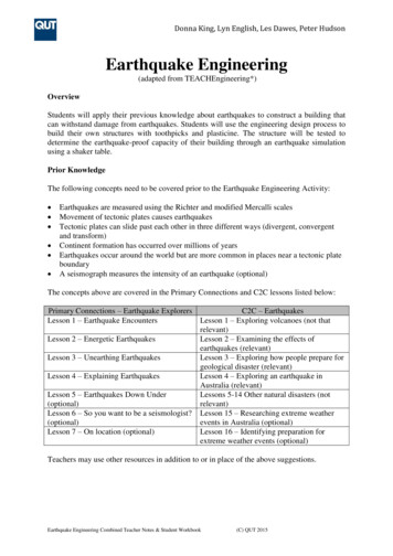
Field Tests To Measure Seismic Wave VelocitiesSourceDirect Pand SWavesDirect Pand SWaves3-DReceiversSource3 –D Receiversa. Crosshole TestingSourceb. Downhole TestingFluid-FilledBoreholeDirectS Waveb. Downhole Testing ArrangementVariousPropagationModes (bodyand interfacewaves)HorizontalReceiverc. Seismic Cone PenetrometerReceiver 1Receiver 2Sourced. Suspension LoggingCourtesy of K. H. Stokoe IIInstructional Material Complementing FEMA 451, Design ExamplesGeotechnical 15-4 - 32Shear wave velocity can be determined economically from CPTs in manycases; however, cross-hole tests are best.FEMA 451B Topic 15-4 NotesGeotechnical Engineering 15-4 - 32
Site Response Mechanisms Constant flux rate – impedanceρVsů2 constant Resonances within the soil columnHVsAmplificationVfn s4H Low-strain damping and apparentattenuation in soil Nonlinear soil behaviorτγDeamplificationFigure adapted from Rix, G. J., (2001)Instructional Material Complementing FEMA 451, De
Geotechnical Earthquake Engineering. Prentice Hall, 653 pp. Key Reference None. FEMA 451B Topic 15-4 Notes Geotechnical Engineering 15-4 - 3 Instructional Material Complementing FEMA 451, Design Examples Geotechnical 15-4 - 3 “While many cases of soil effects had been observed and reported for many years, it was not until a series of catastrophic failures, involving landslides at