Transcription
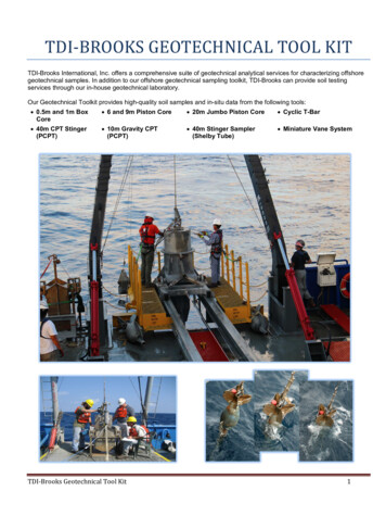
TDI-BROOKS GEOTECHNICAL TOOL KITTDI-Brooks International, Inc. offers a comprehensive suite of geotechnical analytical services for characterizing offshoregeotechnical samples. In addition to our offshore geotechnical sampling toolkit, TDI-Brooks can provide soil testingservices through our in-house geotechnical laboratory.Our Geotechnical Toolkit provides high-quality soil samples and in-situ data from the following tools: 0.5m and 1m BoxCore 6 and 9m Piston Core 20m Jumbo Piston Core Cyclic T-Bar 40m CPT Stinger(PCPT) 10m Gravity CPT(PCPT) 40m Stinger Sampler(Shelby Tube) Miniature Vane SystemTDI-Brooks Geotechnical Tool Kit1
OVERVIEWTDI-Brooks offers offshore, nearshore, and inland marine geotechnical survey services using a suite of innovativetools for soil sampling and measurement, including box corers (BC), piston corers (PC), gravity corers (GC), jumbopiston corers (JPC), deep-reaching Shelby tube samplers (SPLR), and piezocone penetrometers including ourCPT-Stinger and our Gravity CPT tool (gCPT). Figure 1 compares the soil depth below mudline that each of thesetools can reach. All of these tools can fully operate in waters as deep as 4,000 m, and each can be fitted with aUSBL transponder for precise lateral targeting. The tools are used to perform specified geotechnical and geologictesting on the soil to determine the pertinent physical properties and geologic interpretations.Figure 1) TDI-Brooks Marine Geotechnical Sampling Tool KitThe coring tools can recover continuous high quality undisturbed soil samples from the marine soil bed using a50x50x50-cm (½-m-deep) or 50x50x100-cm (1-m-deep) box corer, a 3-inch ID piston or gravity corer, or a 4-inch IDJumbo Piston Corer. Additionally, ASTM-quality piezocone penetrometer (PCPT) data can be collected using ourinnovative CPT-Stinger and gCPT tools. The CPT-Stinger gathers high quality PCPT data by being inserted to itsfull tool length into the soil and converting the acquired dynamic data to static values. It then advances its stilllogging cone another tool-length into the soil at ASTM standard rates. The gCPT tool rapidly acquires high-qualityPCPT data by inserting its cone ballistically into the soil and converting its acquired dynamic data to static values.All dynamically acquired PCPT data are normalized back to static data values using the known rate effectadjustment applied to the instantaneous insertion velocities measured every 2 ms by the tool. So-adjusted dynamicdata profiles match static data profiles with negligible deviation, as we have published and proved with years ofside-by-side tests.TDI-Brooks Geotechnical Tool Kit2
TDI-Brooks also offers an innovative and cost-effective formation soil sampling tool called the Stinger Sampler(SPLR). The basic idea behind the deepwater Stinger SPLR system is to “transport” a Shelby tube down throughthe soil to acquire undisturbed, geotechnical-quality core samples at depths down to 40 m BML, thus nicelycomplementing the 0-20m continuous JPC soil samples and the 0-40 m continuous PCPT data. In practice, aShelby tube sample can be acquired at any specified depth down to 40 m, with each successive deployment of thetool.The economic benefits of quickly and accurately acquiring from a modest-cost vessel several high-qualitygeotechnical soil samples and PCPT profiles to 40 m BML are readily apparent. These tools allow more highquality data to be acquired for a given budget, and affords more areal coverage through rapid deployment,compared to the amount of data obtainable from a much more expensive conventional soil boring. Thus, the TDIBrooks geotechnical seabed sampling kit of tools helps reduce the overall risks associated with foundation designand installation planning.BOX CORING (BC) SYSTEMThe TDI-Brooks box coring systems consist of hardware assemblies designed to be rigged together into a workingcore rig and deployed to the seabed for extracting a standard cubic box core. Such a core is 50cm x50cmx100cm(1-m deep) or 50cm x 50cm x50cm (0.5-m deep) in size.Our box coring system is designed to be a safe, simple, effective mechanism for acquiring large-volumeundisturbed shallow sediment samples from the seabed or lakebed. Such samples are essential for the accuratedetermination of geotechnical characteristics of submerged sediments, as well as for the assessment of the benthicecology (infauna) as required in marine environmental impact assessments. Figure 2 is a photo of both sizes ofTDI-Brooks box corer.The sample box of the core rig is fabricated from stainless steel and is clean and smooth to minimize frictionalresistance between the box and the sediment. The corers have a adjustable weight capability so that the weightstack can be fine-tuned to suit the different seabed conditions that may be encountered.Figure 2) TDI-Brooks Half-Meter And One-Meter-Deep Box Coring RigsTDI-Brooks Geotechnical Tool Kit3
The BC system is rigged to the main coring rope with a safety shackle, and then its trigger assembly is set fordeployment. The main coring rope is load-tested and regularly inspected with Tuck eye splice termination woveninto its loose end. The main winch, main coring rope, and the coring A-Frame is used for deploying and retrievingthe box corer. In addition to the deployed hardware, support gear is mounted to the vessel working deck to managethe deployment and retrieval of the coring rig. These include the heel-block assembly and the main sheave fromthe coring A-Frame. Once the box corer is safely deployed, it is lowered to the seabed while performing thenavigation protocols for lateral positioning, and then a core sample is acquired at the client-specified site.Upon retrieval on deck the box corer is secured with the safety pin in the closed position and placed on its stand.The lid is opened and the contents inspected for quality and acceptability of the box core sample. The overlyingwater is siphoned off (gently as the water level approaches the surface of the mud so as to not disturb the surficiallayers) to expose the sediment for sub-sampling, descriptions, and photography. The box corer is typically tiltedslightly to one corner to facilitate pooling of the last amounts of water. A picture of the BC system with water beingsiphoned off is shown in Figure 3.Figure 3) Siphoning Water From The Top Of A Box Core SampleThe sample is accepted if all the following conditions are met, and re-attempted if not: Box core jaws are fully closed and the box core is sealed. Water is not streaming out from the jaws of theclosure device. Box core lid is closed. Overlying water in the box core is mostly clear. A box core sample with muddy water indicates a disturbanceof the surficial layers. Surface of sediment is undisturbed (soil on the lid is disturbed by definition), not tilted, slumped or washedout. A sample with a tilted surface (corer sticking at an angle less than perpendicular to the sedimentsurface) may be used with the appropriate precautions. Soil sample depth is greater than the minimum required.For each cast or drop of the box corer, the following information is recorded on the sample log sheet and thesample labels:Date and time on bottomWater depth (wire indicator and fathometer)Site or Station Number,Penetration Depth (distance of sediment surface from lid of corer; soil sample depth is calculated from this)Pertinent comments regarding quality, etc. A brief description of the sediment surface noting texture, color,depth of loose surface layer, and any life seen for each box core. Digital photographs are taken of surface of representative box cores. Photographs are taken of any unusualsurface features. TDI-Brooks Geotechnical Tool Kit4
After the box corer is retrieved on board and is secured in its stand (Figure 4), Minivane (Figure 5) and/or T-bar(Figure 6) testing is conducted at vertical intervals as specified by the client. Minivane readings are recorded onthe Laboratory Sample Sheet along with a description of the box core sample. The least disturbed part of the coresample is typically sub-sampled with push-core tubes (Figure 7). The bottom ends of these push-core tubes arepre-beveled to produce a cutting edge no larger diameter than the ID of the tube. The sub-sampling tubes areplaced approximately 2 inches apart. A digital photograph is taken.Figure 4) Processing the Box CoreThe bottom and top of the tubes are then capped immediately (the bottom capped before extraction from the bodyof soil in the rig). The tops and bottoms of the tubes are marked and the tubes are labeled. The tubes are storedand secured in a vertical position in a manner that minimizes vibrations and bumping. All tube and bulk samplesare delivered to the onshore geotechnical testing laboratory in a timely, uninterrupted, temperature-controlledmanner after completion of the coring activities.Figure 5) Miniature Vane On Box Core And TorvaneTDI-Brooks Geotechnical Tool Kit5
Figure 6) T-Bar Measurements On Box CoreFigure 7) Box Core Sub-Sampled With Push-Core TubesTDI-Brooks Geotechnical Tool Kit6
MINIATURE VANE SYSTEMThe TDI-Brooks miniature vane instrument measures the torque and rotation at a vane shaft using the conventionalASTM method calibrated torque spring set and potentiometer, respectively. Its operation consists of inserting thevane into the soil sample and rotating it at a constant rate to determine the torque required to cause a cylindricalsurface to be sheared by the vane. The torque is converted to a unit shearing resistance (shear strength) of thecylindrical surface area. The shear strength reported is the peak strength determined from the torque vs. rotationplot. In addition to the peak shear strength, the residual strength is determined from the same plot if the failure isnot dominated by cracking of the sample. In the analysis of vane tests, it is assumed that a cylinder of sediment isuniformly sheared around the axis of the vane in an undrained condition with cohesion as the principal contributorto shear strength.The standard motorized vane apparatus rotates at a constant rate of 10 per minute and includes the standard 0.5”x 0.5” (12.7 x 12.7-mm) vane. The special ASTM version S2301 has a speed of rotation at the faster rate of 60 to90 per minute to conform to ASTM D4648 and is supplied with the alternative vane measuring 1" x 1" (25.4 x25.4mm). Load on either version is applied through one of the 4 calibrated springs supplied. These springs are keptrecently calibrated and a certificate of such is provided. A second calibrated spring set is provided for backup. Theserial number of the spring set in service is recorded on each datasheet. Figure 8 is a photo of one of our Minivaneinstruments, calibrated torque spring sets, and vanes ready for service.Figure 8) TDI-Brooks Minivane System, Ready For ServiceTDI-Brooks Geotechnical Tool Kit7
AUTO T-BAR SYSTEMThe TDI-Brooks Auto T-Bar instrument measures the progressive resistance of a soil column to a cylindrical rod(shaped as an upside-down T) as it advances down the soil column at a constant and standard rate of travel. Theinstrument is shown in Figure 9, with its T-bar protruding below.Operation consists of mounting the instrument onto a box corer containing an undisturbed seabed soil sample,connecting the instrument to a shipboard source of compressed air, and starting the automatic advance of the TBar into the soil sample. The resistance of the soil is automatically logged during the downward advance until thebottom of the soil sample is reached by the T-bar. The instrument then reverses T-bar movement and logs the soilresistance generated during the upward, retracing return of the T-bar back up to any desired soil depth or to thesurface. This sequence of a downward stroke followed by upward re-trace through the failed soil can be continuallyrepeated as many times as desired. Sets of 10 to 30 such cyclic T-bar tests are typical in box cores.Figure 9) TDI-Brooks Auto T-BarTDI-Brooks Geotechnical Tool Kit8
The instrument measures and logs the soil’s resistive force on the T-bar 10 times per second. The T-bar typicallyauto-advances at 2.0 cm/sec, so a data set is logged every 2 mm of penetration (this standard rate of advance canbe changed to address differing client specifications). A single down-stroke test to 100 cm soil depth thus takes 50seconds with 500 resistive force measurements logged (Table 1). The resistive force is reported in pounds ornewtons, and is converted by the processing program into units of pressure (ksf or kPa) by dividing by thecylindrical cross-sectional area of the T-Bar. The standard (medium) T-Bar cylinder diameter is 1.00 in. and itslength is 5.00 inches. Smaller T-bars (0.75 in. and 0.50 in. dia.) are also available for quick change-out, each withcylinder length 5 times its diameter. The push rod is sleeved, rendering its frictional drag during advance in eitherdirection to have no measureable component. The calibrated range of the tool is -100 lb (445 N) upstroke to 100lb downstroke, which translates using an Nt-bar of 10.5 to maximum measureable undrained shear strengths ofabout 275 psf (13.2 kPa) using the large bar, 500 psf (23.9 kPa) for the medium bar, and 1,100 psf (52.7 kPa) forthe small bar. An example of 30 cyclic auto T-bar measurements into a 1m deep box core sample are plotted inFigure 10.In this figure, the pink trace represents the initial downward stroke of the T-bar into the soil. The two (right and left)nested sets of blue traces are the subsequent progressive upstroke and downstroke data, with the inner tracesbeing the 30th and final stroke set. All measurements have been converted using an Nt-bar of 10.5 to representundrained shear strength. This plot illustrates the progression of soil reworking toward fully remolded characterduring the course of the 30 sets of strokes. Such a data set can thus be also used to project fully remolded valuesat selected soil depths.Figure 10) Example Plot Of Auto T-Bar Cyclic DataTDI-Brooks Geotechnical Tool Kit9
Table 1. Auto T-Bar SpecificationsTDI-Brooks Geotechnical Tool Kit10
PISTON CORING (PC) SYSTEMThe TDI-Brooks 3-inch-diameter piston coring (PC) system consists of various hardware assemblies designed tobe safely and robustly fastened together into a working core rig and deployed to the seabed for extracting a pistoncore. Such a core rig can be assembled to be 10 to 40 feet long and is 3 inches in barrel ID. An example of a corerig ready for deployment is shown in Figure 11.The deployed core rig comprises component assemblies of the core head, the core barrel, the piston, and thetrigger system. The core head assembly is made up of a 2,000 lb lead-weighted core head with nosepiece and acoupling with which to attach lengths of core barrel sections. It also has a lifting flange assembly that attaches tothe trigger system. The trigger assembly is made up of the trigger pendant, trigger arm, pendant clamp, triggerweight, trigger wire, and trigger wire connecting system. The core barrel assembly is made up of selected lengthsof core barrel sections, connecting collars, a core liner inside the barrel assembly, a core catcher, a core cutter,and set screws to hold the barrel assembly together. The barrel length can be adjusted in 5-foot increments byadding 5 or 10-ft barrel sections and connecting collars. The rig shown in Figure 11 has a barrel that is 20-ft long,using one 10-ft barrel section and one 5-ft barrel section, and with the uppermost 5 ft of barrel built inside the corehead. The extended piston corer (XPC) employs an additional barrel section and a longer trigger pendant.The main winch, main-line coring rope, and the PC coring A-Frame are used for deploying and retrieving the 3-in.piston core rig on TDI-Brooks vessels. In addition to the deployed hardware, several assemblies are mounted tothe vessel working deck to manage the deployment and retrieval of the coring rig. These assemblies include themain sheave from a starboard or port-side coring A-Frame, as well as core-head and trigger tugger winches withtheir hydraulic power pack.Figure 11) TDI-Brooks 3-Inch Piston Coring RigTDI-Brooks Geotechnical Tool Kit11
We also have a deployment system for use on 3rd-party vessels not having a provision for a side-mount A-frame.This system includes a stern deployment track in addition to the kit described above. A schematic with dimensionsis shown in Figure 12. A photo of the system in operation on a 3rd-party vessel is shown in Figure 13.Figure 12) TDI-Brooks 3-Inch Piston Coring Track For 3rd-Party VesselsFigure 13) TDI-Brooks 3-Inch Piston Coring Track On A 3rd-Party Vessel.TDI-Brooks Geotechnical Tool Kit12
A piston corer uses a free fall of the coring rig to achieve the desired initial force on impact, and a sliding pistoninside the core barrel to reduce inside wall friction with the sediment and to assist in the rapid evacuation ofdisplaced water from the top of the corer. These elements act in concert to maximize core recovery. It uses atrigger assembly to release and allow the corer to free-fall with the core barrel tip starting just above the seabed.The impact speed of the piston corer into the bottom is independent of the winch payout speed. Proper pendantand trigger wire lengths, as well as stopping the winch payout upon trigger, are critical for the proper action of thepiston within the barrel. The sequence of piston coring events is shown in Figure 14.Figure 14) Schematic Of A PC Or JPC Operation At The SeabedReferring to the schematic: As the corer nears the bottom (A), the winch payout speed is slowed and preparationsare made to stop the payout at the instant of release. As the trigger weight impinges the seabed (B) the weight isreleased from the trigger arm, and the trigger arm begins to rise with respect to the rig. At this point, the core barreltip is still above the seabed. When the trigger arm has risen through its full travel (C), the corer is mechanicallyreleased to free-fall down through the seabed. At this point, the barrel tip of the corer is just above the seabed, asprogrammed by the proper length of the trigger wire. The moment of release is noted by the Winchman as asudden drop in main line tension. At the instant of release the payout of the winch is stopped, thus fixing the lengthof coring rope out. The corer separates from the trigger assembly and free-falls through the seabed, penetratingthe upper several meters of sediment. When the falling core rig reaches the end of its pendant slack, the internalpiston stops moving downward along with the core rig (D) and becomes fixed with respect to its height about theseabed. The still-falling core barrel then creates suction (much like a syringe and its plunger) between the pistonand the soil entering the barrel, enhancing the distance the soil sample will move up the barrel.The length of the trigger wire, the length of the pendant, and the halting of the rope payout are in concert such thatthe main rope becomes taut just as the core cutter at the bottom of the barrel comes within a few inches of theseabed. This results in a core with about a few inches of water head between the bottom of the piston and the soilsurface inside the liner. When downward momentum of the core has stopped with complete penetration, a slowpullout on the winch is begun. At the initial stage of pullout, the piston slowly moves to the top of the core barrel inresponse to the Winchman’s tension on the core wire. The piston has a built-in check valve so that water can passthrough it when it is moving at slow speed (E). It fetches up against the stop in the core head, and the corer ispulled from the seabed.TDI-Brooks Geotechnical Tool Kit13
Retrieval after pullout can proceed as fast as the winch is capable. Winch speed is typically 60 to 80 meters of lineper minute. The piston prevents washout of the sample from the top, and the core catcher prevents the samplefrom backing down out of the barrel tip. In extremely sandy areas, if core material is lost during the retrievalprocess, typically a “sock” is put in the core cutter to act as a one-way valve, and re-sampling at the site isperformed in an attempt to obtain greater recovery.A picture of the core rig barrel end with the cutter and catcher removed to show the internal piston protruding isshown at left in Figure 15. The core liner inside the barrel is visible. At right the installed cutter/catcher/pistonassembly is shown. To rig the PC system, a load-tested PC pendant is inserted with one end hanging out thebottom of the core barrel and the other end hanging out the top of the core head. A piston pin is installed to connectthe bottom end of the pendant to the piston (the pin is barely visible in the photo), and then the piston, catcher, andcore cutting shoe are mounted to the bottom end of the core barrel with set screws.Figure 15) Barrel End Of The PC Rig With Piston ShowingThe trigger assembly is attached to the top 3 ft section of the pendant by clamping the trigger assembly bar on thependant, and then properly configuring and securing the trigger assembly to the core head assembly. The systemis rigged in such a way that the pendant wire rope will come out of the core head with the proper amount of extraloop available, as dictated by the core barrel length and soil strength at that location. This results in programming afree-fall loop in the pendant of precise distance.All of the described lifting/rigging gear is regularly load tested and inspected. The main coring rope have a loadtested and inspected Tuck eye splice termination woven into its loose end. The pendant is connected to thistermination using a pendant pin. This assembly is designed to roll through the sheave and heel block. For thisreason, a rope thimble is not used in the termination loop, because the roll-thru-the-sheave acts with the thimble toincrementally cut and wear the rope over time.The main winch, main coring rope, and the port A-Frame are used for deploying and retrieving PCs. In addition tothe deployed hardware, several assemblies are mounted to the vessel working deck to manage the deploymentand retrieval of the coring rig. These include the track/bucket/heel-block assembly, the main sheave from the portA-Frame, and the core head and trigger tugger winches with their hydraulic power pack.Safety precautions are paramount in our coring procedures and are regularly reinforced through safety meetings,JSAs, toolbox meetings, and other elements of our Safety Management System.The following is a summary of our PC sample processing procedures:Upon core retrieval, the core liner is removed, carefully carried and placed in the processing trough, and cut into 3foot lengths. The core liner is marked with a water proof marker into 3foot long lengths, starting with the topsection. For PCs, the top section is a 3-ft section because the top-most sediment is very soft and a short section isdifficult to handle and to measure for soil strength. (NOTE: these cores will virtually always have one short or long“odd” section, due to recovery length not being an exact multiple of 3 ft. The short section of a JPC will be the topsection, whereas the odd section of a PC will be the bottom section.) Each section is numbered with a SectionNumber and an arrow pointing to the top.TDI-Brooks Geotechnical Tool Kit14
The bottom end of the section is capped immediately after cutting. The top and bottom of the liner section aremarked as outlined in a Field Sediment Testing Protocol. This information is recorded immediately in the Corelog. Any smell of hydrogen sulfide (rotten egg smell) is noted on the log.A digital photograph is taken and a visual description of each section is recorded. Lab testing as outlined in theField Sediment Testing Protocol is performed and the top of the core section is capped. Top and bottom capsare securely taped to the liner. The core sections are stored and secured in a vertical position with the deeperportion of the section on the bottom. The core sections are stored in a manner to minimize individual movementwith vessel heave, pitch, and roll. After completion of the coring activities, the core sections are delivered to theonshore geotechnical testing laboratory in a timely, uninterrupted manner.JUMBO PISTON CORING (JPC) SYSTEMThe TDI-Brooks jumbo piston coring (JPC) system consists of various hardware assemblies designed to befastened together into a working core rig and deployed to the seabed for extracting a “jumbo” piston core. Such acore rig can be assembled to be 34 to 64 feet long and is 4 inches in barrel ID (Figure 16). The deployed core rigcomprises assemblies for the core head, the core barrel, the piston, and the trigger system. The core headassembly is made up of a 5,000 lb lead coring weight with an inserted flange-barrel and coupling with which toattach lengths of core barrel in 5 and 10 ft. sections. It also has a lifting assembly that attaches to the triggersystem. The core barrel assembly is made up of selected sections of core barrel, connecting collars, a core linerassembly inside the barrel assembly, a core catcher, a core cutter, and set screws to hold the barrel assemblytogether. The barrel length can be adjusted in 5-foot increments by adding these barrel sections and connectingcollars.Figure 16) TDI-Brooks Jumbo Piston Coring RigTDI-Brooks Geotechnical Tool Kit15
The trigger assembly is made up of the trigger pendant, trigger arm, pendant clamp, trigger weight, trigger wire,and trigger wire connecting system. The assembled core rig weighs between 5,500 and 7,500 lb, depending on thelength of core to be acquired. The weight of the core head is adjusted by adding weight as lead ingots to a startingweight of about 5,000 lb.The TDI-Brooks extended jumbo piston coring (XJPC) system consists of various hardware assemblies designedto be fastened together into a working core rig and deployed to the seabed for extracting an even longer pistoncore. Such a core rig can be assembled to be 74 feet long and is 4 inches in barrel ID. This additional length ismade possible by adding track extensions to the forward end of the track. These extensions can be quicklyremoved and secured for core processing.The main winch, main-line rope, and the stern A-Frame are used for deploying and retrieving the JPC rig. Inaddition to the deployed hardware, several assemblies are mounted to the vessel working deck to manage thedeployment and retrieval of the coring rig. These assemblies include the main sheave from the stern A-Frame andthe deployment, retrieval and trigger tugger winches with their hydraulic power pack.As the JPC trigger weight impinges the seabed and the trigger arm rises, the corer is released to free-fall into theseabed. At the moment of release, the payout of the winch is immediately stopped, thus fixing the length of coringrope out. The corer separates from the trigger and free-falls the mechanically-programmed distance into theseabed. The piston is set to stop moving vertically down when it is just above the seabed, but the core barrelcontinues to move down into the sediment.Figure 17 is a screen-capture of the actual profile-view track of the JPC transponder from our APOS computer as itis lowered the last 80 meters above a target and then free-fell into the seabed. The free-fall track is seen from theprofile to be about 23 m in vertical drop. The JPC rig for this core is 20 m long and the free-fall before the corecutter entered the seabed is about 2.5 m, so this profile gives confirmation that the rig penetrated fully into thesediment up to the top of the core head.Figure 17) Profile View Of The JPC Rig Before, During, And After Free-FallTDI-Brooks Geotechnical Tool Kit16
Once the rig settled into the seabed in this example, we logged position for a minute, and then extracted the rig.This sequence can also be seen in the profile view of the figure. Once we confirmed that the rig is fully out of theseabed the Winchman increased winch speed and retrieved the rig. We have learned from experience that our JPCrig will sometimes “glance off” of stiff sediments on gradients more than about 22 from horizontal, so our policy isto make coring attempts into seabed gradients of 20 or less.A step-wise photo sequence of a JPC rig in operation is presented as Figure 18. This sequence proceeds acrossthe first row, then across the second row, and so on.Figure 18) Stepwise Process Of JPC OperationsTDI-Brooks Geotechnical Tool Kit17
Each photo in the 15 frame photo sequence above represents the following:Deployment:(1) Loading core liner,(2) Pulling the rig sternward down its track,(3) Rotating the rig vertically into the water off the stern, and(4) Installing the trigger,Retrieval:(5) Securing the trigger pendant into its socket on the bucket to remove the trigger arm,(6) Retrieving the trigger weight,(7) Retrieving the core rig to the surface (it is now hanging on the bottom of the pendant),(8) Aligning the core rig with its bucket using the A-frame and main winch,(9) Securing the core rig into its bucket,(10) (11) & (12) Extracting the core rig and its bucket from vertical to horizontal,(13) Reaching the stop on the track,(14) Removing the core cutter shoe at the bottom of the rig, and(15) Extracting the core inside the core liner.The JPC system is rigged by inserting a load-tested JPC pendant with the eye end hanging out the bottom of thecore barrel and the double pronged jaw end hanging out the top of the core head. The piston pin is installed toconnect the eye end of the pendant to the piston within the pre-assembled piston/cutter/catcher assembly, andthen the piston/cutter/catcher assembly is mounted to the bottom end of the core barrel with set screws. The triggerassembly is attached to the pendant by unscrewing the knurled-nut cap of the pendant pin, placing the triggerassembly eye in the jaw, inserting the pen
geotechnical samples. In addition to our offshore geotechnical sampling toolkit, TDI-Brooks can provide soil testing services through our in-house geotechnical laboratory. Our Geotechnical Toolkit provides high-quality soil samples and in-situ data from the following tools: 0.5m and 1m Box Core 6 and 9m Piston Core 20m Jumbo Piston .