Transcription
Environmental Impact Assessment Report: Volume 3Part B of 6Appendix A18.1 Ground Investigation Factual ReportsReport TitleGreater Dublin Drainage Ground Investigation – Phase II Terrestrial InvestigationSummary Report on the Bathymetric and Geophysical Data Integration for the GDD Scheme for TechworksMarineReport on the Geophysical Investigation for GDD Scheme, Offshore PortmarnockReport on the Geophysical Investigation for GDDP Portmarnock Golf Course, DublinGreater Dublin Drainage Offshore Site Investigation of Outfall PipelineGreater Dublin Drainage Scheme - Sub-Bottom AnalysisGreater Dublin Drainage Scheme - Hydrographic Survey Report GE013 GDDGreater Dublin Drainage Scheme Fingal County Council TW/12/PRJ-007Greater Dublin Drainage Scheme Preliminary Ground Investigation Contract - Phase 1 Factual Report onGround Investigation (Report No. 16695)32102902/EIAR/3B
FINAL FOR ISSUEGreater Dublin Drainage Ground Investigation –Phase II Terrestrial InvestigationPrimary Author:Matthew GilbertClient:Irish WaterClient’s Representative:Tobin Consulting EngineersCompleted:April 2015Report No.:14-645File Location:14-645 Report
Site Name: Greater Dublin DrainageGI Phase IIReport No.: 14-645CONTENTSDocument Control SheetNote on: Methods of describing soils and rocks & abbreviations used on exploratory hole logs1AUTHORITY . 42SCOPE . 43DESCRIPTION OF SITE . 44SITE OPERATIONS . 54.1Boreholes . 54.24.34.1.1 Light cable percussion boreholes . 54.1.2 Boreholes by combined percussion boring and rotary follow-on drilling . 64.1.3 Rotary drilled boreholes . 7Standpipe installations . 7Trial Pits . 85LABORATORY WORK . 86GROUND CONDITIONS . 86.1General geology of the area . 86.2Ground types encountered during investigation of the site . 96.3Groundwater . 97REFERENCES . 10APPENDICESAppendix ASite and exploratory hole location plansAppendix BBorehole logsAppendix CCore photographsAppendix DTrial pit logsAppendix ETrial pit photographsAppendix FLaboratory test resultsAppendix GSPT hammer energy measurement reportAppendix HGeophysics report (Apex Geoservices)April 2015Page 1
Site Name: Greater Dublin DrainageGI Phase IIReport No.: 14-645Document Control SheetReport No.:14-645Project title:Greater Dublin Drainage Ground InvestigationPhase II Terrestrial InvestigationClient:Irish WaterClient’s Representative:Tobin Consulting EngineersRevisionStatusReport prepared by:Report reviewed by:Report approved by:Issue dateA01FinalMatthew GilbertMEarthSci FGSDarren O’MahonyBSc MScPaul DunlopBEng PhD CEng MIEI10 April 2015The works were conducted in accordance with:Site Investigation in Construction Part 3: Specification for Ground Investigation,Site Investigation Steering Group, published by Thomas Telford Ltd (1993)British Standards Institute (2010) BS 5930:1999 A2: 2010, Code of practice for site investigations.Incorporating Amendment Nos. 1 and 2, as partially replaced by: BS EN 1997-2:2007: Eurocode 7. Geotechnical design. Ground investigation and testing BS EN ISO 22475-1:2006: Geotechnical investigation and testing. Sampling methods andgroundwater measurements. Technical principles for execution BS EN ISO 14688-1:2002: Geotechnical investigation and testing. Identification and classification ofsoil. Identification and description BS EN ISO 14688-2:2004: Geotechnical investigation and testing. Identification and classification ofsoil. Principles for a classification BS EN ISO 14689-1:2003: Geotechnical investigation and testing. Identification and classification ofrock. Identification and description BS EN ISO 22476-2:2005: Geotechnical investigation and testing. Field testing. Dynamic probing BS EN ISO 22476-3:2005: Geotechnical investigation and testing. Field testing. Standard penetrationtestApril 2015Page 2
Site Name: Greater Dublin DrainageGI Phase IIReport No.: 14-645Methods of describing soils and rocksSoil and rock descriptions are based on the guidance in Section 6 of BS 5930: 1999 A2: 2010, The Code of Practice for SiteInvestigation. The amendments revised the Standard to remove text superseded by BS EN ISO 14688-1:2002, BS EN ISO14688-2:2004 and EN ISO 14689-1:2003 and refers to the relevant standard for each affected subclause. However, thefollowing terms are used in the description of fine-grained soils, where applicable: soft to firm:fine-grained soil with consistency description close to the boundary betweensoft and firm soil (Table 13 of BS5930). firm to stiff:fine-grained soil with consistency description close to the boundary betweenfirm and stiff soil (Table 13 of BS5930).Abbreviations used on exploratory hole logsUNominal 100mm diameter undisturbed open tube samplePNominal 100mm diameter undisturbed piston sampleBBulk disturbed sampleDSmall disturbed sampleWWater sampleES / EWSoil sample for environmental testing / Water sample for environmental testingSPTStandard penetration test using a split spoon sampler (small disturbed sample obtained)SPT (C)Standard penetration test using 60 degree solid conex,x/x,x,x,xBlows per increment during the standard penetration test. The initial two values relate to the seatingdrive (150mm) and the remaining four to the 75mm increments of the test length.The length achieved is stated (mm) for any test increment less than 75mmN XSPT blow count ‘N’ given by the summation of the blows ‘X’ required to drive the full test length(300mm)N X/ZIncomplete standard penetration test where the full test length was not achieved. The blows ‘X’represent the total blows for the given test length ‘Z’ (mm)VVRShear vane test (borehole) Hand vane test (trial pit) Shear strength stated in kPaV: undisturbed vane shear strengthVR: remoulded vane shear strengthdd/mm/yy: 1.0dd/mm/yy: dryDate & water level at the borehole depth at the end of shiftand the start of the following shiftAbbreviations relating to rock core – reference Clause 44.4.4 of BS 5930: 1999TCR (%)Total Core Recovery: Ratio of rock/soil core recovered (both solid and non-intact) to the total length ofcore run.SCR (%)Solid Core Recovery: Ratio of solid core to the total length of core run. Solid core has a full diameter,uninterrupted by natural discontinuities, but not necessarily a full circumference and is measured alongthe core axis between natural fractures.RQD (%)Rock Quality Designation: Ratio of total length of solid core pieces greater than 100mm to the totallength of core run.FIFracture Index: Number of natural discontinuities per metre over an indicated length of core of similarintensity of fracturing.NINon Intact: Used where the rock material was recovered fragmented, for example as fine to coarsegravel size particles.AZCLAssessed zone of core loss: The estimated depth range where core was not recovered.DIFDrilling induced fracture: A fracture of non-geological origin brought about by the rock coring.April 2015Page 3
Site Name: Greater Dublin DrainageGI Phase IIReport No.: 14-645Greater Dublin Drainage Ground Investigation Phase II1AUTHORITYOn the instructions of Consulting Engineers, Tobin Consulting Engineers (“the Client’s Representative”),acting on the behalf of Irish Water (“the Client”), a ground investigation was undertaken at the abovelocation to provide geotechnical and environmental information for input to the design and constructionof a 17km long pipeline from Blanchardstown to Portmarnock.This report details the work carried out both on site and in the geotechnical and chemical testinglaboratories; it contains a description of the site and the works undertaken, the exploratory hole logs andthe laboratory test results.All information given in this report is based upon the ground conditions encountered during the siteinvestigation works, and on the results of the laboratory and field tests performed. However, there maybe conditions at the site that have not been taken into account, such as unpredictable soil strata,contaminant concentrations, and water conditions between or below exploratory holes. It should benoted that groundwater levels usually vary due to seasonal and/or other effects and may at times differ tothose measured during the investigation.This report was prepared by Causeway Geotech Ltd for the use of the Client and the Client’sRepresentative in response to particular instructions. Any other parties using the information containedin this report do so at their own risk and any duty of care to those parties is excluded.2SCOPEThe extent of the investigation, as instructed by the Client’s Representative, included boreholes, trial pits,soil and rock core sampling, in-situ and laboratory testing, geophysics survey, and the preparation of afactual report on the findings.3DESCRIPTION OF SITEThe Greater Dublin Regional Drainage Scheme consists of a waste water treatment works (WWTW) plantand accompanying pipeline with a marine outfall in North County Dublin. This phase of works focussedon the inland section of the pipeline, covering an area some 17km in length.April 2015Page 4
Site Name: Greater Dublin DrainageGI Phase IIReport No.: 14-645The route commences at the M50-N3 junction in Blanchardstown and progresses in an north-easterlydirection, parallel to the northern side of the M50. The route diverges slightly to the north of the M50.The route continues easterly towards the southern side of Silloge Golf Club and the M50-R108 junction atBallymun cross. The pipeline then runs towards Collinstown Business Park and heads to Clonshaugh, thesite of the proposed WWTW. This is located approximately 2.2km southeast of Dublin Airport andbetween the M1 and Malahide Road. The pipeline from Clonshaugh to the marine outfall progresses in anortherly direction before then turning east and running past Kinsealy. The pipeline then turns southbriefly, then finally east, crossing under the Dublin-Belfast railway line to the south of Portmarnock andnorth of Mayne Bridge.The site use is a mix of agricultural lands and residential areas. Primarily, site operations were carried outin agricultural lands.4SITE OPERATIONSSite operations which were conducted between 24th November 2014 and 12th February 2015, included: six percussion boreholes thirteen percussion boreholes with rotary follow-on one percussion borehole with Geobor S wireline rotary coring follow-on twelve rotary only boreholes thirteen trial pits.The exploratory holes and in situ tests were located as instructed by the Client’s Representative, as shownon the exploratory hole location plan in Appendix A.4.1BoreholesA total of thirty-two boreholes were put down through soils and rock strata to their completion depths bya combination of methods, including light cable percussion boring by Dando 2000 and 3000 rigs, androtary drilling by Comacchio 205, Comacchio 405 and Beretta T41 rotary drilling rigs.The borehole logs state the methodology and plant used for each location, as well as the appropriate depthranges.A summary of the boreholes, subdivided by category in accordance with the methods employed for theircompletion, is presented in the following sub-sections.4.1.1Light cable percussion boreholesSix boreholes (BH117, 120, 122, 134, 135 and 138) were put down to completion in minimum 200mmdiameter using Dando 2000 and Dando 3000 light cable percussion soil boring rigs. All boreholes wereApril 2015Page 5
Site Name: Greater Dublin DrainageGI Phase IIReport No.: 14-645terminated either at their scheduled completion depths, or else on encountering virtual refusal onobstructions, including large boulders and weathered bedrock.Hand dug inspection pits were carried out between ground level and 1.2m depth to ensure boreholeswere put down at locations clear of services or subsurface obstructions.Disturbed (bulk and small bag) samples were taken within the encountered strata. Undisturbed (UT100and U100) were taken where appropriate and as directed within cohesive soils. Environmental sampleswere taken at standard intervals, as directed by the Client’s Representative.Standard penetration tests were carried out in accordance with EC7 at standard depth intervals using thesplit spoon sampler (SPT) or solid cone attachment (SPTc). The penetrations are stated for those tests forwhich the full 150mm seating drive or 300mm test drive was not possible. The N-values provided on theborehole logs are uncorrected and no allowance has been made for energy ratio corrections. The SPThammer energy measurement report is provided in Appendix G. Details of the SPT hammer used areprovided on the individual borehole logs.Any water strikes encountered during boring were recorded along with any changes in their levels as theborehole proceeded.Where water was added to assist with boring, a note has been added to the log to account for same.4.1.2Boreholes by combined percussion boring and rotary follow-on drillingFourteen boreholes (BH118, 121, 123-128, 130-133, 137 and 139) were put down by a combination oflight cable percussion boring and rotary follow-on drilling techniques in bedrock. The boreholes wereput down initially by Dando 2000 or Dando 3000 soil boring rigs until refusal was met, and they werethen continued using a Comacchio 205, Comacchio 405 or Beretta T41 drilling rig.Hand dug inspection pits were carried out between ground level and 1.2m depth to ensure boreholeswere put down at locations clear of services or subsurface obstructions.During percussion boring, disturbed (bulk and small bag) samples were taken within the encountered soilstrata. Undisturbed (UT100 and U100) were taken where appropriate and as directed within cohesivesoils.Standard penetration tests were carried out in accordance with EC7 at standard depth intervals using thesplit spoon sampler (SPT). The penetrations are stated for those tests for which the full 150mm seatingdrive or 300mm test drive was not possible. The N-values provided on the borehole logs are uncorrectedand no allowance has been made for energy ratio corrections. The SPT hammer energy measurementreport is provided in Appendix G. Details of the SPT hammer used are provided on the individualborehole logs.Where the cable percussion borehole had not been advanced onto bedrock, rotary percussive methodswere employed to advance the borehole to completion/bedrock. Symmetrix cased full-hole drilling wasused in some cases (if so, it will be detailed in the individual borehole log) with SPTs carried out atstandard intervals as required.April 2015Page 6
Site Name: Greater Dublin DrainageGI Phase IIReport No.: 14-645Where coring was carried out within bedrock strata, conventional coring methods were used with ametric T2-101 core barrel, which produced core of nominal 84mm diameter, and was placed in triplechannel wooden core boxes. One borehole (BH139) was taken to a depth of 78.4m using a Beretta T41drilling rig. Core was recovered in a metric SK6L core barrel, producing core of nominal 102mm diameter.The core was subsequently photographed and examined by a qualified and experienced EngineeringGeologist, thus enabling the production of an engineering log in accordance with BS 5930:1999 A2: 2010,Code of practice for site investigations (Incorporating Amendment Nos. 1 and 2). Core logging was carriedout off site by the Causeway Geotech Engineering Geologist.Appendix B presents the borehole logs, with core photographs presented in Appendix C.4.1.3Rotary drilled boreholesTwelve boreholes (BH106-116 and BH119) were put to their completion by rotary drilling techniquesonly. The boreholes were completed using a Comacchio 205, Comacchio 405 or a Beretta T41 drilling rig.Symmetrix-cased full hole rotary percussive drilling techniques were employed to advance the boreholesto bedrock. SPTs were carried out at standard intervals throughout the overburden, with small disturbedsamples obtained where possible through the soils strata. In selected boreholes, rotary coring wasemployed to recover core samples of the bedrock.The core was extracted in up to 1.5m lengths using a metric T2-101 core barrel, which produced core ofnominal 84mm diameter, and was placed in triple channel wooden core boxes.At borehole BH139,rotary coring was carried out by Geobor S triple-tube wireline coring techniques, with core of nominal102mm diameter produced.The core was subsequently photographed and examined by a qualified and experienced EngineeringGeologist, thus enabling the production of an engineering log in accordance with BS 5930:1999 A2: 2010,Code of practice for site investigations (Incorporating Amendment Nos. 1 and 2).Core logging was carried out off site by the Causeway Geotech Engineering Geologist.Appendix B presents the borehole logs, with core photographs presented in Appendix C.4.2Standpipe installationsGroundwater monitoring standpipes were installed in all the boreholes.Details of the installations, including the diameter of the pipe and depth range of the response zone, areprovided in Appendix B on the individual borehole logs.April 2015Page 7
Site Name: Greater Dublin DrainageGI Phase IIReport No.: 14-6454.3Trial PitsThirteen trial pits (TP100-TP106, TP108-110 and TP112-114) were excavated using a 7t trackedexcavator fitted with a 600mm wide bucket, to maximum depth of 4.5m.Disturbed (bulk bag) samples were taken at standard depth intervals and at change of strata.Environmental samples were also taken at regular depths in each trial pit.Any water strikes encountered during excavation were recorded along with any changes in their levels asthe excavation proceeded. The stability of the trial pit walls was noted on completion.Appendix E presents the trial pit logs with photographs of the pits and arising provided in Appendix E.5LABORATORY WORKUpon their receipt in the laboratory, all disturbed samples were carefully examined and accuratelydescribed and their descriptions incorporated into the borehole logs.Laboratory testing of soils comprised: soil classification tests: moisture content measurement, Atterberg Limit tests and particle sizedistribution analysis. rock strength testing: point load index and unconfined compressive strength tests soil chemistry tests (conducted by Chemtest): pH, water soluble sulphate and chloride content, andorganic matter content environmental testing: carried out on selected environmental samples, this included metals, TPHand waste acceptance criteria (WAC) testing.Laboratory testing of soils samples was carried out in accordance with British Standards Institute (1990)BS 1377:1990, Methods of test for soils for civil engineering purposes. Parts 1 to 9.The test results are presented in Appendix F.6GROUND CONDITIONS6.1General geology of the areaSuperficial deposits of the area consist of glacial tills, with localised marine deposits in the Portmarnockarea. The line of the site crosses several geological formations, all of Carboniferous age, and all dominatedby limestones (typically argillaceous, sometimes carbonaceous) with occasional interbedded clasticsedimentary rocks.April 2015Page 8
Site Name: Greater Dublin DrainageGI Phase IIReport No.: 14-6456.2Ground types encountered during investigation of the siteThe exploratory holes encountered the following ground types, listed in approximate stratigraphic order:6.3 Made Ground (concrete): found only in borehole BH06 in 100mm thickness. Topsoil: encountered in most exploratory holes, typically in 100-400mm thickness, up to 800mm intrial pit TP112. Made Ground (fill): reworked gravelly clay with fragments of brick, concrete, plastic, glass and/ortimber. Found in at the surface or beneath topsoil in several trial pits and boreholes, to depthstypically on the order of 0.5-1.2m, and to 2.2m in trial pit TP109. Glacial Till: brown to black sandy gravelly clay, frequently with low cobble content and rareboulders, typically firm or stiff. Present in all exploratory holes down to a maximum depth of14.5m (borehole BH139). Bedrock: Rockhead was encountered at depths ranging from 0.95m in several trial pits, to 14.5m inborehole BH139. Bedrock typically consisted of weak to medium strong dark grey limestone(usually argillaceous, and often fossiliferous). Some boreholes also encountered very weak to weakblack carbonaceous limestone and mudstone. Borehole BH139 went through a sequence ofextremely weak mudstones, siltstones and sandstones between 39m and 47m, before returning tomore competent grey limestone.GroundwaterDetails of the individual groundwater strikes, along with any relative changes in levels as worksproceeded, are presented on the exploratory hole logs for each location.It should be noted that any groundwater strikes within bedrock may have been masked by the fluid usedas the drilling flush medium.Standpipes were installed in every borehole, and continued monitoring of these will allow determinationof the seasonal variation in groundwater level.April 2015Page 9
Site Name: Greater Dublin DrainageGI Phase IIReport No.: 14-6457REFERENCESBS 1377: 1990: Methods of test for soils for civil engineering purposes. British Standards Institution.BS 5930 A2: 2010: Code of practice for site investigations (Amendment 2). British Standards Institution.BS EN 1997-2: 2007: Eurocode 7 - Geotechnical design - Part 2 Ground investigation and testing. BritishStandards Institution.BS EN ISO 14688-1: 2002: Geotechnical investigation and testing - Identification and classification of soil Part 1 Identification and description. British Standards Institution.April 2015Page 10
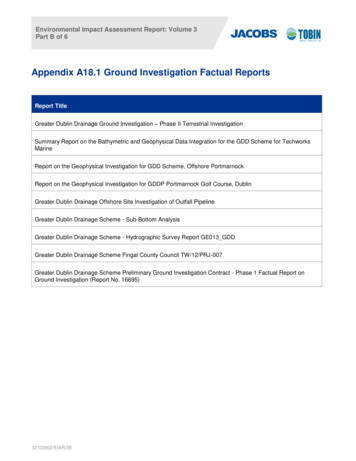
Appendix ASite and exploratory hole location plans
-8- ··- :c::: ::: : , - . !--1c. ., --PR .JECT:CLIENT:ENGINEER:Greater Dublin Drainage Scheme Ground InvestigationIrish WaterTobin Consulting EngineersKEY:TITLE:l 71· --- -.--71T-- -l --- - .r-:.-:. i:. ), .a., - Site location RIES:1 of 2DWG No:14-645-SL-001
British Standards Institute (2010) BS 5930:1999 A2: 2010, Code of practice for site investigations. Incorporating Amendment Nos. 1 and 2, as partially replaced by: BS EN 1997-2:2007: Eurocode 7. Geotechnical design. Ground investigation and testing BS EN ISO 22475-1:2006: Geotechnical investigation and testing.