Transcription
GEOTECHNICAL REPORTGEOTECHNICAL REPORT FORTHE EXPANSION OF POND 30Permanente Quarry, Lehigh Hanson SouthwestCementSubmitted To: Lehigh Hanson Southwest Cement24001 Stevens Creek BoulevardCupertino, CA 95014Submitted By: Golder Associates Inc.425 Lakeside DriveSunnyvale, CA 94085 USADistribution:Lehigh Hanson (PDF e-file)February 2015A world ofcapabilitiesdelivered locallyGolder, Golder Associates and the GA globe design are trademarks of Golder Associates CorporationProject No. 1417878
February 2015iProject No. 1417878Table of Contents1.0INTRODUCTION. 12.0SITE SETTING AND GEOLOGIC CONDITIONS . 22.1Topography . 22.2Regional Geologic Setting. 22.3Seismic Setting. 32.3.1Structural and Tectonic Setting . 32.3.2Seismicity . 32.43.0Geologic Hazards . 4INVESTIGATION FOR POND 30 . 53.1Review of Aerial Photos . 53.2Golder Field Exploration and Subsurface Conditions . 53.3Laboratory Testing . 63.3.1Test Methods . 63.3.2Summary of Lab Test Results . 64.0SLOPE STABILITY ANALYSIS . 84.1Methodology . 84.1.1Static Analysis . 84.1.2Seismic Analysis . 84.1.3Critical Cross Section Analyzed . 84.2Material Parameters . 84.3Slope Stability under Static Conditions . 94.4Slope Stability under Seismic Conditions . 94.4.1Yield Coefficient for Seismic Slope Stability Analysis . 94.4.2Seismically Induced Permanent Slope Displacement . 105.0CONCLUSIONS AND RECOMMENDATIONS. 115.1Conclusions . 115.2General Recommendations . 116.0USE OF THIS REPORT. 137.0CLOSING . 148.0REFERENCES. 15List of TablesTable 1Table 2Summary of Material Parameters Used in the Stability AnalysesSummary of Static and Seismic Slope Stability Analyses ResultsList of FiguresFigure 1Location Maplehigh hanson pond-30 geotech-report final v1 wlf.docx
February 2015Figure 2Figure 3Figure 4Figure 5Figure 6Figure 7iiProject No. 1417878Conceptual Layout – Pond 30 ExpansionGeologic Map and Locations of Test BoringsGeologic Cross Section A-A′Results of Static Slope Stability Analysis, Trial Surface Terminating at the PondResults of Static Slope Stability Analysis, Surficial Trial Surface within Existing SlopeResults of Pseudo-Static Slope Stability Analysis to Estimate Yield AccelerationList of AppendicesAppendix AAppendix BAppendix CAppendix DAppendix EEstimation of PGA and Acceleration Spectra for Maximum Credible EarthquakeTest Boring LogsLaboratory Test ResultsSlope Stability Analysis ResultsEstimation of Seismically Induced Permanent Displacementlehigh hanson pond-30 geotech-report final v1 wlf.docx
February 20151.01Project No. 1417878INTRODUCTIONGolder Associates Inc. (Golder) is submitting this geotechnical report for the proposed expansion of Pond30 at Lehigh Hanson’s Permanente Quarry located in Cupertino, California (Figure 1).This reportsummarizes the results of our field investigation, laboratory testing, and slope stability analyses.The location of the proposed existing Pond 30 and the proposed grading for its expansion are shown inFigure 2. The pond is located along the southeast margin of the East Material Storage Area. Review ofhistorical aerial photos show that the proposed pond expansion site is located on a level bench graded forconstruction of industrial buildings associated with the former Kaiser Aluminum Plant. The buildings weredemolished in 2002, and the pad was used for an equipment lay-down and staging area, stockpile foraggregate materials, as well as for storm drainage management (i.e., existing pond 30 and associatedinlet channel). The expanded pond has a surface area of approximately 1.5 acres with a storage depthof approximately 13 feet. The pond will be constructed entirely in excavation below existing groundsurface. The approximate storage capacity of the pond is 7 ½ acre-feet. The conceptual design of thepond includes a geomembrane liner to prevent infiltration.lehigh hanson pond-30 geotech-report final v1 wlf.docx
February 20152.02Project No. 1417878SITE SETTING AND GEOLOGIC CONDITIONSThe following sections summarize the regional topographic, geologic, and seismic setting; and describethe specific geologic conditions in the area of Pond 30.2.1TopographyThe Permanente Quarry and Cement Plant are situated in the foothills of the rugged, northwest-trendingSanta Cruz Mountains segment of the California Coast Ranges. Topography in the area consists ofmoderately to steeply-sloped terrain with rounded ridges and drainages. Relief at the project site rangesfrom about 2000 feet along the higher ridge crests to less than 500 feet mean sea level (msl) along theeastern portions of Permanente Creek. Average natural slope angles are typically around 25 . Thesteepest natural slopes are on the order of 40 over smaller slope heights (100-200 feet) and generallycorrespond to limestone outcrops.At the Pond 30 expansion area, the topography is a flat and level bench (el. 560 feet amsl) created byexcavation of a cutslope to the north, and placement of fill along the outboard edge of the pad. The padwas graded to accommodate construction of the former Kaiser Aluminum plant in the 1940’s.Thebuilding were demolished in 2002. The pad is long and narrow ( 2500 feet long by 200 feet wide) andthe alignment of the pad is parallel to the alignment of Permanente Creek.2.2Regional Geologic SettingThe majority of the subject property is underlain by complexly deformed and faulted rocks of theFranciscan Assemblage (Golder, 2011). The eastern portion of the site, is underlain in locations by PlioPleistocene rocks of the Santa Clara Formation. Overlying the bedrock are modern alluvial depositsassociated with Permanente Creek (restricted to the eastern portion of the property), and relativelyshallow surficial deposits comprised of soil and colluvium.The Santa Clara Formation overlies the Franciscan Assemblage rocks in the central and eastern portionof the property including the EMSA area where it occurs as remnant patches of terrane overlying theFranciscan Assemblage and is locally in fault contact along the Sargent Berrocal fault. (Golder, 2011).The Santa Clara Formation is a continental fluvial and alluvial deposit that is composed of unconsolidatedto slightly consolidated conglomerate, sandstone, siltstone, and claystone (Vanderhurst, 1981). Uplift ofthe Coast Ranges during this time resulted in increased erosion of the mountains and deposition of theSanta Clara Formation.The contact between the Franciscan rocks and Santa Clara Formation isconsidered to be unconformable, with the Santa Clara Formation deposited on an eroded Franciscanterrain (Rogers and Armstrong, 1973). Subsequent uplift of the nearby foothills along the Monte Vistafault, which lies along the margin of the valley floor to the east of the Quarry, has resulted in deformationof the Santa Clara Formation.lehigh hanson pond-30 geotech-report final v1 wlf.docx
February 20152.3Seismic Setting2.3.1Structural and Tectonic Setting3Project No. 1417878The San Andreas Fault zone is located approximately 2 miles southwest of the quarry (Golder, 2011).The Sargent-Berrocal Fault Zone (SBFZ), part of the Santa Cruz Mountains front-range thrust faultsystem, parallels the San Andreas to the east and forms the eastern-most structural boundary to thePermanente Terrain.Near the Permanente Site, the SBFZ consists of two northwest-trending, sub-parallel faults, namely thenortheastern-most Monta Vista Fault Zone and the southwestern-most Berrocal Fault Zone (Sorg andMcLaughlin, 1975). The combined fault zone is located in a complex contractional system of generallynortheastward-vergent thrust and reverse faults that bound the northeastern side of the Santa CruzMountains (McLaughlin and others, 1997). This thrust system has been described as an eastwardpropagating half-flower structure that roots toward the San Andreas fault zone.The Monte Vista strand of the fault zone is located approximately 800 feet to the northeast of theproposed Pond 30 expansion area. A strand of the Berrocal Fault Zone runs through the central portionof site and about 3100 feet west of the Pond 30 area (Sorg and McLaughlin, 1975). This fault forms astructural boundary between Franciscan basement rocks to the west, and Franciscan rocks overlain bySanta Clara formation rocks to the east. The Berrocal Fault Zone is not considered an active fault by theCalifornia Geologic Survey, it is classified as older than 1.6 million years (CGS, 2010).However,mapping of the Berrocal and Monte Vista faults following the 1989 Loma Prieta earthquake documentedminor distributed coseismic contractional deformation in the Cupertino foothills to the northeast of thePermanente site (Hitchcock, et al, 1994).2.3.2SeismicityThe Permanente Site is located within the San Francisco Bay Area, which is a region characterized byrelatively high seismicity. Golder evaluated potential seismic impacts for the project resulting from amaximum credible earthquake (MCE) on the San Andreas Fault. The MCE is defined as “the maximumearthquake that appears capable of occurring under the presently known tectonic framework.” The MCEwould be a moment magnitude (Mw) 8 event along the San Andreas Fault, which is assumed to be slightlyhigher than the Mw 7.9 San Francisco earthquake of 1906.lehigh hanson pond-30 geotech-report final v1 wlf.docx
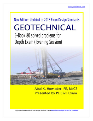
February 20154Project No. 1417878Golder estimated the peak groundacceleration(PGA)andtheacceleration spectra for the hipsdeveloped by Abrahamson and Silva(2008), Boore and Atkinson (2008),ChiouandYoungsCampbell and(2008),andBozorgnia (2008).The computed values from the fourrelationships were equally weighted(0.25 each) to estimate spectralaccelerationsasafunctionofmagnitude, source-to-site distance,and fault geometry and for anaverage shear wave velocity in theupper 30 meters (100 feet) of the soilcolumn (Vs30 ) equal to 760 meters per second (2,500 feet per second). The calculations are presentedin Appendix A. Golder estimates that the design PGA is 0.48g for the site. The median accelerationspectrum is included here for reference.2.4Geologic HazardsThe geologic hazards evaluated for the proposed project include the potential for ground rupture, slopeinstability, liquefaction and lateral spreading, consolidation settlement, and potential flooding associatedwith the proposed project. The geologic hazards that could impact the proposed pond expansion arelimited to ground shaking and slope instability.The risk associated with ground rupture is considered negligible since the project site is not situated on aknown Holocene fault.Liquefaction is not considered a hazard because of the presence of significantfines (silts and clays) in the soil underlying the proposed project site, and the relatively shallow depth tobedrock. Consolidation settlement is not considered a risk since the pond will be excavated and thereforethe site will be unloaded and not subject to induced settlement. The site is located approximately 35 feetabove the 100-year flood plain for Permanente Creek and therefore the risk associated with flooding isconsidered low. Tsunami and Seiche are not hazards due to the site location and elevation.Slope instability, and the relative risk to the project, is discussed in more detail in Section 4.lehigh hanson pond-30 geotech-report final v1 wlf.docx
February 20153.0INVESTIGATION FOR POND 303.1Review of Aerial Photos5Project No. 1417878A review of various stereoscopic aerial photographs and Google Earth images dating back to 1948 wasconducted to: (1) evaluate the past grading and development activities in the area, (2) prepare a geologicmap of surficial deposits and bedrock, and (3) identify any obvious signs of ground distress related toslope instability.The earliest set of aerial photographs (1948) show the Kaiser Aluminum buildings present on a gradedpad.There are three buildings in the general area of the proposed Pond 30 expansion. There isrelatively tall cutslope visible behind the northern two buildings. There is earthwork and grading activitiesassociated with development of roads up to the buildings. The slope below the pad to the north, and thehillside above the buildings are covered with orchard and are native ground. Site conditions remainsimilar until late 2002 when the buildings were demolished and the land use changed to materialstockpiles and equipment lay down. No evidence of slope instability was observed in the hillside terrainabove or below the proposed pond expansion area.3.2Golder Field Exploration and Subsurface ConditionsOn January 8-9, 2015, Golder performed a subsurface exploration consisting of four test borings at theproposed Pond 30 expansion site. The test borings are designated as B-1, B-2, B-3, B-4, and B-Pilot,the locations of which are shown in Figure 3.The borings were advanced with a truck-mounted, CME 85 drill rig turning a continuous flight, 8-inchdiameter, hollow-stem auger. During the drilling process, disturbed, but representative, soil samples wereobtained at 5-foot intervals. The samples were obtained by using a 1.5-inch (ID) Standard PenetrationSampler and a California Modified Sampler driven by a 140-pound hammer falling freely for 30-inches.The number of hammer blows required to drive the sampler 18-inches were recorded in 6-inch intervals.The number of blows required to drive the sampler the final 12-inches is designated as the penetrationresistance or “blow count.” The blow counts as recorded in the field are presented on the boring logs.The samples were retained in 1.5-inch and 2.5-inch diameter by 6-inch long brass tubes contained withinthe sampler. The samples were visually classified in the field by a geologist working under the directionof a California Professional Geologist (PG). The samples were retained in the tubes, placed in a sealedplastic bag inside a cooler, and transported to our office for sample review and selection of samples forlaboratory testing.All samples were classified in accordance to the Unified Soil Classification System. Pertinent informationincluding depths, stratigraphy, soil engineering characteristics, and groundwater occurrence werelehigh hanson pond-30 geotech-report final v1 wlf.docx
February 20156Project No. 1417878recorded. Stratigraphic contacts indicated on the logs represent approximate boundaries between soiltypes. The soil and groundwater conditions are those recorded for the dates indicated, and may notnecessarily represent those of other times or locations.Test borings B-1 and B-2 were extended to depths of 26.5 below ground surface (bgs) and B-3 and B-4were drilled to 20 feet bgs. B-Pilot was drilled first to establish the general subsurface conditions anddepth to bedrock. Representative bulk samples were obtained from this boring. Borings B-1 through B-4were sampled using standard geotechnical procedures with Standard Penetration Test (SPT) drivesamples and California Modified samples alternating every five feet.The B-Pilot boring encountered highly weathered greenstone bedrock at approximately 30 feet belowground surface. Water was encountered at approximately 18 – 20 feet below ground surface althoughthis water was possibly perched in this location. The upper four to five feet of the soil profile wasdescribed as Clayey Gravel (GW) and was interpreted as artificial fill.The remaining profile wasdescribed as Clayey Sand (SC) with gravel comprised of well graded, subrounded sand and gravel withiron oxidation. The material was compact and moist. This material is interpreted as colluvium overlyingheavily weathered greenstone although it may be a mixture of artificial fill and colluvium as these earthmaterials are very similar in appearance and composition.The remaining borings encountered the same general stratigraphic profile with minor variations in theinterpreted depth of fill ranging up to about seven to eight feet in thickness. Bedrock was encountered atapproximately 15 feet in Boring B-4. Groundwater was encountered at approximately 26 feet in Boring B2. Logs of the test borings are included in Appendix B.3.3Laboratory Testing3.3.1Test MethodsSelected soil samples were transported to Cooper Testing Laboratories in Palo Alto, California for furtherclassification and geotechnical testing. This testing included the following: Particle Size Analyses (ASTM D422) Atterberg Limits (ASTM D4318) Modified Proctor test (ASTM D1557) Direct shear test (ASTM D3080)Laboratory test results are included in Appendix C.3.3.2Summary of Lab Test ResultsThe above laboratory tests were performed mainly on the colluvium samples. The colluvium classifiesgenerally as Lean Clayey SAND with Gravel. The particle size analysis on a composite sample fromlehigh hanson pond-30 geotech-report final v1 wlf.docx
February 20157Project No. 1417878depth 3 to 25 feet from test boring B-1 shows 19.9% gravel, 48% sand, and 32.1% fines. The modifiedProctor test on this sample shows a maximum dry density of 135.8 pounds per cubic foot (pcf) and anoptimum moisture content of 8.1%.The four Atterberg limit tests performed on four samples from various depths of the four borings show lowplasticity with the liquid limit (LL) ranging from 28 to 37, the plastic limit (PL) ranging from 13 to 19, andthe plasticity index (PI) ranging from 14 to 18.The three consolidated drained direct shear strength tests show significantly large effective friction anglesfor the colluvium likely due to the presence of gravel. Because of the small size of the shear box relativeto the size of the gravels, the measured shear strength appears to be affected by the gravel. Therefore,the direct shear test results are considered unconservative for the project.lehigh hanson pond-30 geotech-report final v1 wlf.docx
February 20154.0SLOPE STABILITY ANALYSIS4.1Methodology4.1.1Static Analysis8Project No. 1417878The computer program SLOPE/W (2012 version) which uses two-dimensional, limit equilibrium method,was used to compute the factors of safety (FS) against potential slope failure at the site.This programallows both circular and noncircular sliding surfaces to be either defined manually or generatedautomatically to search for the lowest FS values. The Morgenstern-Price method was used to computefactors of safety.Based on traditional geotechnical practice, a minimum FS of 1.5 is considered acceptable under staticconditions.4.1.2Seismic AnalysisGolder performed a rigorous seismic slope stability analysis which included estimation of yield coefficientfor the slope and estimating the seismically induced permanent displacement using a predictive modeldeveloped by Bray and Travasarou (2007). The yield coefficient is the seismic coefficient that results inpseudo-static FS of 1.Based on the sate-of-practice for seismic design of earthen slopes (Duncan and Wright, 2005), 3 feet isconsidered as the maximum allowable permanent of displacement during the MCE event.To beconservative, a seismically induces permanent displacement of 1 foot (12 inches) is assumed as themaximum allowable limit in this report.4.1.3Critical Cross Section AnalyzedBased on a review of the topography of the site and interpreted subsurface conditions at the Pod 30 site,Golder identified the most critical cross section (A-A′) to analyze for stability of exiting slopes adjacent tothe pond expansion. The location of this cross section is shown Figure 3. The geologic profile alongcross section A-A′ is shown in Figure 4.4.2Material ParametersAs shown in Figure 4, the subsurface profile along cross section A-A′ consists of waste rock/artificial fill,fill/colluvium, and greenstone.The shear strength parameters for waste rock and greenstone wereselected based on Golder’s previous slope stability analyses for the East Material Storage Area inAppendix 11 of Golder (2011). For the fill/colluvium, Golder has assumed a conservative friction angle of28 degrees, based on the type of materials encounters (i.e., Lean Clayey SAND with Gravel) and ourengineering judgment. Table 1 below summarizes the parameters used in the slope stability analyses.lehigh hanson pond-30 geotech-report final v1 wlf.docx
February 20159Project No. 1417878Table 1: Summary of Material Parameters used in the Slope Stability AnalysesUnit Weight(pcf)Material1Waste Rock/Artificial FillFill/ColluviumGreenstoneNotes:4.3211Based on Golder (2011)2Conservatively assumed valueShear Strength ParametersCohesion(psf)Friction Angle(degrees)0351200281651,44023125Slope Stability under Static ConditionsThe slope stability analysis was performed for two conditions using the SLOPE/W computer program.Because the pond will be lined with a geomembrane, the analyses assume that there would begroundwater recharge from the pond and would not raise the water table level or lead to seepage forceson the existing slopes located to the west of the pond.The first slope stability condition analyzed is the potential for deep-seated slope failure surfaces thatinitiate near the toe of existing slope located to the west of the pond and terminating at the pond. Theresult of this analysis is shown in Figure 5. The analysis shows a FS of 1.82, which is greater than theminimum acceptable value of 1.5.The second condition analyzed the potential for surficial sloughing of the relatively steep existing slopeslocated to the west of the pond. The result of this analysis is shown in Figure 6, which shows anacceptable FS of 1.54.The results of SLOPE/W analyses are presented in Appendix D.4.4Slope Stability under Seismic Conditions4.4.1Yield Coefficient for Seismic Slope Stability AnalysisThe yield coefficient (or yield accelerations) for each of the two conditions discussed in Section 4.3 wereestimated from an iterative pseudo-static slope stability analysis using SLOPE/W by varying the inputseismic coefficient. The result of the final iteration for deep-seated slope failure surfaces in shown isFigure 7, which shows an yield coefficient of 0.215g (where, g is the acceleration due to gravity).Similarly, the result of the final iteration for surficial sloughing is shown in Figure 8, which shows a yieldcoefficient of 0.17g.lehigh hanson pond-30 geotech-report final v1 wlf.docx
February 201510Project No. 1417878The results of pseudo-static slope stability analyses are also presented in Appendix D.4.4.2Seismically Induced Permanent Slope DisplacementThe likely magnitude of permanent displacement was estimated using the Bray and Travasarou (2007)method.The permanent displacement calculations are presented in Appendix E. The calculations fordeep-seated failure surface estimated a permeant displacement of 9.3 inches during the magnitude 8MCE. Similarly, for surficial sloughing, the estimated permanent displacement is 4.3 inches. Both ofthese values are less than the allowable limit of 12 inches discussed in Section 4.1.2.Table 2 below presents a summary of the static and seismic slope stability analyses.Table 2: Summary of Static and Seismic Slope Stability Analyses ResultsEstimated PermanentDisplacementCondition AnalyzedStatic FSYieldCoefficientDeep-Seated Failure1.820.215g9.3Surficial Sloughing1.540.170g4.3lehigh hanson pond-30 geotech-report final v1 wlf.docx(inches)
February 2015115.0CONCLUSIONS AND RECOMMENDATIONS5.1ConclusionsProject No. 1417878It is Golder’s opinion that the site is suitable for development of the proposed Pond 30 expansion project.The results of the static and seismic slope stability analyses discussed in this report show that theexpansion of Pond 30 will not adversely impact stability of the existing slopes either above or below theponds. For the pond expansion itself, the static slope stability analysis shows a factor of safety of greaterthan the acceptable minimum values of 1.5 for a slip circle intercepting the pond liner. Similarly, theseismic slope stability analyses estimated seismically induced permanent displacement of less than themaximum allowable limit of 12 inches.Based on the encountered soil types and relatively shallow depth to bedrock, there is a low risk ofpotential liquefaction.The site is situated approximately 35 feet above the 100-year flood plain forPermanente Creek so there is a low risk of flooding. Although currently deeper, there is the potential thatgroundwater could rise to the proposed depth of the pond excavation ( 20 feet) and should be accountedfor in the final design for the project with appropriate recommendations for underdrains.5.2General RecommendationsThe following provide general recommendations based on our investigation and the conceptual plan forthe project.Golder will provide more detailed geotechnical recommendations and specifications inconjunction with preparation of final designs and construction plans for the project as necessary. Construction Observation: All earthworks should be observed and tested by a qualifiedgeotechnical engineering company. Construction observation and testing services mayinclude, but not be limited to, foundation subgrade verification, and verification that theplacement and compaction of engineered fill complies with recommendations andspecifications. Site Preparation: Prior to excavation and placement of artificial fill, the project areashould be stripped to remove the existing vegetation. Golder anticipates that the depth ofstripping will be 4- to 6-inches or less. Stripped soils may be stockpiled for re-use asvegetative layer soils. Earthworks Grading: Site grading is anticipated to primarily consist of the excavation ofsite soils to create the pond expansion, with more limited placement of engineered fills toachieve desired site grades. The subgrade should be prepared to achieve a firm andunyielding condition. All exposed soil surfaces that will receive fill or pavements shouldbe moisture conditioned as needed and compacted prior to fill placement or surfacingapplication.Scarification of near-surface soils may be necessary for moistureconditioning, but in no case should scarification extend deeper than 12 inches. Soilshould be compacted to the densities provided in the specifications for the project.Care should be taken to avoid disturbing subgrade soils and foundation soils that willremain in place. Areas which become softened or disturbed during construction shouldbe moisture conditioned and recompacted or removed and replaced with properly placedlehigh hanson pond-30 geotech-report final v1 wlf.docx
February 201512Project No. 1417878and compacted structural fill. Prior to fill placement, fill subgrades should be proof-rolledwith a loaded water truck or dump truck to identify yielding conditions. Yielding soilsshould be moisture-conditioned and recompacted, or excavated and replaced withstructural fill. Fill Materials and Placement: Engineered fill derived from on-site sources may be used toconstruct the proposed site earthworks. Engineered Fill materials should consist of
Jan 13, 2015 · GEOTECHNICAL REPORT FOR THE EXPANSION OF POND 30. Permanente Quarry, Lehigh Hanson Southwest Cement . GEOTECHNICAL . Submitted To: Leh