Transcription
SUPERAOC-SIMLP-BAOC-SIMLP-B AOC-SIMLP-3AOC-SIMLP-3 USER'S GUIDERev. 1.1
AOC-SIMLP-B( )/AOC-SIMLP-3( ) User's GuideThe information in this User’s Guide has been carefully reviewed and is believed to be accurate.The vendor assumes no responsibility for any inaccuracies that may be contained in this document,makes no commitment to update or to keep current the information in this manual, or to notify anyperson or organization of the updates.Please Note: For the most up-to-date version of this manual, please see our website at www.supermicro.com.SUPERMICRO COMPUTER reserves the right to make changes to the product described in thismanual at any time and without notice. This product, including software, if any, and documentation may not, in whole or in part, be copied, photocopied, reproduced, translated or reduced to anymedium or machine without prior written consent.IN NO EVENT WILL SUPERMICRO COMPUTER BE LIABLE FOR DIRECT, INDIRECT, SPECIAL,INCIDENTAL, OR CONSEQUENTIAL DAMAGES ARISING FROM THE USE OR INABILITY TOUSE THIS PRODUCT OR DOCUMENTATION, EVEN IF ADVISED OF THE POSSIBILITY OFSUCH DAMAGES. IN PARTICULAR, THE VENDOR SHALL NOT HAVE LIABILITY FOR ANYHARDWARE, SOFTWARE, OR DATA STORED OR USED WITH THE PRODUCT, INCLUDING THECOSTS OF REPAIRING, REPLACING, INTEGRATING, INSTALLING OR RECOVERING SUCHHARDWARE, SOFTWARE, OR DATA.Any disputes arising between manufacturer and customer shall be governed by the laws of SantaClara County in the State of California, USA. The State of California, County of Santa Clara shallbe the exclusive venue for the resolution of any such disputes. Supermicro's total liability for allclaims will not exceed the price paid for the hardware product.WARNING: Handling of lead solder materials used in thisproduct may expose you to lead, a chemical known tothe State of California to cause birth defects and otherreproductive harm.Manual Revision: Rev. 1.1Release Date: July 17, 2012Unless you request and receive written permission from SUPER MICRO COMPUTER, Inc., youmay not copy any part of this document.Information in this document is subject to change without notice. Other products and companiesreferred to herein are trademarks or registered trademarks of their respective companies or markholders.Copyright 2012 by SUPER MICRO COMPUTER, INC.All rights reserved.Printed in the United States of America1-2
Chapter 1: IntroductionTable of ContentsChapter I: Introduction.1-41.1Overview. 1-41.2IPMI Version 2.0. 1-51.3 Product Features. 1-61.4 Checklist. 1-61.5 An important Note to the User. 1-61.6 Contacting Supermicro. 1-7Chapter 2: Technical Specifications and Software Installation. 2-12.1 AOC-SIMLP-B/SIMLP-B /SIMLP-3/SIMLP-3 Card Layout and Jumper .Locations . 2-12.2 Block Diagram. 2-32.3 Safety Guidelines. 2-4Chapter 3: Software Application and Usage. 3-13.1 Home Page. 3-33.2 Functions Listed On the Home Page. 3-53.2.1 Remote Control. 3-53.2.2 Virtual Media. 3-73.2.3 System Health.3-113.2.4 User Management. 3-173.2.5 KVM Settings. 3-213.2.6 Device Settings. 3-253.2.7 Maintenance. 3-383.3 Remote Console Main Page. 3-423.3.1 Remote Console Options. 3-43Chapter 4: Frequently Asked Questions. 4-11-3
AOC-SIMLP-B( )/AOC-SIMLP-3( ) User's GuideChapter 1IntroductionThis manual is written for system integrators, PC technicians andknowledgeable PC users who intend to integrate Supermicro's unique IPMI 2.0Management functionality with the capability of KVM-over-LAN into their systems.It provides detailed information for the application and use of the AOC-SIMLP-B/SIMLP-B /SIMLP-3/SIMLP-3 that supports remote access for system monitoring,diagnosis and management. With the most advanced technologies built-in, theAOC-SIMLP-B/SIMLP-B /SIMLP-3/SIMLP-3 offers a complete, efficient, and costeffective remote server management.1.1 OverviewThe AOC-SIMLP-B/SIMLP-B /SIMLP-3/SIMLP-3 is a highly efficient, highly compatible and easy-to-use IPMI card that allows the user to take advantage of BMC,a baseboard management controller installed on a server motherboard and theIPMIView, an IPMI-compliant management application software loaded in a PC, toprovide serial links between the main processor and other system components, allowing for network interfacing via remote access. With an independent Peppercon'sKIRA100 processor built-in, the AOC-SIMLP-B/SIMLP-B /SIMLP-3/SIMLP-3 provides the user a solution to ease the complex and expensive systems, allowing an administrator to access, monitor, diagnose and manage network interfacinganywhere, anytime.1.2 IPMI Version 2.0The AOC-SIMLP-B/SIMLP-B /SIMLP-3/SIMLP-3 supports the functionality of IPMIVersion 2.0. The key features include the following: Supports IPMI over LAN Supports Serial over LAN Supports KVM over LAN (*AOC-SIMLP-B , AOC-SIMLP-3 only) Supports Virtual Media over LAN Supports LAN Alerting-SNMP Trap Supports Event Log Offers OS (Operating System) Independency Provides remote Hardware Health Monitoring via IPMI. Key features includethe following: Temperature monitoring Fan speed monitoring1-4
Chapter 1: Introduction Voltage monitoring Power status monitoring, chassis intrusion monitoring Remote power control to power-on, power-off or reboot a system Remote access to text-based, graphic-based system information,including BIOS configurations and OS operation information (KVM) Remote management of utility/software applicationsProvides Network Management Security via remote access/console redirection. Key features include: User authentication enhancement Encryption support enhancement, allowing for password configuration security to protect sensitive data transferring via Serial overLAN1.3. Product Features(a) The AOC-SIMLP-B/SIMLP-B Series: (IPMI 2.0 with a DedicatedLAN) Low profile Form Factor (5.1" W x 2.7" H) (129.3 mm W x 68.8 mm H)Supports 2U systems and aboveSupports IPMI over LAN(b) The AOC-SIMLP-3/SIMLP-3 * Series: (IPMI 2.0 with a DedicatedLAN and the Intel 82541PI GLAN Controller) Low profile Form Factor (5.1" W x 2.7" H) (129.3 mm W x 68.8 mm H)Supports 2U systems and above (*AOC-SIMLP-3/AOC-SIMLP-3 only)Supports IPMI over LANIntel's 82541 PI Gigabit LAN Controller (with 3rd data LAN support)The AOC-SIMLP-3 supports KVM(c) Features Supported by Individual ModelsFeaturesDedicated LANfor IPMIYesSIMLP-BSIMLP-B YesYesSIMLP-3SIMLP-3 YesIntel 82541 PI forData --Yes
AOC-SIMLP-B( )/AOC-SIMLP-3( ) User's Guide1.4 CheckListIf your shipping package came with missing or damaged parts, please contactSupermicro's Tech. Support. Please refer to the following checklist whencontacting us.i. AOC-SIMLP-B/SIMLP-B /SIMLP-3/SIMLP-3 :ii. Brackets: One full-size bracket, one low-profile bracket and two screws,iii. CDR-SIMIPMI: One Installation CDiv. White Box with Correct Barcode Label (showing AOC-SIMLP-B/SIMLP-B /SIMLP-3/SIMLP-3 ).1.5 An Important Note to the UserThe drawings and pictures shown in this manual were based on the latest PCBRevision available at the time of publishing of the manual. The AOC-SIMLP-B/SIMLP-B /SIMLP-3/SIMLP-3 card you’ve received may or may not look exactlythe same as the graphics shown in the manual.1-6
Chapter 1: Introduction1.6 Contacting SupermicroHeadquartersAddress:Tel:Fax:Email:Web Site:SuperMicro Computer, Inc.980 Rock Ave.San Jose, CA 95131 U.S.A. 1 (408) 503-8000 1 (408) 503-8008marketing@supermicro.com (General Informaion)support@supermicro.com (Technical ail:SuperMicro Computer B.V.Het Sterrenbeeld 28, 5215 ML's-Hertogenbosch, The Netherlands 31 (0) 73-6400390 31 (0) 73-6416525sales@supermicro.nl (General Information)support@supermicro.nl (Technical Support)rma@supermicro.nl (Customer Support)Asia-PacificAddress:SuperMicro, Taiwan4F, No. 232-1 Liancheng RoadChung-Ho Dist., New Taipei City 235Taiwan, R.O.C.Tel:Fax:Web Site: 886-(2) 8226-3990 886-(2) icro.com.tw (Technical Support)Tel: 886-(2) 8226-5990 (Technical Support)1-7
AOC-SIMLP-B( )/AOC-SIMLP-3( ) User's GuideNotes1-8
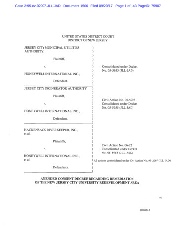
Chapter 2: Technical Specifications and InstallationChapter 2Technical Specifications and SoftwareInstallation2.1 AOC-SIMLP-B/SIMLP-B /SIMLP-3/SIMLP-3 CardLayout and Jumper LocationsAOC-SIMLP-B/SIMLP-B /SIMLP-3/SIMLP-3 CardLayout and Jumper Locations7849Front View1061253411112Front Components1. LAN Port 1 (JLAN1) for IPMI/Keyboard/Video/Mouse over IP2. LAN Port 2 (JLAN2) for 3rd Data via Intel's 82541PI Controller3. Intel's 82541PI GLAN Controller4. Peppercon's KIRA 100 Processor5/6. SDRAM (128Mb/133MHz)7. JP5: LAN Port1 Activity LED Jumper8. JP7: JLAN 2 Control Jumper9. JP6: GLAN Port2 Activity LED Jumper10. JP1: JLAN1 Control Jumper11. D3: Power-on LED12. D4: Heart-beat (Activity) LED2-1
AOC-SIMLP-B( )/AOC-SIMLP-3( ) User's GuideRear View12Rear Side Components1. Flash DRAM (64Mb/133MHz)2. VRAM (64Mb/166MHz)2-2
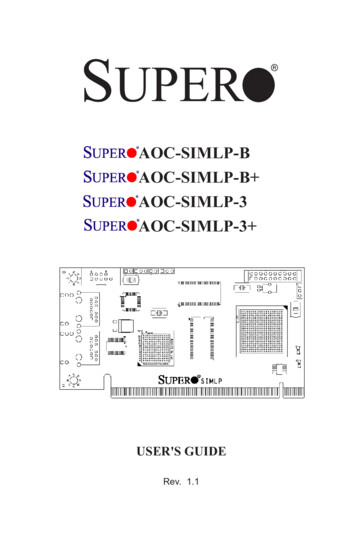
Chapter 2: Technical Specifications and Installation2.2 Block DiagramUARTPH2X10/-10IPMI-200 ConnectorsPCI-EETHERNETPHYUART InterfaceUSB InterfaceSupermicroFeatured GPIOKIRA100LPC InterfacePRSNT#FML InterfaceDVO VideoInterfaceRMIISMDATASMCLKSMALT#(IPMI may go to MBLAN)PCI x32Intel 82541PIGb LAN2-33rd LANDataLANIPMI & KVM
AOC-SIMLP-B( )/AOC-SIMLP-3( ) User's Guide2.3 Safety GuidelinesTo avoid personal injury and property damage, pleasecarefully follow all the safety steps listed below whenaccessing your system or handling the components:ESD Safety GuidelinesElectric Static Discharge (ESD) can damage electronic com ponents. To prevent damage to your system. it is important to handle it very carefully. The following measuresare generally sufficient to protect your equipment from ESD. Use a grounded wrist strap designed to prevent static discharge. Touch a grounded metal object before removing a component from the antistaticbag. Handle the IPMI card by its edges only; do not touch its components, peripheralchips, memory modules or gold contacts. When handling chips or modules, avoid touching their pins. Put the card and peripherals back into their antistatic bags when not in use.General Safety Guidelines Always disconnect power cables before installing or removing any componentsfrom the computer. Use only the correct type of bracket for the chassis. Please use a full-heightbracket for a 1U, 3U, 4U, Tower, or a Pedestal system. Use a low-profile bracketfor a 2U or some of the proprietary chassis. Make sure to secure the bracketin the host system cabinet. (*Note: When used in a 1U system, the full-heightbracket is mounted into the riser card.) Disconnect the power cable before removing the data cable from the risercard. Make sure that the IPMI card is securely seated in the PCI slot to preventdamage to the system due to power shortage.2-4
Chapter 3: Software Application and UsageChapter 3Software Application and UsageWith an independent I/O processor embedded in Raritan's Kira 100 RISC SystemChip, the AOC-SIMLP-B( )/SIMLP-3( ) Add-On Card allows the user to access,monitor, manage and interface with systems that are in remote locations viaLAN. The necessary utilities for the access and configuration of the add-on cardare included on the Supermicro bootable CDs that came with your card. Thissection provides information on the configuration and the access of the IPMIcard on the network.Using the IPMICFG Utility to Configure IP/MAC Addresses andother IPMI Network Settings1. Run the ipmicfg utility from the bootable CD that came with your shipment.2. Refer to the table below to configure the IP/MAC addresses.BoardX7 SeriesH8 DDR2 MEMORYIPMIMACIPSIMLPIPMI CardAvailable IP/DHCPSIMLPIPMI CardAvailable IP/DHCPCommunication ThruDedicated LANLAN1 on MBDedicated LANLAN1 on MB3. Follow the instructions given in the Readme.txt file to configure GatewayIP/Netmask IP addresses, to enable/disable DHCP and to configure other IPMIsettings.*Note: The Readme.txt file is included in the CD that came with your shipment.A copy of the Readme.txt file, dated 07/05/2007, is also included below.IPMICFG Version 1.04 Copyright 2007 SuperMicro Computer Inc.Usage: IPMICFG Parameters (Example: IPMICFG -m 192.168.1.123)-mShow IP and MAC-m IPSet IP (format: ###.###.###.###)-a MACSet MAC (format: ##:##:##:##:##:##)-kShow Subnet Mask-k MaskSet Subnet Mask (format: ###.###.###.###)-dhcp onEnable the DHCP-dhcp offDisable the DHCP-gShow Gateway IP-g IPSet Gateway IP (format: ###.###.###.###)To Access the SIM1U/SIM1U Card from a Computer1. Choose a computer that is connected to the same network and open thebrowser.2. Type in the IP address of each server that you want to connect in the addressbar in your browser.3. Once the connection is made, the Log In screen as shown on the next pagedisplays.3-1
AOC-SIMLP-B( )/AOC-SIMLP-3( ) User's GuideTo Log InOnce you are connected to the remote server, the following Log In screendisplays.1. Type in your Username in the "Username" box.2. Type in your Password in the "Password" box and click on "Login."(*Note: The default username is ADMIN. The default password is ADMIN.)3. The Home Page will display as follows:3-2
Chapter 3: Software Application and Usage3.1 Home PageHomeRemote Console ScreenLogout421Function KeysConsole9356783.1.1 Buttons from the Home Page1Home: Click this icon to return to the Home Page.2Console: Click this icon to go to the Remote Console Screen.34Remote Console Screen: Displayed in the window is RemoteConsole Screen. Click on this window to go to the Remote ConsoleScreen.Logout: Click on this icon to log out.5Refresh: Click on this icon to refresh the screen of theremote console preview.6Power On: Click on this icon to power on the system of theremote host.7Power Down: Click on this icon to power down the systemof the remote host.8Reset: Click on this icon to reset the remote host.3-3
AOC-SIMLP-B( )/AOC-SIMLP-3( ) User's Guide3.1.2 Function Keys from the Home Page91234567Click on these function keys to use the functions as specified below.1. Remote Control: Click on this icon for remote accessand management of Video Console Redirection.2. Virtual Media: Click on this icon to use virtual remotemedia devices.3. System Health: Click on this icon to view and manage health monitoring for remote systems4. User Management: Click on this icon for User Management.5. KVM Settings: Click on this icon to configure keyboard, Video and mouse settings.6. Device Settings: Click on this icon to configuredevice settings.7. Maintenance: Click on this icon to access, diagnoseand manage hardware devices(*Note: Please see the next page for details on the functions specified above.)3-4
Chapter 3: Software Application and Usage3.2 Functions Listed on the Home Page3.2.1. Remote ControlClick on the icon of Remote Control to activate its submenus-KVM Console andRemote Power as listed below.a. KVM ConsoleClick on this item to configure keyboard, mouse or video settings for the remotehost.Remote Console Screen12341Explanation of FunctionsIn the Single/Synchronized Mouse Mode, this cursor indicates thesystem that is currently active. For the Double Mouse mode, this is thecursor for the remote host.2This second mouse cursor only appears in the Double Mouse Mode.This cursor represents the local mouse.3This icon indicates the availability of Keyboard and Mouse.4This icon indicates the number of networks (users) that are connectedvia Console Redirection. (The number of figure icons indicates thenumber of users connected.)3-5
AOC-SIMLP-B( )/AOC-SIMLP-3( ) User's Guideb. Remote PowerClick on this item to configure the power settings for Remote Console as shownbelow.Remote Power Screen123Explanation of Functions1Power On: Click on this icon to power on the remote host.2Power Down: Click on this icon to power down the remotehost.3Reset: Click on this icon to reset the remote host.3-6
Chapter 3: Software Application and Usage3.2.2. Virtual MediaClick on the Virtual Media icon on the Home Page to activate its submenus-FloppyDisk, CD-ROM, Drive Redirection and Options as listed below.a. Floppy diskFloppy Disk Screen2314567Explanation of FunctionsFloppy Disk: Click on this function key to upload the1data stored in the local floppy disk image to the remotehost.2Active Image (Drive1): This window displays the datathat has been uploaded to Drive 1 of the remote host.3Active Image (Drive2): This window displays the datathat has been uploaded to Drive 2 of the remote host.4567Floppy Image Upload: This option allows the user toupload the floppy image as "floppy" located in the remotehost. The floppy image uploaded shall be in the binaryformat with a maximum size of 1.44MB. It will be loadedto the Supermicro SIMLP card and will be emulated tothe host as a USB device.Virtual Drive: Select a drive in the remote host as adestination drive for you to upload your image data.Floppy Image File: Click on "Browse" to preview andselect the files that you wish to upload to the host driveselected.Upload: Once the correct file name appears in the box,click Upload to upload the floppy image to the drivespecified in the remote host.3-7
AOC-SIMLP-B( )/AOC-SIMLP-3( ) User's Guideb. CD-ROM ImageCD-ROM Image Screen23145678910Explanation of Functions1234CD-ROM image: Click on this function key to share datastored in your local CD-ROM drive with other users in theremote host through the Windows Share application viaUSB.Active Image (Drive1): This window displays the filename of the data currently active in host Drive 1.Active Image (Drive2): This window displays the filename of the data currently active in host Drive 2.Image on Windows Share: This option allows the userto configure Windows Share settings. It allows you todecide how you want to share the data stored in yourlocal CD-ROM with users in the remote host.5Virtual Drive: Specify the drive that you want to shareyour data with in the remote host.6Share Host: Key in the IP Address or the name of thesystem you wish to share data with via Windows Share.78910Share Name: Key in the name of the system you wishto share data with in the remote host.Path to Image: Key in the location of source files thatyou wish to share via Windows Share.User/Password (Optional): Key in the Username andpassword for the person to access the data that you wantto share and click "Set" to enter your selections.3-8
Chapter 3: Software Application and Usagec. Drive RedirectionDrive Redirection Screen23145678Explanation of FunctionsDrive Redirection: Click on this function key to make1local drives accessible for other users via consoleredirection. This function allows you to share your localdrives (Floppy, CD-ROM and HDDs) with users in theremote systems.2Active Image (Drive1): This window displays the filename of the data currently active in host Drive 1.3Active Image (Drive2): This window displays the filename of the data currently active in host Drive 2.45678Drive Redirection: Use this window to configure DriveRedirection settings.Disable Drive Redirection: Check the box to disableDrive Redirection. Once this function is disabled, localdrives will not be accessible for other users in remotehost.Force Read Only: Check this box to allow the datastored in local drives to be read in a remote system,but it cannot be overwritten to ensure data integrity andsystem security.Apply: Once you've configured your settings, click "Apply" to enter your settings.Reset Default: You can also key in your own settingvalues and re-set these values as "default" by clickingon this icon to reset the defaults.3-9
AOC-SIMLP-B( )/AOC-SIMLP-3( ) User's Guided. Virtual Media OptionsVirtual Media Options Screen241Explanation of Functions1234Options: Click on this function key to activate the VirtualMedia sub-menu.Virtual Media Options: Use this option to disable or enable USB MASS storage in the remote host. Check thisbox to disable the function of Virtual Media Options toprevent data stored in a local drive from being accessed,or uploaded by the user in the remote host. The defaultsetting is "enabled."Apply: Once you've checked the box, click "Apply" toenter this value.Reset to Defaults: If you want to set "Disabled" as thedefault setting for the item-Virtual Media Options, clickon this icon.3-10
Chapter 3: Software Application and Usage3.2.3. System HealthClick on the System Health icon on the Home Page to activate its submenus:Chassis Control, Monitor Sensor, System Event Log and Alert settings as listedbelow.System Health Screena. Chassis ControlChassis Control Screen21312Chassis ControlChassis Control: Click on this function key to access Health Monitoring information on the remote chassis. The items monitored include 1. Chassis Information 2.Power Control.Chassis Information:The following remote chassis information is included:*Power Is: This indicates if the system is on or off for the remote host.*Power On Counter: If power is on, then the counter indicates the length of timethe power has been turned on.*Last Restart Cause: This item states the reason why the host system is restartedif the system has been turned off.* Refresh: Click the Refresh button to update "Chassis Information" as shown inWindow 2.3-11
AOC-SIMLP-B( )/AOC-SIMLP-3( ) User's Guide3Power ControlThe following Power Control items are included:Refresh: Click on this icon to refresh the screen of theremote host.Power On: Click on this icon to power on the system forthe remote host.Power Down: Click on this icon to power down the systemfor the remote host.Power Cycle: Click on this icon to power down the systemfor the remote host and turn it back on later.Reset: Click on this icon to reset the remote console.3-12
Chapter 3: Software Application and Usageb. Monitor SensorsMonitor Sensors Screen11Monitoring Sensor: Click on this function key to display the following Health Monitoring Information shown in the following table:3-13
AOC-SIMLP-B( )/AOC-SIMLP-3( ) User's GuideHealth Monitoring Sensor Information on the Remote HostTemperature MonitoringVoltage MonitoringFan ControlPhysical SecurityModule/Board CPU0Internal E.Module/Board CPU1Internal E.Module/Board CPUOverheatCPU1 Temperature(Temp A, Temp B)CPU2 Temperature(Temp A, Temp B)System TemperatureCPU1 VCoreCPU2 VCore3.3V5V, 5VSB 12V, -12V1.5VVBATFan1/CPU FanFan2/CPU FanFan 3 – Fan 6Chassis IntrusionTemp A: CPU1 Core1 Temperature, Temp B: CPU1Core2 Temperature,Temp A: CPU2 Core1 Temperature, Temp B: CPU2Core2 Temperature,CPU1 Vcore: CPU1 Core VoltageCPU2 Vcore: CPU2 Core Voltage5VSB: 5V StandbyVBAT: Battery VoltageSystem Fans/Chassis FansWhen the CPU temperature exceeds this presettemperature, the overheat LED or alert will betriggered, the CPUs will slow down, the CPU fanswill be in the full speed mode.When the system temperature exceeds this presettemperature, the overheat LED or alert will betriggered, and the cooling fans will be in the fullspeed mode to prevent system overheat.Module/Board ThermalTrip3-14
Chapter 3: Software Application and Usagec. System Event LogSystem Event Log Screen11System Event Log: Click on this function key to display the System Health EventLog for the remote host system.3-15
AOC-SIMLP-B( )/AOC-SIMLP-3( ) User's Guided. Alert SettingsAlert Settings Screen23411Alert Settings: Click on this function key to activate the alert settings submenu forthe remote host system. The items monitored include: 1. Filter List, 2. Policy Listand 3. LAN Destination List3-16
Chapter 3: Software Application and Usage3.2.4. User ManagementClick on the User Management icon on the Home Page to activate its submenus:Change Password, Users & Group and Permissions as listed below.User Management Screen1a. Change Password34212User Management: Click on this icon to activate the User Management submenu.Once this submenu displays, you can access the New Password fields.Change Password: Click on this function key to access the New Password andConfirm New Password fields.3New Password: Key in your new password in the blank.4Confirm New Password: Key in your new password in the blank again and click"Apply" to confirm it.3-17
AOC-SIMLP-B( )/AOC-SIMLP-3( ) User's Guideb. Users & Groups-User Management and Group 81Users & Groups: Click on this icon to activate the Users & Groups submenu.2User Management: This window displays the user's information.3Existing users: Select an existing user for information updates. Once a user isselected, click on the "Lookup" icon on right to view user information.4New user name: Key in new user name in this field.5Full user name: Key in full user name in this field.67Password and Confirm Password: Type the user's password in the field and thentype the password again in the next field to confirm it. The password must be 4characters or longer.8Email Address: Key in the user's email address in the field. (*Optional)9Mobile Phone: Key in the user's mobile phone number in the field. (*Optional)10Group Membership: This field indicates the group that the user belongs to. Toselect a group, click on the group name on the "Not Member Of" window to selectit as shown in Window 111, then click on the backwards arrow shown on 12 to enterthe group name in the Group Membership field as shown in 10 . Reverse the procedure to remove the user from a group.3-18
Chapter 3: Software Application and Usage1415IPMI Privilege Level: Click on the arrow key on the right to activate the PrivilegeSelection menu. The IPMI Privilege Level contains five categories: No Access,User, Operator, Administrator and OEM.Create: Click on this button to enter a new user's or group information in the User/Group Management fields.16Modify: Click on this button to modify a user's or group information in the User/Group Management fields.17Copy: Click on this button to copy a user's or group information in the User/GroupManagement fields.Copy UserChoose an Existing User from the selection box. Enter a new user name in thefield "New User Name." Click on the "Copy" button and a new user with thename you've typed in will be created. The properties of the selected user will becopied to the new user.Copy GroupChoose an Existing group from the selection box. Enter a new group name inthe field "New Group Name." Click on the "Copy" button and a new group withthe name you've typed in will be created. The properties of the selected groupwill be copied to the new group.18Delete: Click on this button to delete a user's or group information in the User/Group Management fields.19Group Management: This window allows you to enter group information for betteruser management.3-19
AOC-SIMLP-B( )/AOC-SIMLP-3( ) User's Guidec. Permissions3245611Permissions: Click on this icon to activate the User/Group Permissions submenu.2Show Permissions for User/Group: click on the arrow on the right to activate theuser/group permissions selection menu.3Update: Click this icon to update permissions information.4Effective Permissions: This field indicates the actual permissions a user/grouphas.5User Permissions: This field indicates the actual permissions a user has.6Inherited Group Permission: This field indicates the permissions a user has dueto the fact that he or she belongs to a certain group.3-20
Chapter 3: Software Application and Usage3.2.5. KVM SettingsClick on the KVM Settings icon on the Home Page to activate its submenus: UserConsole and Keyboard/Mouse as listed below.a. User ConsoleKVM Settings: User Console2345678910111112131415161718192021223-21
AOC-SIMLP-B( )/AOC-SIMLP-3( ) User's Guidea. User Console1. User Console: Click on this icon to activate the User Console submenu.2. User Selection: This field allows you to decide which group the user belongsto. Click on the arrow on the right to activate the selection menu and highlight thename of the group to select it.3. Update: Once you've selected the group name, click on Update to save theselections.4. Transmission Encoding: This field allows the user to decide how (the video)data is transmitted between the local system and the remote host.5. Automatic Detection: Select this optio
iv. White Box with Correct Barcode Label (showing AOC-SIMLP-B/SIMLP-B / SIMLP-3/SIMLP-3 ). 1.5 An Important Note to the User The drawings and pictures shown in this manual were based on the latest PCB Revision available at the time of publishing of the manual. The AOC-SIMLP-B/ SIMLP-B /SIMLP-3/SIMLP-3 card you've received may or may not look .