Transcription
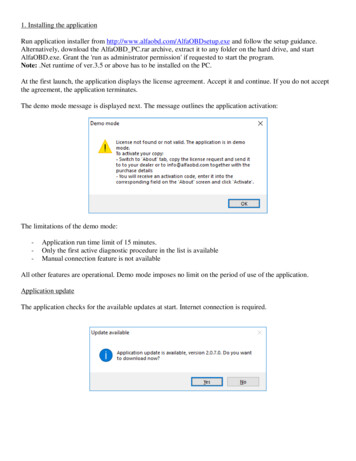
1. Installing the applicationRun application installer from http://www.alfaobd.com/AlfaOBDsetup.exe and follow the setup guidance.Alternatively, download the AlfaOBD PC.rar archive, extract it to any folder on the hard drive, and startAlfaOBD.exe. Grant the 'run as administrator permission' if requested to start the program.Note: .Net runtime of ver.3.5 or above has to be installed on the PC.At the first launch, the application displays the license agreement. Accept it and continue. If you do not acceptthe agreement, the application terminates.The demo mode message is displayed next. The message outlines the application activation:The limitations of the demo mode:-Application run time limit of 15 minutes.Only the first active diagnostic procedure in the list is availableManual connection feature is not availableAll other features are operational. Demo mode imposes no limit on the period of use of the application.Application updateThe application checks for the available updates at start. Internet connection is required.
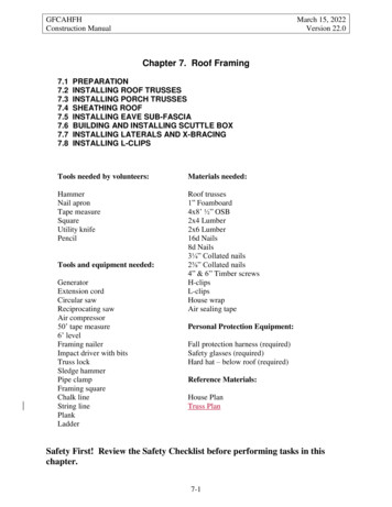
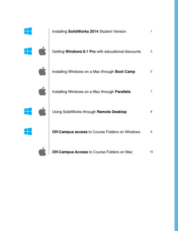
2. START tabSelect your car and the Electronic Control Unit you want to diagnose and click “Connect”. AlfaOBDautomatically detects the type and modification of the connected ECU. The connection status is reported in the“Status” line. If connection fails, a message is displayed with the information about possible causes of failure.
The application displays the adapter icon next to the ECU model and adds the adapter name to the ECU modeldescription when the adapter has to be connected between the interface and the car OBD plug:Additionally the "Connect adapter" warning is displayed before the application attempts to connect to the ECU:See http://www.alfaobd.com for more information about the adapters.Configuring the application settingsConfigure the general settings (COM port, OBD interface, etc.) at first use. To access the settings click the“Advanced mode”. To exit the settings screen click the “Regular mode”.
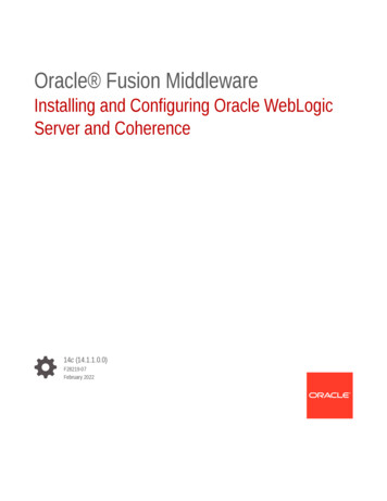
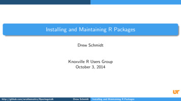
As an alternative to the selection in the regular mode, you can select electronic control unit (ECU) to connect toin the "Device" list. Each ECU in the list represents a group of modifications. The modification can beadditionally selected in the “Modification” box. The ECUs are grouped in the list according to their function.Note: The selection of the ECU and its modification done in the advanced mode is not reflected on the “Regularmode” screen.At the connect time, AlfaOBD automatically detects the ECU type and adjusts the ECU selection in the“Device” box and it’s modification in the “Modification” box. If the connected ECU is not currently supported,the application displays the "Wrong ISO" message. You can continue with the diagnostic, but the validity of thediagnostic results is not guaranteed. Use the "Send ISO to AlfaOBD" to request the support of the controlmodule in the future updates. To send the email from the message box you need to have an email clientconfigured on the PC.The OBD interface is selected in the "Interface" list box.
The following types of the OBD interfaces are compatible with the software: KLLine serial or USB. Only for the ECU with the diagnostic over the K-Line, no CAN supported.OBDKey Bluetooth, USB, and WLAN http://www.obdkey.com/vehiclediagnostics.asp. This interface isa universal one supporting all the listed ECUs, both the K-Line and CAN-based.ELM327-based Bluetooth, USB, and WLAN interface. There are many suppliers of such devices, makesure the version of the ELM327 chip is 1.3 and above. The interface supports all CAN and most of theK-Line units. A rule of thumb is the K-Line units with the connection baud rate less than 10400 bps arenot supported. An enhanced version of the ELM327 is the OBDProtect/OBDDirect interface.OBDLink SX/LX/MX/MX https://www.scantool.net . The limitations of the ELM327 interface apply.The advantage of the OBDLink is a high communication baud rate of 115200 bps.For the latest update on the interface support and the recommended interfaces, as well as the details of theinterface capability to support different units, see http://www.alfaobd.com .Select the available serial port in the "Port" box.If using the OBDKey or ELM327 interface the pair the Bluetooth unit with the PC first or install the drivers forthe USB interface. To view the available COM ports information, open the Windows Device Manager andcheck the “Ports” section.The "Baud rate" parameter has different meaning for the KLLine and OBDKey/ELM327 interfaces. Becausethe KLLine interface acts as the pass-through the baud rate set is the baud rate at which the PC connects to thecar ECU. In the case of the OBDKey/OBDLink/ELM327 interface the baud rate is set for the communicationbetween the PC and the interface, while the baud rate for the communication between the interface and the carECU is set automatically by AlfaOBD. For the KLLine interface the baud rate is configurable for the GenericKWP2000 or ISO9141 ECUs only, otherwise the baud rate is set automatically by the software. Typically, thebaud rate of 10400 bps is used for the KWP2000 and 4800 bps for the ISO9141 units. For the OBDKeyinterface the baud rate of communication between the PC and the interface is fixed at 9600 bps. For ELM327interface the default baud rate is set at 38400 bps, for the OBDLink interface the baud rate is set to 115200 bps.If the ELM327 USB/BT or OBDProtect/Direct interfaces selected, the application displays the "High speed"check box. Turn on the option for the program to try setting a higher communication speed to the interface thenthe default 38400 bps. If the interface supports the high communication speed, it will be employed by theapplication.If using the WLAN interface, you need to configure the WiFi connection to the interface first. Before startingthe communication session make sure that WiFi is on and the PC is connected to the interface network. See themanual supplied with the interface for WLAN connection details. Set the IP address and the IP port used by theinterface (see the interface manual for the required values).
The description of the other parameters found on the configuration tab:------The “KW2000 Init wait time” is relevant for the KLLine interface only. The parameter affectsinitialization of the KW2000-based units. If you see in the connection status line that the ‘fast init’connection fails, try to vary the parameter within the limits of 20-40 ms.The “ISO9141 Init wait time” is relevant for KLLine interface only. The parameter affects initializationof the ISO9141-based units. If you see in the connection status line that the ‘slow init’ connection fails,try to vary the parameter within the limits of 1-30 ms.The "Address" setting is only configurable for the Generic KWP2000 or ISO9141 ECUs, otherwise theaddress is set automatically by the software. If you know the address of a Generic KWP2000 orISO9141 ECU, select it in the "Address" list. The address value is in hexadecimal.The "Control Unit Timeout" parameter determines the maximum time AlfaOBD waits for the ECUresponse after sending the request, before timing out the connection.The “Interface Timeout” parameter is relevant to the OBDKey, ELM327, and OBDLink interfaces and itdetermines how long the interface waits for additional data after receiving a partial reply from the ECU.In general, keep this parameter as low as possible to speed up the communication. For the most of theunits, the default 100 ms is OK. If after the connection has been established the message popups that it’simpossible to verify the connected unit, try to increase/decrease this parameter and reconnect.The "Request Interbyte" is the time between the bytes in the request. This parameter can be the mostimportant one for the communication stability for the KW2000 and ISO9141 based ECU. Usually 4 - 6ms is the optimal setting for the KLLine and 2 ms for the OBDKey interface. Not applicable for theELM327/OBDLink interfaces and the ABS5.3 and engine Bosch ME3.7.1, M1.7/2.7, MA 1.7 controlunits.The "Interrequest time" parameter is logically connected with the "Response-Request". Thecommunication between the application and the ECU is serial, that means it proceeds as the series ofrequest - response cycles. After sending a request, AlfaOBD waits for a response from the ECU. Onlyafter receiving the response within the timeout limit, AlfaOBD can send the next request. Even if no
---requests has been made by AlfaOBD, it still has to keep sending the "Tester present" (or "Keep alive")requests, otherwise the connection is terminated by the ECU. The typical time of a complete requestresponse cycle is about 200ms. The "Response-Request" parameter determines the time between the endof the ECU response and the next request ("keep alive" or data request). Normally you can set thisparameter to zero but sometimes to improve the stability of communication it is recommended toincrease the value. The "Interrequest time" is the time between the consecutive requests; it varies from200ms to 60sec. Use a longer period when scanning for a slow changing data, like engine coolant orpassenger compartment temperature. If a high "Interrequest time" selected, AlfaOBD automaticallysends the "keep alive" messages to the ECU between the data requests to prevent the communicationtimeout. If the total "Response-Request" value plus the request-response cycle time are higher than the"Interrequest" value selected, the AlfaOBD built-in algorithm optimizes the communication timingconsidering also the timeout defined in the data exchange protocol specifications.The "KW71-Interbyte" is only applicable for the ABS5.3 and Bosch ME3.7.1, M1.7/2.7, MA 1.7 ECUs.The data exchange is different from the one described above, the communication proceeds byte-by-byte.The parameter defines the time between the moment when AlfaOBD receives a byte from the ECU andthe moment the application sends a byte to the ECU. The value of 5 ms is usually fine.The "X-scale" parameter influences the plotted data display. By default, a point on the X-axis of thegraph corresponds to a measurement. You can increase this ratio for plot readability.The "Use Blue adapter with OBDLink MX" option can be of help if the connection to a middle-speedCAN bus unit fails. Normally the OBDLink MX/MX interface can connect to the middle-speed CANbus units directly, without the adapter. Sometimes this direct connection is not successful, in this caseactivate the option and connect the Blue adapter.The "Record data" checkbox is for the support and debugging purposes only, activate it when AlfaOBDSoftware asks for the recorded data for the troubleshooting. AlfaOBD creates the AlfaOBD Debug.binfile in the Data subfolder of the application installation folder. Deactivate the option for the normalmode, because the recording of the debug data creates substantial overhead.The "Connect" button is self-explanatory and it is logically the first button to click after the configuration doneand the ECU selected. Please make sure that the ignition key is in the MAR/RUN position before attemptingthe connection. There are several exceptions to the “key in MAR/RUN” rule, some units have to be connectedto with the key in Stop or Lock positions, see the on-screen guidance.The application does several attempts to connect to the ECU trying different timing settings. If unsuccessful, theapplication switches to the "Idle" mode and displays a failure message.Hint: if communication is not established, turn the ignition key to Stop, wait for 30 sec then turn the key to theMAR/RUN and retry the connection. If using the OBDKey or ELM327 Bluetooth/USB interface, try to reset itby taking it out of the car OBD plug and inserting it back.Hint: On some cars (e.g. Alfa GTV) the connection to certain units (airbag, ABS) can only be established whenthe Code control unit is deactivated (the key is not recognized and the CODE light is on). To deactivate theCode control unit, disconnect the antenna plug at the Code control ECU.If the "Automatic reconnect" is activated the application automatically tries to re-connect when thecommunication breaks.The status of the communication is reflected in the status line on the top of the application window. After thecommunication has been established, you can proceed with reading fault codes, running active diagnostics, orscanning the sensor data at the next tabs.
The "Login with code card" controls are displayed for the relevant units only. Normally you can proceed withthe diagnostics without the login. You have to login with the Code Card when running certain active diagnosticsor the configuration procedures, see the on-screen guidance. For example, the login with the Code Card canhelp to turn on the engine when the immobilizer unit is faulty, which prevents the engine from starting. Connectto the corresponding engine control unit; enter the 5-digit code from the Code Card supplied with your car andclick the "Login with code card". The engine control unit does not provide any information whether the loginattempt is successful or not. Just try to start the car with the ignition key, but do not turn the key to the Stopposition while starting the engine, if done so repeat the login.If the control unit provide the information about the status of the login, the application displays it in the statusline.Note: the Steering lock unit (Alfa Romeo 159, Fiat Croma) accepts the login when the key is in the ‘Stop’position only.Note: if your Code Card has been lost or it not supplied with the car, contact your Fiat dealer for the code.For the Central Lock RF receiver unit (Alfa Romeo 156, Fiat Multipla, etc.) you need to login with thepassword before running certain diagnostic procedures. The password is not the same as the code from the CodeCard and it is not supplied with the car. Try to obtain it from your Fiat dealer. The Central Lock RF receiverdoes not provide any information whether login is successful, so AlfaOBD just displays a message about thestatus of the login attempt (accepted or rejected). If the entered password is incorrect, the correspondingconfiguration procedures will be rejected by the Central Lock RF receiver.You can save the code and the password to be entered automatically into the box in the future. Only one codeand one password can be saved. Be aware of the security risk, the procedure of login with the code card can beused to bypass the immobilizer!
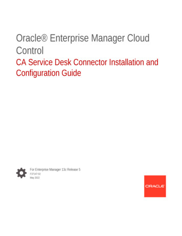
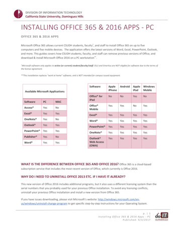
3. STATUS/FAULTS tabHere you can read faults stored by the ECU and monitor the "static" data reported by the ECU. The "static"means that the data does not change at all during the car life-time (car model, production year, etc.) or itchanges too slow to present it in the graphical mode (odometer, etc.)Click the "Read Faults" button. If the ECU stores any faults the application displays them in the "Fault Codes"box:To view the fault description click on the fault in the list:
To view the environmental data accompanying the particular fault (freeze-frame) click "More Info":Some units do not provide this additional data, in this case the "More Info" button is disabled.For certain units (airbags, Code Control, etc.) the list of the fault codes is not filled and all the available data isdisplayed in the "Fault description" window:Click "Clear faults" to erase the stored faults from the ECU memory. The engine must not be running.
Click “Read System ID” to display the control unit identification data (the drawing, hardware and softwarenumber, ISO code, programming date etc.)Click "Read system status" to view the "static" data from the ECU, the information displayed is the ECU-typedependent. Check the “Auto refresh” check box and click the "Read system status" to auto-update the datadisplayed.To save the faults and the system status data, check the "Save log" checkbox. AlfaOBD saves all the dataobtained in a text file which can be found in the Logs subfolder of the application installation folder. The nameof the file is ECU name Info.log, the file can be opened with a text editor.Note: Only the data received after the "Save log" checkbox activation is saved.When the ABS5.3 is selected, an additional check box "Keep ABS connection" is displayed. If it is checked,AlfaOBD repeatedly requests system status data from the ECU. If the check box is unchecked, AlfaOBD readsdata once and terminates the connection. The status of the check box does not have effect on reading the faults,AlfaOBD terminates the connection after having read them.Note: Connection to the ABS5.3 control unit can be established only if the car is stationary. The ECUterminates connection when the car speed exceeds 20 km/h.
For particular ECUs it is possible to monitor selected parameters.Check the “Monitor parameters” check box and select the parameters to monitor. AlfaOBD automatically startsscanning the selected parameters (if connected to the ECU).
To turn off the scanning deselect parameters or uncheck the “Monitor parameters” box.Starting from ver. 1.5.9 it is possible to monitor the fault codes. Check the “Monitor faults” box and click “Readall faults”. AlfaOBD repeatedly requests the ECU for the fault codes. Activate “Save log” to be able todetermine the moment when a new fault code is registered.Note: some parameters might not be relevant depending on the car configuration. In this case, “No data” or justnothing is displayed as the parameter value.4. ACTIVE DIAG tabActive diagnostics of various devices installed on the car is available here. PLEASE READ CAREFULLY anyon-screen instructions before running any procedure, some of the procedures have irreversible effect!For most of the procedures it is important that engine is NOT running (but the key is in MAR/RUN), this isexpected by default. For the procedures for which it is essential that the engine is running, it is specificallynoted in the on-screen guidance.The list of available procedures is ECU-modification dependent. Only the procedures common to all the devicesin the selected ECU group are displayed in the "Idle" state (when no connection is established). To protect yourcar from performing a wrong procedure, AlfaOBD adds the procedures relevant for the detected ECUmodification to the diagnostic list after the connection to the ECU has been established and the ECU has beenverified.Follow the on-screen guidance to perform the procedures. For some of the procedures certain conditions,additional checks, steps, or data entry are necessary, just follow the guidance.
To start the procedure select it in the list and click "Start". Usually the active diagnostic procedures last 5 - 10seconds and involve activation of certain devices (lamps blinking, valves and relays ticking, fans rotating etc.).You can stop the procedure by clicking "Stop". Although, some procedures once started cannot be stopped.AlfaOBD displays the corresponding messages related to the procedure state.Some procedures require certain preconditions (the coolant temperature, engine rpm, etc.) to be met. In some(most important) cases AlfaOBD checks the preconditions and prevents the procedure from starting if thepreconditions are not met. In any case you should always check the preconditions before running the procedure.If necessary switch to the "Status" or "Plotted Data" tabs to check the values of the parameters mentioned in theprocedure description.The results of the procedure is displayed by AlfaOBD on the "Active Diag" screen, sometimes you will have toswitch to the "Status" or "Plotted Data" screen to control the parameter(s) affected by the procedure that wasjust performed.5. PLOTTED DATA tabHere the "dynamic" data is displayed in graphical form. The set of parameters is ECU-dependent, but generally,it is not ECU modification-dependent. Because of that for some of the ECUs in the selected group certainparameters can be unsupported (the corresponding gauge will be blank). To scan the data, select the desiredmeters by clicking on them and choose "Meters" - "Activate" - "Activate selected" (or right-click to callcontext menu and choose "Activate selected"), then click "Start scan". Alternatively, the meters can beactivated/deactivated by a double-click. You can activate/deactivate all the meters, or all the meters on thecurrent tab. Because the communication is serial, the more meters are activated the longer is the period betweenthe successive measurements for each meter. The scan rate also depends on the "Interrequest time" parametervalue.The last measured parameter value (black) and the minimum (blue) and the maximum (red) values are displayedto the right of each meter.
The number of the last measurements stored is determined by the screen width, the maximal number is set for600. You can save a "snapshot" of the current data by clicking "Data" - "Save". Data is saved in binary form tothe Data subfolder of the application installation folder. To load previously saved data, click "Data" - "Load".The explorer window is displayed with all the saved snapshots available for the current ECU. The names of thesnapshots reflect the date/time when the data was saved (be aware that, for example, if you save the datacollected yesterday, the snapshot name has today's attributes) and ECU selected:MMDDYYYY hhmm. ECU , where MM - month, DD - day, YYYY - year, hh - hour, mm - minutes, ECU - current ECU name. Select a snapshot from the list and click "Open". Warning: the current data is deleted!You can move the selected meter up and down within the currently selected tab or move it to a different tab.You can use these features to rearrange the meters by a common function or use and scan them as a group forthe data comparison. If you want to move a meter take care that only this particular meter is selected, otherwiseAlfaOBD displays the message "please select single meter". (Hint: if you have selected several meters ondifferent tabs, you can deselect all of them by clicking "Meters" - "Deselect" - "All" or "Deselect all" fromthe context menu). Select a meter and choose "Meters" - "Move up", "Move down", or "Move to tab"- "TabN". The maximum number of the meters on a tab is 7.You can zoom one or several meters on each tab by selecting the meters and clicking "Zoom" - "Zoomselected meters". The data for the selected meters is plotted at the same graph which can be convenient for thedata comparison.For example, to check whether the clutch is slipping (for a Selespeed ECU) move the "Engine rpm" and "Clutchdisk speed" meters to the same tab, activate and zoom them, start the scan and drive the car for some time. If theclutch speed is lower than the engine speed for non-idle, the clutch can be slipping and considered for thereplacement.You can have the zoomed and normal modes on different tabs at the same time. You can increase or decrease xscale both in the normal and zoom modes by clicking "Zoom"- "Increase x-scale" or "Decrease x-scale" (or
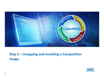
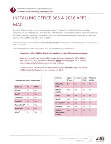
use the context menu). The data display gets "wide" or "narrow" correspondingly. In the zoom mode it isadditionally possible to shift the graph left or right to view different parts of the graph. Click "Zoom" - "Resetto default" to return to the default zoom value set at the Start screen.To store all the data scanned in a csv-file, start the data recording by clicking "Data" - "Record". The file isstored in the Logs subfolder of the application installation folder, the file is named ECU .log, where ECU is the current ECU name. The following data is stored in the file: the Meter name, Time (with millisecondprecision), Value. The data is appended to the file each time the recording is started, so the file can consist ofmany "chapters" and it will grow large with time. The file is optimized for viewing in MS Excel.To stop the data recording click "Data" - "Stop Recording".Here is an example graph:
6. MANUAL CONNECT tabThis screen is a kind of communication terminal and can be of use for advanced users. The communicationbetween AlfaOBD and selected ECU is displayed in a raw format here. You can send commands to theinterface (if using OBDKey/ELM327) and/or to the ECU.Be careful when using this functionality, you can damage the car by sending a wrong command!First, start the communication by choosing init mode and click "Init". Typically, KWP2000-based ECUssupport fast and slow init, ISO9141-based ones only support slow init. "Fast 200" and "Fast 10400" options areonly relevant for a KLLine interface, any of these options can be chosen for OBDKey or ELM327 interface.The difference between these options is that for the first one the init procedure includes switching the baud rateto 200bps first and than to 10400bps, while the second one uses 10400bps throughout the init. ISO9141-basedunits are not supported by ELM327 interface. For the CAN-based units choose a corresponding BCAN orCCAN init.The "Tester present" check box controls whether the "keep alive" messages are sent to the ECU after thecommunication has been established. If it is checked the “keep alives” are sent. If it is unchecked, theestablished communication is not automatically kept and it times out eventually.The "Response Off" check box controls the display of the ECU response to "keep alive" messages. If it ischecked, no response to "keep alive" is displayed.The "Echo On" controls display of the echo received from the interface (mostly related to the KLLine). If thebox is checked the echo is displayed together with the ECU response.The "Clear terminal" clears content of the Terminal window.
The "Char" and "Hex" options control how the data exchange is interpreted in the "Terminal" window, and inthe "Send command" box. If the "Hex" is checked, the data is displayed in the hexadecimal form as it isreceived by the software. This option generally should be selected for the KLLine interface. If the "Char" optionis selected, the data is displayed in the ASCII form, which is relevant for the OBDKey interface.Enter the commands to send to the ECU and the interface in the "Send command" box.WARNING: you must know exactly what to send to avoid damage to the car!To get a hint for using this functionality, click "Send" with the "Send command" box empty:The "Read Faults" and "Clear Faults" buttons suggest the commands to send to ECU to read and clear faultscorrespondingly. Suggestions are done considering the selected ECU group. The commands displayed in the"Send command" box do not include header and CRC bytes defined by the communication protocol. To sendthe commands in a correct form do not clear the "Header" and "CRC byte" check boxes. The ECU responses tothe commands will be displayed "as is" in the "Terminal" window, so you need knowledge of thecommunication protocol to interpret them.Generally, you do not need to clear the "Header" and "CRC byte" check boxes, because AlfaOBD automaticallycalculates the header and CRC for you depending on the chosen ECU. If you clear the checkboxes, you have toadd the header bytes and the checksum byte yourself to the command to send.Click the "Disconnect" to terminate the connection.The "Close Port" button closes and opens the selected communication port.
7. ABOUT tabIf the application is in the demo mode, you can find the license request code here:Click the "Send activation request" to send the activation request to info@alfaobd.com. A new email message iscreated with the activation request in the email text. An email client has to be configured on the PC for thisfeature to function correctly. After receiving the activation code from info@alafobd.com paste it to thecorresponding filed on the screen and click “Activate”.
in the "Device" list. Each ECU in the list represents a group of modifications. The modification can be additionally selected in the "Modification" box. The ECUs are grouped in the list according to their function. Note: The selection of the ECU and its modification done in the advanced mode is not reflected on the "Regular mode" screen.