Transcription
GFCAHFHConstruction ManualMarch 15, 2022Version 22.0Chapter 7. Roof NG ROOF TRUSSESINSTALLING PORCH TRUSSESSHEATHING ROOFINSTALLING EAVE SUB-FASCIABUILDING AND INSTALLING SCUTTLE BOXINSTALLING LATERALS AND X-BRACINGINSTALLING L-CLIPSTools needed by volunteers:Materials needed:HammerNail apronTape measureSquareUtility knifePencilRoof trusses1” Foamboard4x8’ ½” OSB2x4 Lumber2x6 Lumber16d Nails8d Nails3¼” Collated nails2⅜” Collated nails4” & 6” Timber screwsH-clipsL-clipsHouse wrapAir sealing tapeTools and equipment needed:GeneratorExtension cordCircular sawReciprocating sawAir compressor50’ tape measure6’ levelFraming nailerImpact driver with bitsTruss lockSledge hammerPipe clampFraming squareChalk lineString linePlankLadderPersonal Protection Equipment:Fall protection harness (required)Safety glasses (required)Hard hat – below roof (required)Reference Materials:House PlanTruss PlanSafety First! Review the Safety Checklist before performing tasks in thischapter.7-1
GFCAHFHConstruction Manual7.1.March 15, 2022Version 22.0PREPARATION7.1.1. Installing Planks and Gable End Blocking1.Install a plank along the center of the house for the center truss installer to walk astrusses are installed. The plank is installed on top of interior door headers and otherbracing as required. This is a 24’ plank that starts at one end of the house and will bemoved to the other end as the truss installation progresses. The plank needs to besupported at three points in either location.2.Install 2x6 blocking along the top of both gable end walls (continuous along theentire length) with 16d (or 3¼” collated) nails staggered every 12”. Hold the 2x6back 1” from the outside of the top plate (using a piece of 1” foamboard as a guideworks well). The 2x6 overhangs the plate on the interior side of the wall and servesas sheetrock blocking.3.Install 2x4 blocking along the top of the porch gable end framing, holding theblocking 2” back from the outside face of the framing. Nail with 16d (or 3¼”collated) nails staggered every 12”.7.1.2. Gable End Truss Prep7.1.2.1. Building Gable Ladders1.The steps that follow describe building a ladder to form gable roof overhangs. A“ladder” is built using 2x6s. The sub-fascia is the “outside” leg of the ladder,another 2x6 is the inside leg, and 2x6 blocks 6” long are used as rungs.2.Measure from the peak of each gable end truss to the tail. This is the total lengthof the sub-fascia. Check the roof pitch on the House Plan (the garage roof pitchmay not be the same as the house roof pitch). Cut long 2x6 pieces for the SUBFASCIA to match the length and angle (4/12 pitch 18.4 ; 5/12 pitch 22.5 ;6/12 pitch 26.6 ) of the top chord of the gable truss and mark them forlocation. DO NOT use material with a pronounced crown. If two pieces of 2x6are needed, make sure to seam the two pieces, with a butt joint, in the middle of adouble sub-fascia spacer block.3.For both gable end trusses, and the porch gable truss (if required) - cut INSIDE2x6s to match the sub-fascia length above less 32”, with an angle cut on the peakend to match the roof pitch. These pieces will go against the truss OSB once theladder is completed. Lay the inside 2x6 on a corresponding sub-fascia 2x6, withthe angled ends and top edges flush. From the peak of the matched angle cuts,measure and mark the top edges of the 2x6s for sub-fascia spacer blocks. Thefirst mark is at 5” and then every 32”, with the last one flush with the square endof the inside 2x6 (not necessarily at 32”). At each mark, put an X on the edge ofthe 2x6 toward the eave end. Make a mark for a double block (if required)where the butt joint of the 2x6 sub-fascia will be located.7-2
GFCAHFHConstruction ManualMarch 15, 2022Version 22.04.Count the number of marks made on all three trusses. Cut that many 2x6x6”sub-fascia spacer blocks (using scrap).5.For each gable end truss, assemble the blocks and inside 2x6s from Steps 2through 4 above. Align one end of the block with the layout mark and flush withthe edges of the inside 2x6. Nail together using two 3¼” collated nails throughthe long inside 2x6 into the end of each block (similar to building a stud wall).NOTE: Each gable requires a right and a left hand “ladder”; be sure toassemble each “ladder” with the inside 2x6 arranged in thecorrect orientation.6.Set the partially assembled ladder aside until the gable ends are covered withfoam. Finish installing the ladders in Section 7.1.2.2.4, below.7.1.2.2. Gable Truss Prep1.Cut as required and remove from the top chord any OSB that extends past thetruss heel.2.If the truss top chord is a 2x6, the bottom end of the tail must be trimmed toallow later installation of the gable corners. Trim the tails by measuringvertically up the tail 2" from the long point, marking a line square to the tail endand cutting along the line.3.Install the pre-cut 18” wide roll of house wrap the length of the bottom chord ofthe gable end truss. Snap a chalk line 3½” above the bottom of the bottomchord, and staple the top edge of the house wrap along the line.4.Cover the factory-installed OSB on all gable trusses by stapling house wrapshingle style, overlapping each layer 2”. On the face of the house wrap, markand draw a line at the locations of the vertical gable end truss chords using aSharpie or other marker. This will ease later siding installation.5.Attach the inside 2x6 side of the “ladder” built in Section 7.1.2.1 to the top chordof the gable end truss with a 3¼” collated nail midway between each 6” block,keeping the top edges flush and the angled end aligned with the truss peak. Then,add a pair of 3½” screws through the inside 2x6s into the truss top chord betweeneach block and at each end. Finally, align the peak end of the sub-fascia 2x6 tothe gable peak, and nail it to the blocks using two 3¼” collated nails into eachblock.6.Nail the sub-fascia ends to each other at the peak using 3¼” collated nails. Keepthe face and peak aligned when nailing.7-3
GFCAHFHConstruction ManualMarch 15, 2022Version 22.07.On one side of the center vertical truss chord, and as close to the top as possiblewithout cutting into the truss framing, cut an opening in the OSB with a 4” holesaw for a crane lifting sling to be inserted.8.After the truss is covered with house wrap, fold the bottom chord house wrapback toward the top of the truss and secure it with a few pieces of air sealingtape. This ensures it will not be in the way during installation of the truss.9.On the inside face of the top chord of the non-zero end gable truss, nail scrap2x4s using 3¼” collated nails every 12” from the peak down to both tails of thetruss.NOTE: Since the spacing between this truss and the one next to it is morethan 24” o.c., this extra 2x4 provides the correct spacing tosupport the roof sheathing. This extra 2x4 is NOT REQUIREDfor a detached garage.10. If there is a gable end porch with a roof common with the house, lay one of theporch trusses on the house porch-end gable truss. Align the top chords and tailson the appropriate end of the truss. Use a marker to draw a line on the face ofthe house gable truss along the opposite top chord of the porch truss. This linewill be used to locate a 2x4 to support the roof sheathing installed in Section7.3.6, if required.7.1.3. Installing L-Braces1.L-braces are used to support the gable-end truss at each end of the house duringinstallation, and should be located within 2’ of the center plank installed in Section7.1.1. They must be installed so that they don’t interfere with the sub fasciawhen the truss is tipped up into position. L-braces are attached to a wall stud foradequate support.NOTE: If there is a gable end porch, the L-brace must be installed farenough away from the porch frame so it doesn’t interfere withinstallation of the porch trusses.2.To determine the correct height of the L-brace above the top plate, locate a wall studwithin 2’ of the center plank location, mark the stud for future reference, and locateit on the exterior of the house. Measure the distance to it from the outside corner ofthe house.3.Take that measurement to the truss to be used on that gable end, and measure thatdistance from the heel and make a mark. Then, at that mark, measure the verticaldistance from the bottom of the bottom chord to the top of the top chord. Subtract16” (to ensure adequate clearance for the gable sub-fascia) and mark the L-brace thatdistance from the top end.7-4
GFCAHFHConstruction Manual4.March 15, 2022Version 22.0Install the L-brace at the stud marked earlier, with the 2x6 face against the wall andthe mark from Step 3 above even with the top of the top plate. Double check theheight of the top of the L-brace above the top plate, and attach it to the wall usingtwo timber screws into the stud about a foot above and below the mid-height of thestud. At the top plate, slide a ¼” spacer between the L-brace and wall foamboard,just below the top edge of the foamboard (to ensure adequate space for the bottomchord) and run three 6” timber screws into the upper and top plates (one in one, twoin the other). Finally, install one more screw into the rim board.7.1.4. Marking Wall Top Plates for Trusses1.Beginning at the zero end, mark the locations of the trusses on the top plates of botheave walls 24” o.c. Confirm that the truss markings are positioned such that thetruss is bearing completely over a stud or header.2.At the opposite end of the zero corner, the measurement from the last common trussto the gable end truss will be more than 24” o.c. Mark the INSIDE-TO-INSIDEmeasurement between these trusses on the top plate - it will be used when sheathingthe trusses.7.1.5. Bracing Prep7.2.1.For lateral bracing, select enough long 2x4’s to total twice the length of the houseplus an additional 2’ for EACH overlap. If the house is 30’ wide or wider, increasethe amount to three time the house length, plus overlap. Mark them as laterals andset aside.2.For X-bracing, select eight 2x4’s, each at least 12’ long, and cut an approximate 20ºangle on both ends. Orientation of the angle is irrelevant. Mark them as X-bracingand set them aside with the lateral bracing.3.The first common truss on each end will require a temporary 2x4 spacer. Locate twoscrap 2x4s, each about 30” long. On one piece, mark two lines 24” apart to use forthe Zero End spacer. For the Non-Zero End, locate the measurement noted on thetop plate from Section 7.1.4, and place marks that distance apart on the other 2x4scrap.4.Both gable end trusses will require diagonal bracing prior to setting the other trusses.At each interior end of the house, place one stud-length 2x4 and one 12’-16’ 2x4.INSTALLING ROOF TRUSSES1.HARD HATS ARE REQUIRED ON ANY GROUND CREW.2.Trusses are secured to the top plate with 6” timber screws. At each truss location, begina 6” timber screw in the joint between the top of the stud and the upper plate. The screw7-5
GFCAHFHConstruction ManualMarch 15, 2022Version 22.0should be 20-30 from vertical and about 2-3” into the upper and top plates withoutgoing through. Be sure the screw does not protrude through the top plate surface.3.Stand the first gable truss into position on the walls and against the L-brace.4.On each end of the truss, measure from the top plate to the end of the truss tail. Be surethe measurement is to the outside edge of the LONG WALL top plate, not the end of theshort wall top plate. If the short wall top plate is not flush with the end of the long walltop plate, adjust the measurement accordingly. Move the gable truss so that theoverhang measurement is the same on each side (for example: 22¼” on each side).5.With the truss tight down against the top plate and blocking, attach the truss to the Lbrace support using two 4” timber screws about 12” apart so it cannot fall back on theinstallers. Checking that the truss is still down tight to the top plate, screw 4” timberscrews through the bottom chord into the blocking or top plate every 2’-3’ until thebottom chord is tight to the blocking.6.Repeat for the other gable truss. Measuring from the top plate at the back of the house(the back, since it usually has an unobstructed run for a string line) to the truss tail,locate the truss at the same distance as the other gable truss. Since the overall trusslength may vary slightly, measure only that end.7.Nail a 2x4 block to the measurement (back) end of each gable truss, then run a tautstring line from one gable truss tail to the other. As the common trusses are set in place,use a 2x4 gauge block between the tail end and the string line to locate each truss.8.Stand the first common truss in place, maintaining the appropriate distance from the tailend to the string line. Holding one end of the truss tight to the top plate and aligned withthe layout mark, run the pre-started timber screws into the bottom chord until the head iscountersunk below the interior framing surface. Repeat at the other end of the truss.9.Install the 2x4 pre-nailed spacer prepared in Section 7.1.5.3 near the peak of the gableand common truss. The space between the gable truss and first common truss is to bethe same as that measured between the two at the top plates. This secures the trussestogether with the proper spacing and holds the trusses from tipping during installation.10.Nail one end of a 2x4 near the top of the gable truss down through the first commontruss and nail the bottom end to an interior wall top plate after the gable truss is plumb.Locate the lower end of the diagonal support so that is does not interfere with the bottomchord of the next truss. This safety measure ensures the trusses cannot tip back into thehouse while truss installation continues.11.Install all common trusses as in Step 8 above. Use the metal truss-lock braces to securethe peak of each truss. These braces will also ensure maintenance of 24” o.c. spacing.12.When 50-75% of the trusses are installed, slide the lateral and X-bracing prepped inSection 7.1.5 into the trusses.7-6
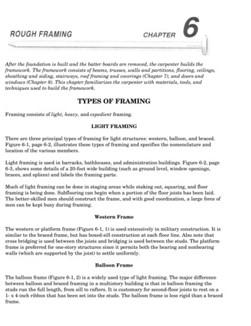
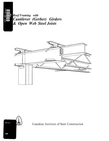
GFCAHFHConstruction Manual13.7.3.March 15, 2022Version 22.0Lean four remaining trusses against the gable end truss and secure them to prevent themfrom falling. Continue with installation of the remaining common trusses.INSTALLING PORCH TRUSSES1.Porch trusses are to be centered front-to-back on the porch framing. Locate the center ofthe porch framing and measure 12” in each direction to locate the center of the middletwo porch trusses. Continue 24” o.c. spacing in each direction as required.2.If not already completed, use 16d or 3¼” collated nails to secure 2x6s to the outsidefaces of the porch framing, keeping top and bottom edges flush.3.Nail pieces of scrap 2x4 to the top of the front porch framing spaced 2” back from thefront face to serve as blocking for the porch gable truss bottom chord.4.Make certain house wrap has been attached to the gable porch truss sheathing.5.Install the first porch truss on the truss layout mark. If one end of the porch trusses linesup with the house trusses, align the gable truss tail with the house truss tails by sightingalong the house trusses, or by using a straight 2x4 as a straight edge. If the porch roofdoes not have a surface common with the house roof, center the trusses side-to-side onthe porch framing.6.The remaining porch trusses are installed at the 24” layout marks and the gable porchtruss is set in place with the OSB sheathing flush with the outside face of the front porchframing. Secure the trusses with 6” timber screws through the porch framing into thetruss bottom chord.7.On houses with a porch at the gable end and with no truss against the house gable truss,a 2x4 must be nailed against the house’s gable truss, aligned with the line marked inSection 7.1.2.2.9, to support the edge of the porch roof sheathing.7.4.SHEATHING ROOF7.4.1. Cutting Full-Width Row OSB Roof Sheathing1.Refer to Figure 7-1 and Figure 7-2, below, which show examples of the roofsheathing layout for a 36’ and 30’ long roof, respectively. Note that each odd rowhas a 34” piece at the zero end, and each even row has a 58” piece on the zero end.Also, note that the bottom row is not full-width. The size of these bottom rowpieces will be determined in Section 7.4.2.2.Determine the non-zero end pattern, and the number of full and half-sheets. Using alarge marker or crayon, write the number and size of the end pieces required on theeave side of each corner of the house. The zero end will always require two each ofthe 34” and 58” pieces; the non-zero end will require two each of 62” and 38”7-7
GFCAHFHConstruction ManualMarch 15, 2022Version 22.0pieces. Also, write the number of full and half-sized pieces near the middle of thehouse where the sheets will be staged for lifting onto the roof.3.Cut four full sheets into 34”/62” pieces, and four more sheets into 38”/58” pieces.Label each piece with the size, using a red crayon.Figure 7-1. OSB Layout for 36’ Roof.Figure 7-2. OSB Layout for 30’ Roof.4.Place two 34” and two 58” pieces on each eave side of the house at the zero end, andtwo each of the 38” and 62” pieces on each eave side of the non-zero end. There aretypically 4 rows of sheeting on each side of the house, or 8 rows total. As shown inFigure 7-1, Figure 7-2, and Table 7-1, the 62” and 38” pieces are used on the nonzero end, but not necessarily in the same row as its corresponding cutoff.7-8
GFCAHFHConstruction ManualMarch 15, 2022Version 22.0Table 7-1. OSB Roof Sheathing Cut List Worksheet.Odd RowsEven RowsTotals for 4 FullWidth RowsTotal# of Non# of Non- Total # TotalZero FullZero FullRoof"4s" Zero"4s" Zero of Full # ofEnd SheetsEnd SheetsReq'd EndReq'd End Sheets 13858406232444344162584138328*Total Roof length Plan House length 2 feet7-9
GFCAHFHConstruction ManualMarch 15, 2022Version 22.07-10
GFCAHFHConstruction ManualMarch 15, 2022Version 22.05.Depending on the length of the house, a 4’ piece may also be needed in the middle ofthe row to reduce scrap and to maintain the stagger of the joints between sheets. Inthe 36’ example in Figure 7-1, a 4’ piece is required in each row. Figure 7-2 shows a4’ piece in even rows only. Referring to “Total # of 4s” in Table 7-1, determinethe number of 4’ pieces required. Cut full-width sheets in half to obtain the requirednumber, label with the size, and place half of them on each eave side of the housenear the middle.6.Referring to “Total # of Full Sheets” in Table 7-1, determine the number of fullsheets required. Place half of this number on each eave side of the house near themiddle.7.4.2. Planning OSB Roof Sheathing1.Roof sheathing is installed with a 1¼” overhang past the truss tails. At the peak, a2” opening is required for adequate attic ventilation. Any non-full-width row mustbe located at the bottom of the roof so the sub-fascia can provide adequate support.The following describes how to determine the number of rows of full-width (FW)sheets, the width of the bottom row, and the location of the chalk line to mark thebottom of the first FW row.2.Determine the number of rows of sheathing required by measuring the length (in feetand inches) of a truss top chord. Subtract the nearest lesser multiple of four from thefeet portion. Divide the multiple subtracted above by four; the result is the numberof FW rows. Subtract 2” from the remainder; the result is the location of the loweredge of the first FW row, measured up along the top edge of the truss tail. Then add1¼” to this number to get the width of the bottom row (see Example in Table 7-2).3.Use Table 7-1 to determine the number and sizes of sheets required for theappropriate length even row, and, for each side of the house, cut that number to thewidth calculated in Step 2.4.Measure up from the tail and mark the location of the chalk line (bottom of first FWrow) on each gable truss. Snap a chalk line from these marks across all the trusses.This line is the guide for the installation of the bottom edge of the first full-widthrow of OSB sheathing.Table 7-2. Example Roof Sheathing Calculations.18'-7¾"- (16'-0")Length of truss top chordSubtract nearest lesser multiple of 4; 16 4 4 FW rows 2'-7 ¾"Remainder- 2” 2’-5¾” 1¼”Subtract 2” – Ventilation gap at peakBottom of 1st full-width row, chalk line location (29¾”) 2'-7”Add 1¼” - amount sheet overhangs eave sub-fasciaWidth of bottom row (31”)7-11
GFCAHFHConstruction ManualMarch 15, 2022Version 22.07.4.3. Installing OSB Roof Sheathing1.For the first row, install a full-width 8’ long piece of OSB with the bottom edgealigned with the chalk line and one end centered on the second truss from the zeroend. With 8d nails, nail the bottom corner of the sheet at the second truss, thencheck the alignment of the bottom edge with the chalk line, center the other end ofthe sheet on its truss, and nail that bottom corner. At the top of the sheet, align thecorners with the centers of their trusses and nail. Measure from the edge of thesecond truss and mark on the upper edge of the sheet every 24”. Adjust each truss toits mark and nail.2.Repeat for each subsequent sheet, nailing the top of the sheet only. Align one topcorner with the adjacent sheet, leaving a ⅛” gap between sheet ends, and thediagonally opposite corner with the chalk line at the bottom. Nail the top corneradjacent to the previously installed sheet. Center the other top corner on its truss,recheck the alignment of the bottom with the chalk line, and nail the top corner.Measure the 24” truss spacing from a nailed truss that is not at a joint betweensheets. Nail into each truss along the top of the sheet with 8d nails. DO NOT nailthe bottom of the sheet at this time, since the tails will need to be straightened andspaced correctly before nailing. The sheet is secure so there is no need to nail anymore than this at this time.3.Before nailing the OSB at the gable end truss, be sure the gable truss is straight. Atthe wall top plate, measure between the gable truss and the adjacent common truss,and maintain that spacing between the gable truss and adjacent common truss foreach sheet of OSB installed. As a check, have the ground person sight along thegable truss, since the adjacent truss may not be straight.NOTE: The distance between the zero end gable truss and the firstcommon truss is 21¾”. The distance between the last commontruss and the non-zero gable end truss is more than 24” and willdepend on the actual house length.4.Before proceeding with the installation of additional sheathing rows, use 16d duplexnails (one nail per truss) to fasten a row of 2x4s along the entire length of the firstrow, 6” up from the bottom edge of the first sheets, to serve as a stop for tools,material, and personnel.5.Place H-clips on the OSB between each truss and start the second course (row) usingthe OSB piece cut earlier to stagger the OSB joints.6.Finish nailing the sheets using 2⅜” collated nails on every truss – seven nails on theedges and five in the field intervals. Check under the sheathing to make sure thenails hit the trusses.7.Before nailing the OSB at the gable edges, sight along the gable sub-fascia andstraighten as required, then nail the OSB edge into the sub-fascia using theprescribed pattern.7-12
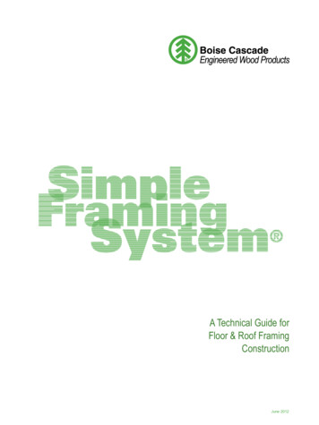
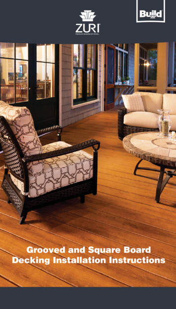
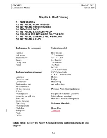
GFCAHFHConstruction Manual8.7.5.March 15, 2022Version 22.0If the OSB extends beyond the gable end sub-fascia, trim the edge flush to, or up to¼” short of, the outside face of the sub-fascia. Locate and mark the sub-fascia faceon the OSB and snap a chalk line. Cut using a circular saw set to ½” depth.INSTALLING EAVE SUB-FASCIA1.On the eave side of the house, position a long 2x6 sub-fascia, crown up, tight to theunderside of the sheathing. Extend one end flush to the outside face of the gable endsub-fascia, making sure the other end is centered on a truss tail. Cut to length asrequired. Nail the 2x6 to the ends of each truss with two 16d nails. Repeat at the otherend of the eave side and then fill in between them until the eave is finished.2.From the ground, sight along the eave sub-fascia and straighten the sub-fascia asrequired for appearance. Take extra time to do this. A straight piece of fascia will lookbetter against the gutter, while crooked or wavy sub-fascia will stand out.3.Once the sub-fascia is straight and true, nail the OSB to the eave sub-fascia using 8dnails on 8” intervals.7.6.BUILDING AND INSTALLING SCUTTLE BOX7.6.1.Building Scuttle Box1. Typically, the scuttle box is pre-built and delivered to the site prior to the day it is tobe installed. However, if it has not been built, use the following instructions to buildone. See Figure 7-3 for a picture of the finished scuttle box and Figure 7-4 andFigure 7-5 for schematic drawings.Figure 7-3. Scuttle Box.7-13
GFCAHFHConstruction ManualMarch 15, 2022Version 22.02. Cut four pieces of OSB: two sides, each 32” wide by 19¾” high and two ends, each25½” wide by 19¾” high.3. On the smooth face of the OSB end pieces, draw a line 16½” down from the top edge.Find the centers of the two 25½” edges and draw a line on the rough face betweenthem. Then draw two parallel lines on either side of the centerline 11¼” from it tolocate the inside edge of the 2x2s.4. On the smooth face of the side pieces, locate the center of the two 32” edges, anddraw parallel lines 14” to each side of that centerline. These lines will be used tolocate the inside edge of the end piece at assembly.5. At the bottom (non-factory) 25½” edge of each end piece, cut a notch 1⅝” wide by3⅜” high in the two corners. This leaves a tab 22¼” wide at the bottom that will fitwith a ¼” clearance between the truss bottom chords.Figure 7-4. Scuttle Box Cut Diagram.6. Cut two 2x4s 22½” long and two 2x4s 16½” long. Mark a centerline on the longerpair at 11¼” from each end.7. Rip each 16½” piece into two 2x2s (1½” square).8. On each OSB end piece, attach one of the 2x4s to the smooth face at the 16½” lineand with the centerlines aligned using a pair of 1⅝” screws at each end and a pair inthe middle. Check that the 2x4 extends below the OSB bottom edge, and that the 2x4ends are slightly beyond the edge of each notch.7-14
GFCAHFHConstruction ManualMarch 15, 2022Version 22.09. On the rough side of each end piece, attach a 2x2 even with the top of the 2x4 (flushwith the top of the OSB) and aligned with the vertical line drawn earlier. Attach with1⅝” screws, one at each end and one in the middle.Figure 7-5. Scuttle Box Assembly.10. Assemble the scuttle hole by setting the factory edges of the two sides and two endson a level surface to ensure that the top edges of the box will be flush with each other.11. With all smooth sides facing inward, align the end piece 2x2s with the vertical lineson the sides, and screw the sides to the 2x2’s using 1⅝” screws, three in each joint.Keep the box square as the connections are being made.7-15
GFCAHFHConstruction ManualMarch 15, 2022Version 22.012. Check that the box is square, place the square shipping corners tightly in twodiagonally opposite corners atop the 2x4, and screw in place.7.6.2. Installing Scuttle Box1. Before installing the house or garage scuttle box, confirm its location with theConstruction Supervisor.2. Lift the box (side-wise) into the attic and place it between the trusses in the locationspecified in the House Plan. Slide the assembled box along the trusses to optimizeease of access and clearance above.3. When the scuttle box is located in a bedroom, line up one end of the scuttle box withthe wall surface above the swinging door, so the wall rock above the door can extendup into that end of the scuttle box.4. When the scuttle box is located in a closet or pantry (typically at the end of stairs)keep the edge of scuttle box nearest the swinging door 4" from the wall surface abovethe door to leave a little room for the wall mounted light fixture that goes above thedoor in the closet or pantry so it doesn't interfere with attic access.5. Position the bottom of the scuttle box 2x4s flush with the bottom of the trusses andscrew the bottoms of the side pieces to the truss cords with 1⅝” screws, four on eachside. Using 16d nails, nail through the OSB and truss chords into the ends of thescuttle box’s 2x4x22½” cross-pieces.6. Remove the square shipping corners and give them to the Construction Supervisor.7.6.3. Assembling Scuttle Box Cover1. If the scuttle box cover has NOT been pre-assembled, assemble the cover using thefollowing steps.NOTE: The scuttle box cover is constructed in two pieces to aid in inserting theinsulation into the scuttle box2. Locate the piece of ¾” OSB pre-cut earlier to 25”x27½” for the cover. If not found,cut a new piece.3. Cut two pieces of poly about 48”x48”.4. Cut 25”x27½” pieces of 1” and/or 2” foamboard totaling 8” of thickness.5. Center the OSB on one of the poly pieces and place a 4”-thick stack of foamboard onthe OSB. Wrap the poly tightly up and over the foamboard and tape all poly edgestight to the foamboard with air sealing tape.7-16
GFCAHFHConstruction ManualMarch 15, 2022Version 22.06. Stack two pieces of 25”x27½”x5½” (11” total thickness) fiberglass insulation on thecenter of the second piece of poly. Without compressing the fiberglass, wrap andtape the poly edges tight to the insulation with air sealing tape.7.7.INSTALLING LATERALS AND X-BRACING7.7.1. Installing Lateral Truss Bracing1.After trusses have been installed, nail two to three rows of long 2x4 lateral bracingacross the tops of the bottom chords of the trusses with two 16d nails at each trussheld to a 24” spacing for ceiling sheet rock installation. Lateral bracing can bespaced a maximum of 10’ apart.2.Check the location of the scuttle hole before installing the bracing. The bracing orlocation of the scuttle may need to be adjusted to prevent the creation of p
7.2 INSTALLING ROOF TRUSSES 7.3 INSTALLING PORCH TRUSSES 7.4 SHEATHING ROOF 7.5 INSTALLING EAVE SUB-FASCIA 7.6 BUILDING AND INSTALLING SCUTTLE BOX 7.7 INSTALLING LATERALS AND X-BRACING . NOTE: Each gable requires a right and a left hand "ladder"; be sure to assemble each "ladder" with the inside 2x6 arranged in the correct orientation.