Transcription
ELISE MOSSAutodesk Certified InstructorAutodesk Revit 2018Architecture Basics From the Ground UpSDCP U B L I C AT I O N SBetter Textbooks. Lower Prices.www.SDCpublications.com
Visit the following websites to learn more about this book:Powered by TCPDF (www.tcpdf.org)
Mass ElementsLesson 2Mass ElementsMass Elements are used to give you a conceptual idea of the space and shape of abuilding without having to take the time to put in a lot of detail. It allows you to createalternative designs quickly and easily and get approval before you put in a lot of effort.Massing ToolsShow Mass by View Settings controls the visibility of massentities.Creates a solid shape.Controls the visibility of mass objects.Inserts a mass group into the active project.Model by Face:Converts a face into a Roof, Curtain Wall System, Wall, or Floor.When creating a conceptual mass to be used in a project, follow these steps:1.2.3.4.5.Create a sketch of the desired shape(s).Create levels to control the height of the shapes.Create reference planes to control the width and depth of the shapes.Draw a sketch of the profile of the shape.Use the Massing tools to create the shape.Masses can be used to create a component that will be used in a project, such as acolumn, casework, or lighting fixture, or they can be used to create a conceptual building.2-1
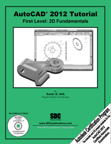
Revit Architecture BasicsExercise 2-1ShapesDrawing Name:Estimated Time:shapes.rfa5 minutesThis exercise reinforces the following skills: Creating the basic shapes using massing toolsCreate an extrudeModify the extrude heightCreate a revolveCreate a sweepCreate a blendModify a blend1.There are severalsketches in thefile.Each set ofsketches will beused to create aspecific type ofmass form.2.The most basic mass form is an extrude. Thismass form requires a single closed polygonalsketch.The sketch should have no gaps or selfintersecting lines.Select the rectangle so it highlights.3.When the sketch is selected, you will see gripsactivated at the vertices.2-2
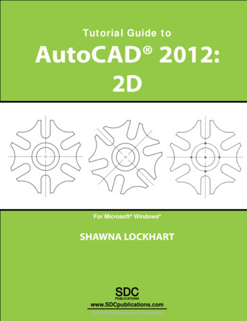
Mass Elements4.Select Create Form Solid Form to create the extrude.You won’t see the Create Form tool on the ribbon unless a sketchis selected.5.A preview of the extrude is displayed.You can use the triad on the top of theextrude to extend the shape in any of thethree directions.There are two dimensions:The bottom dimension controls the heightof the extrude.The top dimension controls the distancefrom top face of the extrude and the nextlevel.6.Activate the East Elevation.You can see how thedimensions are indicatingthe relative distancesbetween the top face andthe upper level, the bottomface, and another sketch.7.Change the 30′-0″ dimension to 45′-0″.To change the dimension, left click on the30' 0" dimension text.Press Enter.2-3
Revit Architecture Basics8.Note how the otherrelative dimensionsupdate.Left Click to exitdefining the mass.If you press Enter, youwill create a secondmass.9.Switch to a 3D view.10.Select the Front/North face of theblock.To select the face, place the mouseover the face and press the tab keyuntil the entire face highlights.This activates the triad and alsodisplays the temporary dimensions.You will see two temporarydimensions. One dimensionindicates the distance of the face tothe opposite face (the length of theblock). One dimension indicates thedistance of the face to the closestwork plane.11.Change the 88′ 0″ dimension to 90′-0″.Left click in the window to release theselection and complete the change.If you press Enter, you will create asecond mass.2-4
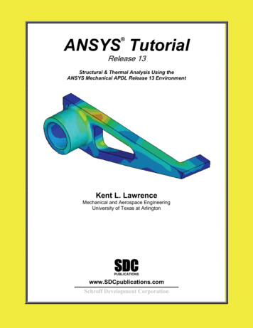
Mass Elements12.Use the View Cube to reorientthe view so you can clearly seethe next sketch.This sketch will be used tocreate a Revolve.A Revolve requires a closedpolygonal shape PLUS areference line which can beused as the axis of revolution.13.Hold down the CONTROL key and select the Axis Line(this is a reference line) and the sketch.Note that a reference line automatically defines fourreference planes. These reference planes can be used toplace sketches.14.15.Select Create Form Solid Form.A Revolve will be created.Our next mass form will be a SWEEP.A sweep requires two sketches. One sketch must be a closed polygonal shape. Thissketch is called the profile. The second sketch can be open or closed and is calledthe path. The profile travels along the path to create the sweep.2-5
Revit Architecture Basics16.Hold down the CONTROL key and select thesmall circle and the sketch that looks like aquestion mark.The two sketches will highlight.17.18.Select Create Form Solid Form.The sweep will be created.The most common error when creating a sweep is to make the profile too big for thepath. If the profile self-intersects as it travels along the path, you will get an errormessage. Try making the profile smaller to create a successful sweep.19.Our final shape will be a BLEND or LOFT.A blend is created using two or more openor closed sketches. Each sketch must beplaced on a different reference plane orlevel.Hold down the CONTROL key and selectthe three arcs.20.Select Create Form Solid Form.2-6
Mass Elements21.A blend shape is created.Close without saving.Challenge Task:Can you create the four basic shapes from scratch?Create an extrude, revolve, sweep and blend using New Conceptual Mass from theApplications menu.Steps to make an Extrude:1.2.3.4.5.Set your active plane using the Set Work Plane tool.Create a single polygonal sketch with no gaps or self-intersecting lines.Select the sketch.Create Form Solid Form.Green Check to finish the mass.Steps to make a Revolve:1.2.3.4.Set your active plane using the Set Work Plane tool.Switch to a 3D view.Draw a reference line to be used as the axis of revolution.Pick one of the planes defined by the reference line as the active plane to placeyour sketch.2-7
Revit Architecture Basics5. Create a single polygonal sketch – no gaps, overlapping or self-intersecting lines– for the revolve shape.6. Hold down the CONTROL key and select BOTH the sketch and reference line. Ifthe reference line is not selected, you will get an extrude.7. Create Form Solid Form.8. Green Check to finish the mass.Steps to make a Sweep:1. Activate Level 1 floor plan view. You need to select one reference plane for theprofile and one reference plane for the path. The reference planes must beperpendicular to each other. Set Level 1 for the path’s reference plane.2. Draw a path on Level 1. The path can be a closed or open sketch.3. Create a reference plane to use for the profile. Draw a reference plane on Level 1– name it profile plane. Make this the active plane for the profile sketch.4. Switch to a 3D view. Create a single polygonal sketch – no gaps, overlapping orself-intersecting lines. The profile sketch should be close to the path or intersect itso it can follow the path easily. If it is too far away from the path, it will notsweep properly or you will get an error.5. Hold down the CONTROL key and select BOTH the path and the profile. If onlyone object is selected, you will get an extrude.6. Create Form Solid Form.7. Green Check to finish the mass.Steps to make a Blend:1. Blends require two or more sketches. Each sketch should be on a parallelreference plane. You can add levels or reference planes for each sketch. If youwant your blend to be vertical, use levels. If you want your blend to be horizontal,use reference planes.a. To add levels, switch to an elevation view and select the Level tool.b. To add reference planes, switch to a floor plan view and select theReference Plane tool. Name the reference planes to make them easy toselect.2. Set the active reference plane using the Option Bar or the Set Reference Planetool.3. Create a single polygonal sketch – no gaps, overlapping or self-intersecting lines.4. Select at least one more reference plane to create a second sketch. Make this theactive plane.5. Create a single polygonal sketch – no gaps, overlapping or self-intersecting lines.6. Hold down the CONTROL key and select all the sketches created. If only oneobject is selected, you will get an extrude.7. Create Form Solid Form.8. Green Check to finish the mass.2-8
Mass ElementsExercise 2-2Create a Conceptual ModelDrawing Name:Estimated Time:default.rte [m default.rte]5 minutesThis exercise reinforces the following skills: Switching Elevation ViewsSetting Project UnitsAdd a LevelThis tutorial uses metric or Imperial units. Metric units will be designated in brackets.Revit uses a level to define another floor or story in a building.1.Select the default template on the Recent Fileswindow.This template was added to the Recent Files inExercise 1-8.If you do not have the default template file availableon the Recent Files window, press New.2.Under the Template file, selectBrowse.3.Locate the Imperial Templates folderunder ProgramData/Autodesk/RVT 2018.Locate the Metric Templates folderunder ProgramData/Autodesk/RVT2018.2-9
Revit Architecture Basics4.Notice the types of templates available in each of thesefolders.The number of templates available was determinedwhen the software was installed. You can add moretemplates by modifying the installation using theControl Panel or download additional templates fromAutodesk’s content library.Select the default.rte [DefaultMetric.rte]template.5.Brackets indicate metric, which can beselected as an alternative.Press OK.If you accidentally picked Metric when you wanted Imperial or vice versa, you canchange the units at any time.To change Project Units, go to the Manage Ribbon.Select Settings Project Units.Left click the Length button, then selectthe desired units from the drop-down list.6.Double click East under Elevations.This activates the East view orientation.7.8.Select the Architecture ribbon.Select the Level tool under Datum. (This adds a floor elevation.)2-10
Mass Elements9.Move your mouse to set an elevation of 12′ [3650 mm].Pick to start the elevation line.10.In the Options bar, enable Make Plan View.The Options bar can be located below the ribbon or at the bottom of the screen.If the Options bar is located below the ribbon and youwould prefer it on the bottom of the screen, right click and select Dock at Bottom.If the Options bar is located at the bottom of the screenand you would prefer it to be below the ribbon, right click on the Options bar andselect Dock at Top.Make Plan View should be enabled if you want Revit to automatically create a floorplan view of this level. If you forget to check this box, you can create the floor planview later using the View Ribbon.Double click on the blue elevation symbol to automatically switch to thefloor plan view for that elevation.11.Pick to place the end point to position the level indicatorabove the other indicators.12. Basically, you place a new level by picking two points at the desired height.Right click and select Cancel to exit the Level command.Revit is always looking for references even among annotations; you will notice thatyour level tags snap and lock together so when you move one to the right or left, allthose in line with it will follow.2-11
Revit Architecture BasicsThe jogged line allows the user to create a jog if desired.If you need to adjust the position of the tag, just click on the line; 3 blue grips willappear. These can be clicked and dragged as needed. You can also right click on alevel tag and select ‘Hide annotation in view’ and the tag and level line willdisappear in that view only.Hide Annotation in View is only enabled if an object is selected first.13. Save the file as a project as ex2-2.rvt.Exercise 2-3Adding an In-Place MassDrawing Name:Estimated Time:ex2-2.rvt10 minutesThis exercise reinforces the following skills: 1.2.3.4.Switching Elevation ViewsAdd MassOpen or continue working in the file ex2-2.rvt.Activate the Level 1 view.Select the Massing & Site ribbon.Select the In-Place Mass tool.Revit uses three different family categories. System families are families which aredefined inside the project, such as floors, walls, and ceilings. Loadable families areexternal files which can be loaded into the project, such as doors, windows, andfurniture. The third family category is in-place masses, which are families createdon-the-fly.2-12
Mass Elements5.Masses, by default, are invisible. However, inorder to create and edit masses you need to seewhat you are doing. Revit brings up a dialog tolet you know that the software is switching thevisibility of masses to ON, so you can work.Press Close.If you don’t want to be bugged by this dialog, enable the Don’t show me thismessage again option.6.Enter Mass 1 in the Name field.Press OK.7.Next, we create the boundary sketch to define our mass. This is the footprint for theconceptual building.Select the Line tool located under the Drawpanel.8.Enable Chain in the Options bar.This allows you to draw lines without always having to pick the start point.If you hold down the SHIFT key while you draw, this puts you in orthogonal mode.9.Create the shape shown.The left figure shows the units in Imperial units (feet and inches).The right figure shows the units in millimeters.You can draw using listening dimensions or enter the dimension values as you draw.Revit doesn’t have a CLOSE command for the LINE tool unlike AutoCAD, so you dohave to draw that last line.10. Exit out of drawing mode by right clicking and selecting Cancel twice, selectingESC on the keyboard or by selecting the Modify button on the ribbon.2-13
Revit Architecture Basics11.Switch to a 3D view.Activate the View ribbon and select 3D View.You can also switch to a 3D view from the Quick Access toolbar byselecting the house icon.12. Window around the entire sketch so it is highlighted.13.Select Form Create Form Solid Form.You must select the sketch to create the form.If the sketch has any gaps, overlapping lines, or self-intersectinglines, you will get an error. Exit the command and inspect thesketch to make sure it is a cleanly closed polygon.14.15.An extrusion distance is displayed.This can be edited, if desired.Select the gr
Revit uses a level to define another floor or story in a building. 1. Select the default template on the Recent Files window. This template was added to the Recent Files in Exercise 1-8. If you do not have the default template file available on the Recent Files window, press New. 2.