Transcription
Autodesk Revit 2018 MEPFundamentals SDCP U B L I C AT I O N SBetter Textbooks. Lower Prices.www.SDCpublications.com
Visit the following websites to learn more about this book:Powered by TCPDF (www.tcpdf.org)
ChapterBasic Sketching and ModifyToolsBasic sketching, selecting, and modifying tools are the foundation of working withall types of elements in the Autodesk Revit software, including componentssuch as air terminals, plumbing fixtures, and electrical devices. Using these toolswith drawing aids helps you to place and modify elements to create accuratebuilding models.Learning Objectives in this Chapter Ease the placement of elements by incorporating drawing aids, such as alignment lines,temporary dimensions, permanent dimensions, and snaps. Place Reference Planes as temporary guide lines. Insert components such as mechanical equipment, plumbing fixtures, and electrical devices. Use techniques to select and filter groups of elements. Modify elements using a contextual tab, Properties, temporary dimensions, and controls. Move, copy, rotate, and mirror elements and create array copies in linear and radial patterns. 2017, ASCENT - Center for Technical Knowledge 2–1
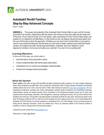
Autodesk Revit 2018 MEP: Fundamentals2.1 Using General SketchingToolsWhen you start a command, the contextual tab on the ribbon,Options Bar, and Properties palette enable you to set up featuresfor each new element you are placing in the project. As you startmodeling, several features called drawing aids display, as shownin Figure 2–1. They help you to create designs quickly andaccurately.Contextual tabOptions BarDrawing aidsProperties paletteFigure 2–1 When you model ducts, pipes, cable trays, or conduits orplace elements such as air terminals, lighting fixtures orplumbing fixtures, you first need to: Drawing Aids2–2Select a type from the Type Selector.Set information in the Options Bar.Check the Contextual tab for other options.As soon as you start sketching or placing elements, severaldrawing aids display, including: Alignment lines Temporary dimensions Snaps Connectors 2017, ASCENT - Center for Technical Knowledge
Basic Sketching and Modify ToolsThese aids are available with most drawing and manymodification commands, as shown in Figure 2–2.Alignment LinesSnapsTemporary DimensionsFigure 2–2Alignment lines display as soon as you move the cursor overnearby elements. They help keep lines horizontal, vertical, or ata specified angle. They also line up with the implied intersectionsof walls and other elements. Hold Shift to force the alignments to be orthogonal (90degree angles only).Temporary dimensions display to help place elements at thecorrect length, angle and location. You can type in the dimension and then move the cursor untilyou see the dimension you want, or you can place theelement and then modify the dimension as required. The length and angle increments shown vary depending onhow far in or out the view is zoomed. For Imperial measurements (feet and inches), the softwareuses a default of feet. For example, when you type 4 andpress Enter , it assumes 4’-0”. For a distance such as 4’-6”,you can type any of the following: 4’-6”, 4’6, 4-6, or 4 6 (thenumbers separated by a space). To indicate distances lessthan one foot, type the inch mark (”) after the distance, orenter 0, a space, and then the distance. 2017, ASCENT - Center for Technical Knowledge 2–3
Autodesk Revit 2018 MEP: FundamentalsHint: Temporary Dimensions and Permanent DimensionsTemporary dimensions disappear as soon as you finish addingelements. If you want to make them permanent, select thecontrol shown in Figure 2–3.Figure 2–3Snaps are key points that help you reference existing elementsto exact points when drawing, as shown in Figure 2–4.Figure 2–4 When you move the cursor over an element, the snapsymbol displays. Each snap location type displays with adifferent symbolConnectors (MEP only) work similar to snaps, but have moreintelligence about the size, system, and flow of items (e.g., ducts,pipes, and electrical connections). For example, connectorsautomatically add fittings to ducts, such as the elbow, transition,and tee shown in Figure 2–5.Fittings controlled by connectorsFigure 2–52–4 2017, ASCENT - Center for Technical Knowledge
Basic Sketching and Modify ToolsHint: Snap Settings and OverridesIn the Manage tab Settings panel, click(Snaps) to openthe Snaps dialog box, which is shown in Figure 2–6. The Snapsdialog box enables you to set which snap points are active, andset the dimension increments displayed for temporarydimensions (both linear and angular).Figure 2–6 Keyboard shortcuts for each snap can be used to overridethe automatic snapping. Temporary overrides only affect asingle pick, but can be very helpful when there are snapsnearby other than the one you want to use. 2017, ASCENT - Center for Technical Knowledge 2–5
Autodesk Revit 2018 MEP: FundamentalsUsingDimensions asDrawing AidsDimensions are a critical part of construction documents, butthey can also help you create elements in your model. There area variety of dimension types available to you, but the most usefulis the Aligned Dimension with the Individual References option.How To: Add Aligned Dimensions to IndividualReferences1. In the Quick Access Toolbar or the Modify tab Measurepanel, click(Aligned Dimension). Alternatively, type DI.2. Select the elements in order, as shown in Figure 2–7.3. To position the dimension string, click a point at a locationwhere it is not touching anything else.Figure 2–7 When you are using dimensions in a model, you can set astring of dimensions so that they are equal. Doing thisupdates the model elements, such as the location ofsprinklers shown in Figure 2–8.BeforeAfterFigure 2–82–6 2017, ASCENT - Center for Technical Knowledge
Basic Sketching and Modify ToolsHint: Measuring ToolsWhen modifying a model, it is useful to know the distancebetween elements. This can be done with temporarydimensions, or more frequently, by using the measuring toolsfound in the Quick Access Toolbar or on the Modify tab Measure panel, as shown in Figure 2–9.Figure 2–9 (Measure Between Two References): Select twoelements and the measurement displays. (Measure Along An Element): Select the edge of alinear element and the total length displays. 2017, ASCENT - Center for Technical Knowledge 2–7
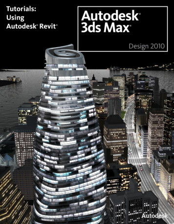
Autodesk Revit 2018 MEP: FundamentalsReferencePlanesAs you develop designs in the Autodesk Revit software, thereare times when you need lines to help you define certainlocations. You can draw reference planes (which display asdashed green lines) and snap to them whenever you need to lineup elements. For the example shown in Figure 2–10, the lightingfixtures in the reflected ceiling plan are placed using referenceplanes. To insert a reference plane, in the Architecture, Structure, orSystems tab Work Plane panel, clicktype RP.(Ref Plane) orFigure 2–10 Reference planes display in associated views because theyare infinite planes, and not just lines. You can name Reference planes by clicking on Click toname and typing in the text box, as shown in Figure 2–11.Figure 2–112–8 If you sketch a reference pane in Sketch Mode (used withfloors and similar elements), it does not display once thesketch is finished. Reference planes can have different line styles if they havebeen defined in the project. In Properties, select a style fromthe Subcategory list. 2017, ASCENT - Center for Technical Knowledge
Basic Sketching and Modify Tools2.2 Inserting ComponentsComponents (also known as families) are full 3D elements thatcan be placed at appropriate locations and heights, and whichinteract with the building elements around them. For example, alighting fixture can be designed to be hosted by a face (such as awall or ceiling), or to stand alone by itself, as shown inFigure 2–12. The Autodesk Revit software includes botharchitectural components (such as the lamp and wall sconces inFigure 2–12) and MEP components (such as the downlightfixtures) that include l-basedfamilyComponents arelocated in family fileswith the extension .RFA.For example, acomponent familynamed Wall Sconce.rfacan contain severaltypes and sizes.Figure 2–12Most components are inserted using specific tools, including:Exact steps for insertingspecific components arecovered later in thisstudent guide.Air terminalMechanical EquipmentPlumbing FixtureElectrical EquipmentDevices (Data, FireAlarm, Switches, etc.)Lighting FixturesSprinkler 2017, ASCENT - Center for Technical Knowledge 2–9
Autodesk Revit 2018 MEP: Fundamentals Take time to get to know the components that come with theAutodesk Revit software. Their most critical content are theconnectors, as you see in for a piece of mechanicalequipment in Figure 2–13.Figure 2–13 Connectors often contain options to create systems and drawducts and pipes when you right-click on them.How To: Insert Components1. Start the appropriate command.2. In the Type Selector, select the type/size you want to use, asshown in Figure 2–14.Figure 2–142–10 2017, ASCENT - Center for Technical Knowledge
Basic Sketching and Modify Tools3. In the command-specific contextual tab Tag panel, click(Tag on Placement) to toggle this option on or off.4. Proceed as follows, based on the type of component used:If thecomponent is.Then.Not hostedSet the Level and Offset in Properties, as shown inFigure 2–15.Wall hostedSet the Elevation in Properties, as shown inFigure 2–16.Face hostedSelect the appropriate method in the contextual tab Placement panel, as shown in Figure 2–17. Vertical Faces include walls and columns. Faces include ceilings, beams, and roofs. Work Planes can be set to levels, faces, and namedreference planes.Figure 2–15Figure 2–16Figure 2–175. Place the component in the model. A fast way to add components that match those already inyour project is to select one, right-click on it, and selectCreate Similar, as shown in Figure 2–18. This starts theappropriate command with the same type selected.Figure 2–18 2017, ASCENT - Center for Technical Knowledge 2–11
Autodesk Revit 2018 MEP: FundamentalsHint: Work PlanesA Work Plane is the surface you sketch on or extrude from. In aplan view, the Work Plane is automatically parallel to the level.In an elevation or 3D view, you must specify the Work Planebefore you start sketchingHow To: Select a Work Plane1. Start a command that requires a work plane or, in theArchitecture tab Work Plane panel, click(Set).2. In the Work Plane dialog box, select one of the followingoptions: Name: Select an existing level, grid, or named referenceplane (as shown in Figure 2–19) and then click OK.Figure 2–19 Pick a plane: Click OK and select a plane in the view,such as a wall face. Ensure the entire plane ishighlighted before you select it. Pick a line and use the work plane it was sketchedin: Click OK and select a model line, such as a roomseparation line.If you are in a view in which the sketch cannot be created, theGo To View dialog box opens. Select one of the views and clickOpen View.2–12 2017, ASCENT - Center for Technical Knowledge
Basic Sketching and Modify ToolsLoadingComponentsYou can load additional families into a project. In the contextualtab Mode panel, click(Load Family) and then navigate tothe appropriate location for your company. The Autodesk Revitlibrary has MEP-based components available in the followingfolders: Cable Tray, Conduit, Duct, Electrical, Fire Protection,Lighting, Mechanical, Pipe, and Plumbing.How To: Load a Family1. In the related contextual tab Mode panel or Insert tab Loadfrom Library panel, click(Load Family).2. In the Load Family dialog box, locate the folder that containsthe family or families you want to load, as shown inFigure 2–20.Figure 2–203. Select the family or families you want to load. You can hold Ctrl to select multiple families.4. Click Open. 2017, ASCENT - Center for Technical Knowledge 2–13
Autodesk Revit 2018 MEP: FundamentalsHint: Matching PropertiesYou can select an existing wall and use it to assign the wall typeand instance properties to other walls by using the Match Typecommand. This command also works with all elements thathave types.1. In the Modify tab Clipboard panel, click(Match Type) ortype MA. The cursor changes to an arrow with a cleanpaintbrush.2. Select the source element that you want all of the others tomatch. The paintbrush changes to look as if it has beendipped in black paint as shown in Figure 2–21.Figure 2–213. To select more than one element, in the Modify Match Typetab Multiple panel, click(Select Multiple). You can thenuse windows, crossings, Ctrl , and Shift to create aselection set of elements to change.4. Select the elements that you want to change. For multipleselections, clickselection.2–14(Finish) to apply the type to the Click in an empty space in the project to empty the brush sothat you can repeat the command with a different element. Elements to be matched must be of the same type (e.g., allwalls, all doors, etc.). 2017, ASCENT - Center for Technical Knowledge
Basic Sketching and Modify ToolsPractice 2aInsert ComponentsPractice Objectives Load and Insert components. Use drawing aids. Add and name a reference plan. Select a work plane.Estimated time forcompletion: 10 minutesMechanicalIn this practice you will insert a variety of MEP fixtures, includingair terminals, plumbing fixtures and lighting fixtures, as shown inFigure 2–22. You will use various drawing aids to help you placethe fixtures appropriately.PlumbingElectricalFigure 2–22Task 1 - Insert air terminals.1. In the practice files Basics folder, openSimple-Building-Start.rvt.2. In the Project Browser, expand the Mechanical HVAC Floor Plans node. The 1 - Mech view is highlighted, and youare in a Mechanical floor plan.3. In the Systems tab HVAC panel, click(Air Terminal).4. In Properties, note that the default selection is a
As you develop designs in the Autodesk Revit software, there are times when you need lines to help you define certain locations. You can draw reference planes (which display as dashed green lines) and snap to them whenever you need to line up elements. For the example shown in Figure2–10, the lighting fixtures in the reflected ceiling plan are placed using reference planes. To insert a .