Transcription
AutoCAD 2012 Tutorial First Level: 2D FundamentalsbyRandy H. ShihOregon Institute of TechnologyMULTIMEDIA CD INSIDE:INCLUDED:A videopresentation ofSDCPUBLICATIONSwww.SDCpublications.comSchroff Development Corporationselected tutorialsand exercises
Visit the following websites to learn more about this book:
AutoCAD 2012 Tutorial: 2D FundamentalsChapter 1AutoCAD Fundamentals Create and Save AutoCAD drawing files Use the AutoCAD visual referencecommands Draw, using the LINE and CIRCLEcommands Use the ERASE command Define Positions using the Basic Entrymethods Use the AutoCAD Pan Realtime option1-1
1-2AutoCAD 2012 Tutorial: 2D FundamentalsAutoCAD Certified Associate Examination Objectives CoverageThis table shows the pages on which the objectives of the Certified Associate Examination are covered inChapter 1.Section 1: Controlling the Display in DrawingsPrecision.1-4Zoom Extent.1-5Drawing LIMITS .1-5Status Bar .1-10GRID Display .1-10, 1-11PAN Realtime .1-20Certified Associate Reference GuideSection 2: Creating Basic DrawingsFormat .1-5Units Setup .1-5LINE command.1-8Coordinates .1-8Interactive Input method .1-9SNAP Option .1-10World space .1-15User coordinate system .1-15World coordinate system .1-15UCS icon Display .1-16TTR, circle .1-16Relative Coordinate .1-17Coordinate systems .1-17Cartesian coordinate system .1-17Absolute coordinates.1-17, 1-18Positions, defining.1-18LINE, Close option .1-19CIRCLE command.1-23TTT, circle .1-23ARC command . 1-33Section 3: Manipulating ObjectsERASE command .1-13Selection window.1-14
AutoCAD Fundamentals1-3IntroductionLearning to use a CAD system is similar to learning a new language. It is necessary tobegin with the basic alphabet and learn how to use it correctly and effectively throughpractice. This will require learning some new concepts and skills as well as learning adifferent vocabulary. Today, the majority of the Mechanical CAD systems are capable ofcreating three-dimensional solid models. Nonetheless, all CAD systems create designsusing basic geometric entities and many of the constructions used in technical designs arebased upon two-dimensional planar geometry. The method and number of operations thatare required to accomplish the basic planar constructions are different from one system toanother.In order to become effective and efficient in using a CAD system, we must learn to creategeometric entities quickly and accurately. In learning to use a CAD system, lines andcircles are the first two, and perhaps the most important two, geometric entities that oneshould master the skills of creating and modifying. Straight lines and circles are used inalmost all technical designs. In examining the different types of planar geometric entities,the importance of lines and circles becomes obvious. Triangles and polygons are planarfigures bounded by straight lines. Ellipses and splines can be constructed by connectingarcs with different radii. As one gains some experience in creating lines and circles,similar procedures can be applied to create other geometric entities. In this chapter, thedifferent ways of creating lines and circles in AutoCAD 2012 are examined.Starting Up AutoCAD 20121. Select the AutoCAD 2012 option on the Program menu or select theAutoCAD 2012 icon on the Desktop. Once the program is loaded into memory, the AutoCAD 2012 drawingscreen will appear on the screen.
1-4AutoCAD 2012 Tutorial: 2D Fundamentals Note that AutoCAD automatically assigns generic name, Drawing X, as newdrawings are created. In our example, AutoCAD opened the graphics window usingthe default system units and assigned the drawing name Drawing1.2. If necessary, click on the down-arrow in the Quick Access bar and selectShow Menu to display the AutoCAD Menu Bar. The Menu Bar providesaccess to all AutoCAD commands.AutoCAD Menu Bar
AutoCAD Fundamentals1-5Drawing Units Setup Every object we construct in a CAD system is measured in units. We shoulddetermine the system of units within the CAD system before creating the firstgeometric entities.1. In the Menu Bar select:[Format] [Units] The AutoCAD Menu Bar contains multiple pull-downmenus, where all of the AutoCAD commands can beaccessed. Note that many of the menu items listed inthe pull-down menus can also be accessed through theQuick Access toolbar and/or Ribbon panels.2. Click on the Length Typeoption to display the differenttypes of length unitsavailable. Confirm the LengthType is set to Decimal.3. On your own, examine the other settings that areavailable.4. In the Drawing Units dialog box, set the Length Type to Decimal. This willset the measurement to the default English units, inches.
1-6AutoCAD 2012 Tutorial: 2D Fundamentals5. Set the Precision to two digits afterthe decimal point as shown in theabove figure.6. Pick OK to exit the Drawing Unitsdialog box.Drawing Area Setup Next, we will set up the Drawing Limits by entering a command in thecommand prompt area. Setting the Drawing Limits controls the extents of thedisplay of the grid. It also serves as a visual reference that marks the workingarea. It can also be used to prevent construction outside the grid limits and as aplot option that defines an area to be plotted/printed. Note that this setting doesnot limit the region for geometry construction.1. In the Menu Bar select:[Format] [Drawing Limits]2. In the command prompt area, the message “Reset ModelSpace Limits: Specify lower left corner or [On/Off] 0.00,0.00 :” is displayed. Press the ENTER key once toaccept the default coordinates 0.00,0.00 .3. In the command prompt area, the message “Specify upper right corner 12.00,9.00 :” is displayed. Press the ENTER key again to accept the defaultcoordinates 12.00,9.00 .
AutoCAD Fundamentals1-74. On your own, move the graphic cursor near the upper-right comer inside thedrawing area and note that the drawing area is unchanged. (The DrawingLimits command is used to set the drawing area, but the display will not beadjusted until a display command is used.)5. Inside the Menu Bar areaselect:[View] [Zoom] [All] The Zoom Allcommand will adjust thedisplay so that all objectsin the drawing aredisplayed to be as largeas possible. If no objectsare constructed, theDrawing Limits are usedto adjust the currentviewport.6. Move the graphic cursor near the upper-right comer inside the drawing area andnote that the display area is updated.7. Hit the function key [F7] once to turn off the display of the Grid lines. Note that function key [F7] is a quick key which can be used to quickly toggleon/off the grid display.
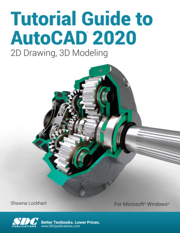
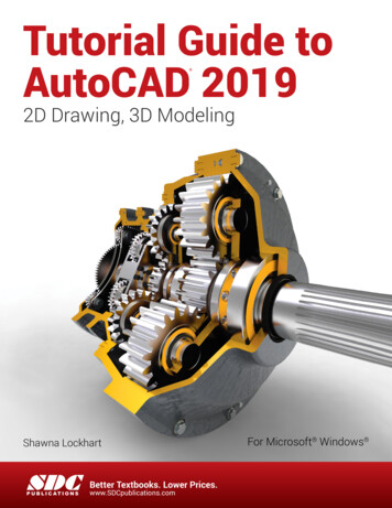
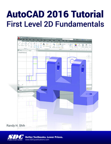
AutoCAD 2012 Tutorial: 2D Fundamentals1-8Drawing lines with the LINE command1. Move the graphics cursor to the first icon inthe Draw panel. This icon is the Line icon.Note that a brief description of the Linecommand appears next to the cursor.2. Select the icon by clicking once with the leftmouse-button, which will activate the Linecommand.3. In the command prompt area, near the bottom of the AutoCAD drawingscreen, the message “ line Specify first point:” is displayed. AutoCADexpects us to identify the starting location of a straight line. Move the graphicscursor inside the graphics window and watch the display of the coordinates ofthe graphics cursor at the bottom of the AutoCAD drawing screen. The threenumbers represent the location of the cursor in the X, Y, and Z directions. Wecan treat the graphics window as if it was a piece of paper and we are usingthe graphics cursor as if it were a pencil with which to draw.Coordinates of the graphicscursor.53214 We will create a freehand sketch of a fivepoint star using the Line command. Do notbe overly concerned with the actual size orthe accuracy of your freehand sketch. Thisexercise is to give you a feel for theAutoCAD 2012 user interface.
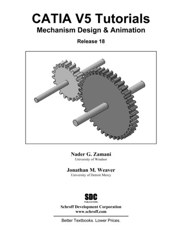
AutoCAD Fundamentals1-94. We will start at a location about one-thirdfrom the bottom of the graphics window.Left-click once to position the startingpoint of our first line. This will be point 1of our sketch. Next move the cursorupward and toward the right side of point1. Notice the rubber-band line that followsthe graphics cursor in the graphicswindow. Left-click again (point 2) and wehave created the first line of our sketch.5. Move the cursor to the left of point 2 andcreate a horizontal line about the samelength as the first line on the screen.536. Repeat the above steps and completethe freehand sketch by adding threemore lines (from point 3 to point 4,point 4 to point 5, and then connect topoint 5 back to point 1).2147. Notice that the Line command remains activated even afterwe connected the last segment of the line to the starting point(point 1) of our sketch. Inside the graphics window, clickonce with the right-mouse-button and a popup menuappears on the screen.8. Select Enter with the left-mouse-button to end the Linecommand. (This is equivalent to hitting the [ENTER] key onthe keyboard.)9. Move the cursor near point 2 and point 3, and estimate thelength of the horizontal line by watching the displayedcoordinates for each point.
1-10AutoCAD 2012 Tutorial: 2D FundamentalsVisual referenceThe method we just used to create the freehand sketch is known as the interactivemethod, where we use the cursor to specify locations on the screen. This method isperhaps the fastest way to specify locations on the screen. However, it is rather difficultto try to create a line of a specific length by watching the displayed coordinates. It wouldbe helpful to know what one inch or one meter looks like on the screen while we arecreating entities. AutoCAD 2012 provides us with many tools to aid the construction ofour designs. For example, the GRID and SNAP MODE options can be used to get avisual reference as to the size of objects and learn to restrict the movement of the cursorto a set increment on the screen.The GRID and SNAP MODE options can be turned ON or OFF through the Status Bar.The Status Bar area is located at the bottom left of the AutoCAD drawing screen, next tothe cursor coordinates.Option ButtonsThe second button in the Status Bar is the SNAP MODE option and the third button is theGRID DISPLAY option. Note that the buttons in the Status Bar area serve two functions:(1) the status of the specific option, and (2) as toggle switches that can be used to turnthese special options ON and OFF. When the corresponding button is highlighted, thespecific option is turned ON. Using the buttons is a quick and easy way to make changesto these drawing aid options. Another aspect of the buttons in the Status Bar is theseoptions can be switched on and off in the middle of another command.
AutoCAD Fundamentals1-11GRID ON1. Left-click the GRID button in the Status Bar to turn ON the GRID DISPLAYoption. (Notice in the command prompt area, the message “ Grid on ” isalso displayed.)2. Move the cursor inside the graphics window, and estimate the distance inbetween the grid lines by watching the coordinates display at the bottom ofthe screen. The GRID option creates a pattern of lines that extends over an area on the screen.Using the grid is similar to placing a sheet of grid paper under a drawing. The gridhelps you align objects and visualize the distance between them. The grid is notdisplayed in the plotted drawing. The default grid spacing, which means the distancein between two lines on the screen, is 0.5 inches. We can see that the sketchedhorizontal line in the sketch is about 5 inches long.
1-12AutoCAD 2012 Tutorial: 2D FundamentalsSNAP MODE ON1. Left-click the SNAP MODE button in the Status Bar to turn ON the SNAPoption.2. Move the cursor inside the graphics window, and move the cursor diagonallyon the screen. Observe the movement of the cursor and watch the coordinatesdisplay at the bottom of the screen. The SNAP option controls an invisible rectangular grid that restricts cursormovement to specified intervals. When SNAP mode is on, the screen cursor andall input coordinates are snapped to the nearest point on the grid. The default snapinterval is 0.5 inches, and aligned to the grid points on the screen.3. Click on the Line icon in the Draw toolbar. In thecommand prompt area, the message “ line Specifyfirst point:” is displayed.4. On your own, create another sketch of the five-point star with the GRID andSNAP opti
AutoCAD 2012 provides us with many tools to aid the construction of our designs. For example, the GRID and SNAP MODE options can be used to get a visual reference as to the size of objects and learn to restrict the movement of the cursor to a set increment on the screen. The GRID and SNAP MODE options can be turned ON or OFF through the Status Bar. The Status Bar area is located at the .