Transcription
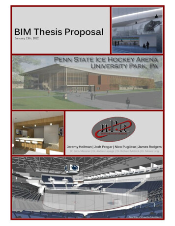
BIM Thesis ProposalJanuary 13th, 2012Jeremy Heilman Josh Progar Nico Pugilese James RodgersDr, John Messner Dr, Andres Lepage Dr. Richard Mistrick Dr. Moses Ling
HPR Integrated DesignBIM THESIS PROPOSALJeremy Heilman Josh Progar Nico Pugilese James Rodgers[Executive Summary]The Penn State Ice Arena is the focus of the Integrated Project Delivery/ BuildingInformation Modeling (IPD/BIM) Senior Thesis. This report will serve as a proposal for HPRIntegrated Design’s alternative design strategies to achieve more efficient building systems withineach discipline. The goals of these strategies are to deliver a facility that will have the highestquality for the budget allotted, reduce building’s energy usage and cost, create a fast trackedschedule, and develop a LEED Gold certified hockey arena.HPR Integrated Design has chosen to focus on three areas of study during the spring 2012semester. They are as follows: Raising of the Event Level – Design Focus 1 Main Arena Roof System Design – Design Focus 2 Façade Redesign – Design Focus 3Raising of the Event Level:The current design shows a floor to floor height between the event level and mainconcourse level of 20 foot 9 inches. With this height level, there is 10 foot plenum space. The drivingforce behind raising the event level is to reduce the amount of bedrock needed to be excavatedfrom the site. In doing so, the plenum space will be reduced. HPR believes that by raising the eventlevel approximately three feet, excavation costs will be reduced and plenum space that isotherwise wasted will be optimized. Savings from the reduction of excavation will then bereallocated to the main arena roof system design to give the Penn State University a facility ofgreater value for the same construction cost.Main Arena Roof System Design:When HPR received the drawings for the Penn State Ice Arena, the main arena roofsystem’s design had not been completed. HPR’s designers will coordinate and design a roof for themain arena that is iconic and that will support the overhead lighting and duct systems.Façade Redesign:With the design of the new roof system, the façade will have to be redesigned in order tocoordinate in the efforts to design an iconic facility. As the façade is redesigned, materials will beselected and configured to maximize daylighting, reduce energy loads, and reduce constructionand energy costs.HPR Integrated Design Penn State Ice Arena University Park, PAi
HPR Integrated DesignBIM THESIS PROPOSALJeremy Heilman Josh Progar Nico Pugilese James RodgersThe raising of the event level and the main arena roof systems are very closely connected.As the volume of the main arena is increased by a new roof profile it is then reduced by moving theevent level up. On a financial side, money saved in excavation by raising the event level can thenbe reallocated to the more prominent arena roof structural and MEP systems. This will provide theUniversity with a higher valued product for a competitive cost to the original design.This proposal will serve as a guide for the Architectural Engineering faculty to monitor andassess the progress that HPR Integrated Design will achieve in the spring 2012 semester. Buildinginformation modeling with integrated project delivery design processes will be used heavily incoordination of the design team throughout the semester to implement these design alternatives.All modeling will be done using BIM based software such as the Autodesk Revit platforms andNavisworks. Individual discipline design will be conducted in appropriate analytical programs thatcan be exported or imported into these interfaces. HPR is constantly aware of the collaborativenature of the design process and will monitor the lead and lag of each task.HPR Integrated Design Penn State Ice Arena University Park, PAii
HPR Integrated DesignBIM THESIS PROPOSALJeremy Heilman Josh Progar Nico Pugilese James Rodgers[Table of Contents]Penn State Ice Arena Overview . 1Construction Management . 2Existing Architecture. 2Existing Façade & Building Enclosure . 4Existing Mechanical System . 4Existing Lighting Systems. 7Existing Electrical Systems . 7Existing Structural System . 8Design Focus: Event Level Raising . 12Problem Statement . 12Construction Approach. 15Mechanical Approach . 16Lighting/Electrical Approach . 17Structural Approach . 18BIM & Interdisciplinary Approach. 21Event Level Raising Conclusion . 22Design Focus: Main Arena Roof System Design . 23Problem Statement . 23Construction Approach. 24Mechanical Approach . 25Lighting/Electrical Approach . 26Structural Approach . 27BIM & Interdisciplinary Approach. 30Main Arena Roof System Design Conclusion. 31Design Focus: Façade Redesign. 32Problem Statement . 32Construction Approach. 32Mechanical Approach . 33Lighting/Electrical Approach . 34HPR Integrated Design Penn State Ice Arena University Park, PAiii
HPR Integrated DesignBIM THESIS PROPOSALJeremy Heilman Josh Progar Nico Pugilese James RodgersStructural Approach . 36BIM & Interdisciplinary Approach. 37Façade Redesign Conclusion . 38Appendix A: Deliverables, Software, & Codes . 39HPR Integrated Design Team Deliverables . 39Construction Deliverables . 39Mechanical Deliverables . 40Lighting/Electrical Deliverables . 40Structural Deliverables . 41Appendix B: Measures for Success . 42Event Level Relocation . 42Main Arena Roof System Design. 42Façade Redesign . 43Appendix C: Proposed Schedule & Timetable . 44Proposed Schedule . 44Detailed Schedule – Event Level Raising. 45Detailed Schedule – Main Arena Roof System Design . 46Detailed Schedule – Façade Redesign . 47Appendix D: BIM Execution Planning . 48BIM Goals . 48BIM Uses Worksheet. 49Appendix E: BIM File Management . 50File Naming Structure . 50BIM Model Strorage Location . 50Electronic Communication Procedures – Filing Sharing . 51Appendix F: Index of Figures & Tables . 52Figures . 52Tables. 53HPR Integrated Design Penn State Ice Arena University Park, PAiv
HPR Integrated DesignBIM THESIS PROPOSALJeremy Heilman Josh Progar Nico Pugilese James RodgersAppendix G: MAE Thesis Requirements . 54Construction MAE . 54Mechanical MAE . 54Structural MAE. 54HPR Integrated Design Penn State Ice Arena University Park, PAv
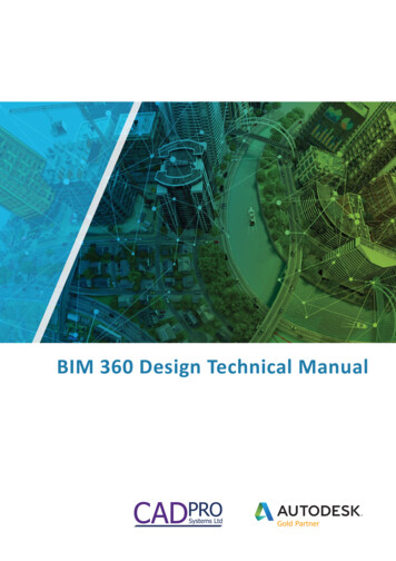
HPR Integrated DesignBIM THESIS PROPOSALJeremy Heilman Josh Progar Nico Pugilese James Rodgers[Penn State Ice Arena Overview]The Penn State Ice Hockey Arena will be home to the newly developed Penn State NCAADivision 1 men’s and women’s hockey teams. The new facility will be located on University Drive onthe Penn State University Campus, between Holuba Hall and Shields Building (the location can beseen as the blue box in Figure 1). The facility is a 3-story, 220,000 square-foot arena containing 2regulation sized ice sheets. A few features that are important to the facility are its proximity to theother major campus sports facility (the Bryce Jordan Center and Beaver Stadium) and its view ofMt. Nittany from the Mt. Nittany room. There is a footprint constraint for this site; a main campusutility artery runs parallel with the west side of the site depicted in Figure 1 as a yellow line.Figure 1: Site and SurroundingsEach floor is occupiable, with the event level hosting the ice sheets, office spaces, lockerrooms, and training rooms. The main concourse level, where the main and student entrances arelocated, has restaurant services, concession stands, and the Mt. Nittany room. There are 14 suitesHPR Integrated Design Penn State Ice Arena University Park, PA1
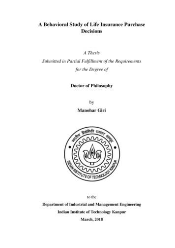
HPR Integrated DesignBIM THESIS PROPOSALJeremy Heilman Josh Progar Nico Pugilese James Rodgersand 2 lodge boxes for the Penn State President and donors. The main competition arena will beable to hold 6,000 spectators, while the auxiliary arena will hold 300 spectators.Construction ManagementIn September 2010, a private donor provided Penn State with a gift and the opportunity tobuild a Penn State Ice Hockey Arena for its Division 1 men’s and women’s hockey teams. Thisdonation was made in the amount of 88 million, with an additional private donor donating 1million. Of the 89 million donation, 73 million has been budgeted for the development andconstruction of this project. Mortenson Construction has been selected as the project managementfirm. The teams will officially become a Division 1 program in the 2012 to 2013 hockey season, butthe facility will not be completed until the 2013 to 2014 season. Preconstruction will begin inJanuary 2012, with construction slated to begin in March 2012. Construction is expected to becompleted by September 2013 in time for the first scheduled puck drop on October 11, 2013. Theproject is being delivered as a Design-Build project with a LEED Gold Certification.Existing ArchitectureThe existing architectural style of the Penn State Ice uses many of the common buildingmaterials found on campus. It is mostly brick with a large glass eastern façade. The currentdesign calls for a slightly pitched metal deck roof. Many features of the building are gearedtowards enhancing the audiences experiences while at a Penn State hockey game, largevomitories, panoramic views, and optimized viewing angles, among many others.Both sheets of ice are on the event level (shown in Figure 2) along with buildingadministration offices, visitor locker rooms, team locker rooms and team support areas. The mainarena ice sheet plays host to the men and women varsity hockey program. The second sheet, theauxiliary rink, has been branded the “workhorse” of the facility and will service local patrons andother leagues. The entrance for the auxiliary rink side of the facility is located on the southeasternside of the building. The electrical, mechanical, and ice plant rooms are all located on the westerncorner of the event level.HPR Integrated Design Penn State Ice Arena University Park, PA2
HPR Integrated DesignBIM THESIS PROPOSALJeremy Heilman Josh Progar Nico Pugilese James RodgersNZamboni EntranceLoading DockAuxiliary Rink EntranceImage Courtesy of Crawford Architects, LLCFigure 2: Event Level Floor PlanThe main concourse level, shown in Figure 3, will be the level in which the majority ofpatrons will occupy during a game. It holds all of the main vomitories to enter the arena bowl aswell as restrooms and concessions. The main building entrance is located on the northern cornerof the building; patrons of the building are greeted by a 2 story atrium which opens up to threeoptions for traveling around the building, the main concourse which wraps the main bowl, a grandstair case to the club level and a large vomitory into the arena bowl. The main student entrance islocated on the west façade.NStudent EntranceMain EntranceMt. Nittany RoomImage Courtesy of Crawford Architects, LLCFigure 3: Main Concourse Level Floor PlanHPR Integrated Design Penn State Ice Arena University Park, PA3
HPR Integrated DesignBIM THESIS PROPOSALJeremy Heilman Josh Progar Nico Pugilese James RodgersThe club level (Figure 4) is located on the top level. Located on this level are the club suites,club lounge, a dining space, and a kitchen to support the suites and the dining space.NImage Courtesy of Crawford Architects, LLCFigure 4: Club Level Floor PlanExisting Façade & Building EnclosureThe existing exterior façade architectural style of the ice arena is one that has graced thePenn State campus for many years. Large facades made of mostly brick with penetrations comingfrom the windows. One exception to this standard is northeast façade. In the preliminary designsthis façade is a large glass curtain wall spanning the entire width of the building and wrapping thecorners.Existing Mechanical SystemThe current design for the Penn State Ice Arena uses the campus chilled water plant toprovide chilled water for space cooling and the campus steam plant to meet loads. The lowpressure steam from the pressure reducing valve (PRV) station puts the steam through a heatexchanger and the building ultimately uses hot water.The building is served by twelve air handling units (AHU 1-12) and two dehumidifying units(AHU 13, 14). The twelve air handling units can be divided in to three separate categories:1.Energy recovery and dehumidification2.Energy recovery3.EconomizerHPR Integrated Design Penn State Ice Arena University Park, PA4
HPR Integrated DesignBIM THESIS PROPOSALJeremy Heilman Josh Progar Nico Pugilese James RodgersGroup 1 (AHU 10-12) serves the main competition bowl and the auxiliary ice rink where it isimportant to control humidity. These areas are also served by the two dehumidification units.Group 2 (AHU 5, 7, 8, 9) serves both of the varsity looker rooms, the community looker rooms, andthe offices. The energy recovery is done with a heat pipe. Group 3 (AHU 1-4, 6) serves theconcourses, kitchen, restaurant, and weight room. The economizer is important in these areasbecause the occupancy is transient; if the amount of outdoor air can be controlled based on bothoutside temperature and occupancy there can be drastic energy savings. The remaining spacesare served by separate fan coil units.The air handling units are located on the roof above the concourse level. Supply ductsfrom the two units serving the main arena bowl are able to penetrate into the main arena while thatof the other units must go down through mechanical shafts. AHU 7, 8, 13, 14 are located on theconcourse level, not the age Courtesy of Crawford Architects, LLCFigure 5: Existing AHU Zoning for the Event LevelHPR Integrated Design Penn State Ice Arena University Park, PA5
HPR Integrated DesignBIM THESIS PROPOSALJeremy Heilman Josh Progar Nico Pugilese James RodgersAHU-3AHU-10AHU-12AHU-11AHU-2AHU-4Image Courtesy of Crawford Architects, LLCFigure 6: Existing AHU Zoning for the Concourse LevelAHU-3AHU-10AHU-11AHU-2AHU-1Image Courtesy of Crawford Architects, LLCFigure 7: Existing AHU Zoning for the Club LevelHPR Integrated Design Penn State Ice Arena University Park, PA6
HPR Integrated DesignBIM THESIS PROPOSALJeremy Heilman Josh Progar Nico Pugilese James RodgersExisting Lighting SystemsThe lighting systems for the Penn State Ice Arena are all served on a 277V distribution system.The main arena has 1000 watt metal halide indoor sports lighting fixtures with black out shutters.An array of linear fluorescent high bays luminaries light the community rink. Other areas, includingthe concourse, lockers, concessions, restrooms, and lounges, of the building do not have lightingspecified in the set of drawings provided at the beginning of the year. Site lighting is provided onboth the northwest and the southeast side of the buildings by a pole mounted Louis Poulson fixturethat is standard for Penn State. This fixture has a 100 watt metal halide lamp and is mounted at 12’above finished grade. Lighting in the parking lot is provided by Lumark Tribute Series, whichcontains a 250 watt high pressure sodium lamp mounted at 25’; this also is the Penn Statestandard.Lighting controls for the building are not specified in the set of drawings provided at thebeginning of the year.Existing Electrical SystemsThe normal building electrical service is provided by the Penn State campus loop and israted at 12,470 Volts. Two pad mounted transformers reduce the voltage to the building operationalvoltage of 480Y/277 Volts. Each transformer is rated at 2,500 KVA and serves one side of thebuilding’s double-ended substation (main-tie-main). The substation consists of two mainswitchboards rated at 3000 Amps each. One of the main switchboards has service disconnectsthat feed the critical and equipment automatic transfer switches. Beyond the main switchboard liedistribution panels for both equipment and lighting rated at 480Y/277 Volts. An emergencyautomatic transfer switch is served from the equipment distribution panel. Step down transformersare also used throughout the building to service the receptacle load.Emergency building electrical services are provided by the Penn State emergency campusloop and are rated at 4,180 Volts. A separate transformer is used to step down the primary voltageto 480Y/277 Volt. This transformer serves the emergency automatic transfer switch, rated at 200Amps. The emergency distribution system has the same basic hierarchy as the normal system,with a distribution panel serving the load and step down transformers.HPR Integrated Design Penn State Ice Arena University Park, PA7
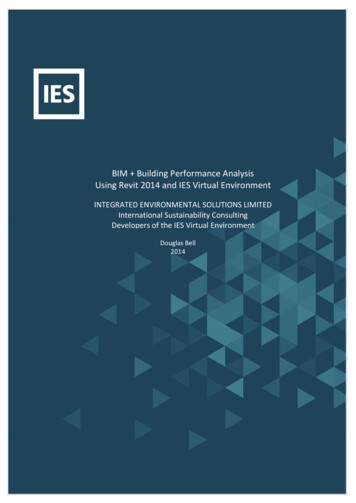
BIM THESIS PROPOSALHPR Integrated DesignJeremy Heilman Josh Progar Nico Pugilese James RodgersExisting Structural SystemThe foundation system for the Penn State Ice Arena consists of a combination of micropileswith pile caps, grade beams, isolated footings, and strip footings. Micropiles with pile caps areused west of the main competition arena where the elevation of top of bedrock may vary. Isolatedfootings are used on all interior columns around the main competition bowl while strip footings areutilized around the exterior walls of the arena. Figure 8 shows the current foundation system withthe area around the main competition bowl that is anticipated to be micropiles with pile caps.Image Courtesy of Crawford Architects, LLCFigure 8: Existing Foundation SystemsThe event level flooring systems are slabs on grade, all at the same elevation. In thenorthwest corner of the arena, between the event level and the main concourse level, is adepressed floor slab that is utilized for hiding mechanical equipment. This depressed slab consistsof a 7 ½” normal weight concrete composite slab with W18 beams and W24 girders framingmembers.All concrete used on the Penn State Ice Arena project will be 4,000 psi. Steel reinforcementboth in the foundation system and throughout all other concrete walls will be 60 ksi.HPR Integrated Design Penn State Ice Arena University Park, PA8
HPR Integrated DesignBIM THESIS PROPOSALJeremy Heilman Josh Progar Nico Pugilese James RodgersThe event level is on the same elevation and covers the entire footprint of the arena. Thereis a 20’-9” floor to floor height from the event level to the main concourse level. A 12” concretefoundation wall frames the full 20’-9” dimension from the northeast corner to the west corner of thefacility. The east side of the building footprint has no foundation wall. Between the west corner andthe south corner of the building, the foundation wall tapers down with the grade change.Around the main competition sheet of ice, the main concourse level and club level consistof the typical one way, 4 ½” normal weight concrete composite slab on 3”, 18 gauge VLI compositedeck. The total slab thickness is therefore 7 ½”. The composite slab is supported with framingmembers that consist of W18 beams and W24 girders. The beams and girders frame by W18exterior columns and W24 interior columns at the intersection of grid lines. Typical bays on theselevels range from 37’-2” by 28’-0” (largest bay) to 28’-8” by 28’-0” (smallest bay).Special structural framing that is unique to the ice arena consists of the main competitionbowl being made up of a precast “tub” which contains precast seating treads and risers supportedon W30 sloped beams and intermediate HSS steel members. Additionally, both the competitionand practice sheets of ice are installed over top of a 6” slab on grade that is insulated to avoid slabupheaval due to freeze/thaw cycles throughout the year.Long span, simply supported steel trusses span 196’-0” from column line Y3 to Y9 runningnorth-south with bracing trusses spanning 240’-5” from column line X6 to X13 running east-west.These bracing trusses are supported by the perpendicular main long span trusses. The top andbottom chords for all trusses are W14’s with double angles utilized as the diagonals.Figure 9 shows a simplified high roof framing plan. The high roof sits approximately 5’-11”above the flat lower roof covering the entire main sheet of ice and the surrounding lower seatingbowl of the arena. The simply supported truss, shown in Figure 10, is sloped slightly to a high pointin the middle. These trusses are 10’-0” deep at the exterior supports and 13’-9” at midspan. Thebracing trusses, shown in Figure 11, are not sloped and are a constant 10’-0” deep. Bottom of thehigh steel is 50’-0” clear from the top of the ice, ideal for an ice hockey arena. Intermediate framingbetween these trusses support 3”, 18 gauge roof deck.HPR Integrated Design Penn State Ice Arena University Park, PA9
HPR Integrated DesignBIM THESIS PROPOSALJeremy Heilman Josh Progar Nico Pugilese James RodgersImage Courtesy of Crawford Architects, LLCFigure 9: High Roof Framing PlanImage Courtesy of Crawford Architects, LLCFigure 10: Simply Supported Existing Long Span TrussImage Courtesy of Crawford Architects, LLCFigure 11: Bracing TrussThe lower flat roof wraps around the long span high roof covering the main lobby andexterior main vomitories that circle the main seating bowl. The lower roof spans the 28’ wide northand south concourses around the competition arena with 24K8 bar joists. This low roof systemslopes up on the north side of the building to meet the high roof top of steel to create a grand entryat the northern main entrance of the facility. Additionally, the auxiliary rink roofing system consistsof sloped deep long span trusses that span the 110’ wide space.HPR Integrated Design Penn State Ice Arena University Park, PA10
HPR Integrated DesignBIM THESIS PROPOSALJeremy Heilman Josh Progar Nico Pugilese James RodgersThe lateral system for the arena consists of a combination of moment frames, bracedframes and shear walls. Shear walls are designed starting from the event level and terminate atthe main concourse level. The main concourse level has a small two bay braced frame runningalong column line D between column lines 12 – 13. This is the sole braced frame designed in thefacility and extends up another level to the event level.The majority of the lateral systems are designed as moment frames at the club level.Moment frames run the east-west direction above both the north an
The Penn State Ice Arena is the focus of the Integrated Project Delivery/ Building Information Modeling (IPD/BIM) Senior Thesis. This report will serve as a proposal for HPR . seen as the blue box in Figure 1). The faci