Transcription
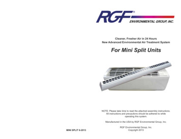
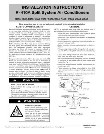
INSTALLATION INSTRUCTIONSR--410A Split System Air ConditionersN4A3, NXA4, N4A5, N4A6, NXA6 / R4A3, R4A4, R4A5 / WCA3, WCA4, WCA5These instructions must be read and understood completely before attempting installation.SAFETY CONSIDERATIONSGENERALImproper installation, adjustment, alteration, service, maintenance,or use can cause explosion, fire, electrical shock, or otherconditions which may cause death, personal injury, or propertydamage. Consult a qualified installer, service agency, or yourdistributor or branch for information or assistance. The qualifiedinstaller or agency must use factory--authorized kits or accessorieswhen modifying this product. Refer to the individual instructionspackaged with the kits or accessories when installing.Follow all safety codes. Wear safety glasses, protective clothing,and work gloves. Use quenching cloth for brazing operations.Have fire extinguisher available. Read these instructionsthoroughly and follow all warnings or cautions included inliterature and attached to the unit. Consult local building codes andcurrent editions of the National Electrical Code (NEC) NFPA 70.In Canada, refer to current editions of the Canadian electrical codeCSA 22.1.NOTE: In some cases noise in the living area has been traced togas pulsations from improper installation of equipment.1. Locate unit away from windows, patios, decks, etc. whereunit operation sound may disturb customer.2. Ensure that vapor and liquid tube diameters are appropriatefor unit capacity.3. Run refrigerant tubes as directly as possible by avoiding unnecessary turns and bends.4. Leave some slack between structure and unit to absorb vibration.5. When passing refrigerant tubes through the wall, seal opening with RTV or other pliable silicon--based caulk. (See Fig.1.)6. Avoid direct tubing contact with water pipes, duct work,floor joists, wall studs, floors, and walls.7. Do not suspend refrigerant tubing from joists and studs witha rigid wire or strap which comes in direct contact withtubing.(See Fig. 1.)8. Ensure that tubing insulation is pliable and completely surrounds vapor tube.9. When necessary, use hanger straps which are 1 in. (25.4mm) wide and conform to shape of tubing insulation. (SeeFig. 1.)10. Isolate hanger straps from insulation by using metal sleevesbent to conform to shape of insulation.Recognize safety information. This is the safety--alert symbol !!When you see this symbol on the unit and in instructions ormanuals, be alert to the potential for personal injury. Understandthese signal words; DANGER, WARNING, and CAUTION. Thesewords are used with the safety--alert symbol. DANGER identifiesthe most serious hazards which will result in severe personal injuryor death. WARNING signifies hazards which could result inpersonal injury or death. CAUTION is used to identify unsafepractices which would result in minor personal injury or productand property damage. NOTE is used to highlight suggestionswhich will result in enhanced installation, reliability, or operation.WARNING!NOTE: Avoid contact between tubing and structureOUTDOOR WALLINDOOR WALLCAULKLIQUID TUBEELECTRICAL SHOCK HAZARDFailure to follow this warning could result in personalinjury or death.Before installing, modifying, or servicing system, mainelectrical disconnect switch must be in the OFF position.There may be more than 1 disconnect switch. Lock out andtag switch with a suitable warning label.!INSULATIONTHROUGH THE WALLJOISTHANGER STRAP(AROUND VAPORTUBE ONLY)INSULATIONVAPOR TUBEWARNINGEXPLOSION HAZARDFailure to follow this warning couldresult in death, serious personal injury,and/or property damage.VAPOR TUBE1” (25.4 mm) MIN.Never use air or gases containingoxygen for leak testing or operatingrefrigerant compressors. Pressurizedmixtures of air or gases containingoxygen can lead to an explosion.SUSPENSIONLIQUID TUBEA94026Fig. 1 -- Piping InstallationCatalog No: 42101550100Manufacturer reserves the right to change, at any time, specifications and designs without notice and without obligations.Replaces: New
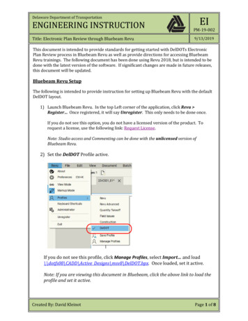
For proper unit operation, check refrigerant charge using charginginformation located on control box cover and/or in the CheckCharge section of this instruction.IMPORTANT: Maximum liquid--line size is 3/8--in. OD for allresidential applications including long line. Refer to ResidentialPiping and Longline Guideline for further information.IMPORTANT: Always install the factory--supplied liquid--linefilter drier. If replacing the filter drier, refer to Product Data Digestfor appropriate part number. Obtain replacement filter driers fromyour distributor or branch.INSTALLATIONNOTE: 18” (457.2 mm) clearance option described above isapproved for outdoor units with wire grille coil guard only.Units with louver panels require 24” (609.6 mm) between units.On rooftop applications, locate unit at least 6 in. (152.4 mm) aboveroof surface.Operating AmbientThe minimum outdoor operating ambient in cooling mode withoutaccessory is 55 F (12.78 C), and the maximum outdooroperating ambient in cooling mode is 125 F (51.67 C).Make Piping Connections!WARNING!IMPORTANT: Effective January 1, 2015, all split system airconditioners and heat pumps must be installed pursuant to theregional efficiency standards issued by the Department ofEnergy.PERSONAL INJURY AND ENVIRONMENTALHAZARDFailure to follow this warning could result in personal injury ordeath.CAUTIONFailure to follow this caution may result in personal injury.Relieve pressure and recover all refrigerant before systemrepair or final unit disposal. Use all service ports and open allflow--control devices, including solenoid valves.Sheet metal parts may have sharp edges or burrs. Use care andwear appropriate protective clothing and gloves whenhandling parts.Federal regulations require that you do not vent refrigerant tothe atmosphere. Recover during system repair or final unitdisposal.CUT HAZARDCheck Equipment and Job SiteUNIT DAMAGE HAZARDFailure to follow this caution may result in equipmentdamage or improper operation.Inspect EquipmentFile claim with shipping company prior to installation if shipmentis damaged or incomplete. Locate unit rating plate on unit cornerpanel. It contains information needed to properly install unit.Check rating plate to be sure unit matches job specifications.If ANY refrigerant tubing is buried, provide a 6--in (152.4mm). vertical rise at service valve. Refrigerant tubinglengths up to 36--in (914.4 mm). may be buried withoutfurther special consideration. Do not bury lines more than36--in. (914.4 mm).Install on a Solid, Level Mounting PadIf conditions or local codes require the unit be attached to pad, tiedown bolts should be used and fastened through knockoutsprovided in unit base pan. Refer to unit mounting pattern in Fig. 2to determine base pan size and knockout hole location.For hurricane tie downs, contact local distributor for details and PE(Professional Engineer) certification, if required by localauthorities.On rooftop applications, mount on level platform or frame. Placeunit above a load--bearing wall and isolate unit and tubing set fromstructure. Arrange supporting members to adequately support unitand minimize transmission of vibration to building. Consult localcodes governing rooftop applications.Roof mounted units exposed to winds may require wind baffles.Consult the Application Guideline and Service Manual -Residential Split System Air Conditioners and Heat Pumps forwind baffle construction.NOTE: Unit must be level to within 2 ( 3/8 in./ft ,. 9.5 mm/m)per compressor manufacturer specifications.Clearance RequirementsWhen installing, allow sufficient space for airflow clearance,wiring, refrigerant piping, and service. Allow 24 in. (609.6 mm)clearance to service end of unit and 48 in. (1219.2 mm) (aboveunit. For proper airflow, a 6--in. (152.4 mm) clearance on 1 side ofunit and 12--in. (304.8 mm) on all remaining sides must bemaintained. Maintain a distance of 24 in. (609.6 mm) betweenunits or 18 in. (457.2 mm) if no overhang within 12 ft. (3.66 m)Position so water, snow, or ice from roof or eaves cannot falldirectly on unit.CAUTION!UNPACK UNITMove to final location. Remove carton taking care not to damageunit.3/8--- in. (9.53 mm) Dia.Tiedown Knockouts inBasepan(2) PlacesView From TopTIEDOWN KNOCKOUT LOCATIONS in. (mm)UNIT BASE PANDimension in. (mm)ABC23 ---1/2 X 23 .8)(596.9 X 596.9)26 X 269–1/8 (231.8)4–7/16 (112.7)21–1/4 (539.8)(660.4 X 660.4)31–1/2 X 31–1/29–1/8 (231.8)6–9/16 (166.7) 24–11/16 (627.1)(800.1 X 800.1)35 X 359–1/8 (231.8)6–9/16 (166.7) 28–7/16 (722.3)(889 X 889)A05177Fig. 2 -- Tiedown Knockout LocationsOutdoor units may be connected to indoor section using accessorytubing package or field--supplied refrigerant grade tubing of correctsize and condition. Rated tubing diameters shown in Table 1 arerecommended up to 80 ft. (24.38 m). See Product Data foracceptable alternate vapor diameters and associated capacity losses.For tubing requirements beyond 80 ft. (24.38 m), substantialCatalog No: 42101550100Manufacturer reserves the right to change, at any time, specifications and designs without notice and without obligations.2Replaces: New
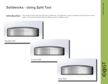
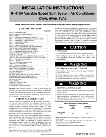
capacity and performance losses can occur. Following therecommendations in the Longline Guideline will reduce theselosses. Refer to Table 1 for field tubing diameters. Refer to Table 5for accessory requirements.There are no buried--line applications greater than 36--in. (914.4mm) allowed.If refrigerant tubes or indoor coil are exposed to atmosphere, theymust be evacuated to 500 microns to eliminate contamination andmoisture in the system.Install Liquid-- Line Filter Drier IndoorUNIT DAMAGE HAZARDFailure to follow this caution may result in equipmentdamage or improper operation.1. Installation of filter drier in liquid line is required.Outdoor Unit Connected to Factory Approved IndoorUnitOutdoor unit contains correct system refrigerant charge foroperation with factory approved AHRI rated indoor unit whenconnected by 15 ft. (4.57 m) of field--supplied or factory--accessorytubing, and factory supplied filter drier. Check refrigerant chargefor maximum efficiency.NOTE: Some units may require additional charge amounts for 15ft (4.57 m) line sets. Refer to the chart in the Check Charge sectionfor further instructions.CAUTION!2. Filter drier must be wrapped in a heat--sinking materialsuch as a wet cloth while brazing.Refer to Fig. 3 and install filter drier as follows:1. Braze 5--in. liquid tube to the indoor coil.2. Wrap filter drier with damp cloth.3. Braze filter drier to above 5--in. (127 mm) liquid tube.Flow arrow must point towards indoor coil.4. Connect and braze liquid refrigerant tube to the filter drier.Refrigerant Tubing Connection OutdoorConnect vapor and liquid tubes to fittings on vapor and liquidservice valves (see Table 1.) Use refrigerant grade tubingSweat Connection!CAUTIONA05178UNIT DAMAGE HAZARDFig. 3 -- Liquid Line Filter DrierFailure to follow this caution may result in equipmentdamage or improper operation.Evacuate Refrigerant Tubing and Indoor CoilTable 1 – Refrigerant Connections and Recommended Liquidand Vapor Tube Diameters (In.)UNIT SIZE18, 24303642, 4860LIQUIDConnection& Max. TubeDiameter3/83/83/83/83/8RATED 83/43/47/87/81 ---1/8* Units are rated with 25 ft. (7.6 m) of lineset. See Product Data sheet forperformance data when using different size and length linesets.Notes:1. Do not apply capillary tube or fixed orifice indoor coils to these units.2. For Tubing Set lengths between 80 and 200 ft. (24.38 and 60.96 m)horizontal or 35 ft. (10.7 m) vertical differential 250 ft. (76.2 m) TotalEquivalent Length), refer to the Residential Piping and Longline Guideline --- Air Conditioners and Heat Pumps using R---410A refrigerant.3. For alternate liquid line options on 18 ---42 size units, see Product Data orResidential Piping and Application GuidelineUNIT DAMAGE HAZARDFailure to follow this caution may result in equipmentdamage or improper operation.Never use the system compressor as a vacuum pump.Refrigerant tubes and indoor coil should be evacuated using therecommended deep vacuum method of 500 microns. The alternatetriple evacuation method may be used (see triple evacuationprocedure in service manual). Always break a vacuum with drynitrogen.Deep Vacuum MethodThe deep vacuum method requires a vacuum pump capable ofpulling a vacuum of 500 microns and a vacuum gage capable ofaccurately measuring this vacuum depth. The deep vacuum methodis the most positive way of assuring a system is free of air andliquid water. A tight dry system will hold a vacuum of 1000microns after approximately 7 minutes. See Fig. 4.MICRONSUse refrigeration grade tubing. Service valves are closed fromfactory and ready for brazing. After wrapping service valve with awet cloth, braze sweat connections using industry acceptedmethods and materials. Consult local code requirements.Refrigerant tubing and indoor coil are now ready for leak testing.This check should include all field and factory joints.CAUTION!Service valves must be wrapped in a heat--sinking materialsuch as a wet cloth while K INSYSTEMVACUUM TIGHTTOO WETTIGHTDRY SYSTEM01234MINUTES567A95424Fig. 4 -- Deep Vacuum GraphCatalog No: 42101550100Manufacturer reserves the right to change, at any time, specifications and designs without notice and without obligations.3Replaces: New
Final Tubing CheckIMPORTANT: Check to be certain factory tubing on both indoorand outdoor unit has not shifted during shipment. Ensure tubes arenot rubbing against each other or any sheet metal or wires. Payclose attention to feeder tubes, making sure wire ties on feedertubes are secure and tight.Installing with Indoor PistonOutdoor Unit Connected to Factory Approved Indoor UnitCheck piston size shipped with indoor unit to see if it matchesrequired indoor piston size. If it does not match, replace indoorpiston with correct piston size.When changing indoor piston, use a back up wrench. Handtighten hex nut, then tighten with wrench 1/2 turn. Do not exceed30 ft lbs. The indoor piston contains a Teflon ring (or seal) whichis used to seat against the inside of distributor body, and must beinstalled properly to ensure proper seating. See Fig.13/16” BRASS HEX NUTTEFLON SEALTEFLON RINGS3/4” BRASS HEX BODY“H” DISTRIBUTORPISTONPISTON RETAINERA10342Fig. 5 -- Indoor (Cooling) Piston!CAUTIONPRODUCT OPERATION HAZARDFailure to follow this caution may result in equipmentdamage or improper operation.If using a TXV in conjunction with a single--phasereciprocating compressor, a compressor start capacitor andrelay are required.Units with Cooling Mode TXVUnits installed with cooling mode TXV require charging by thesubcooling method.1. Operate unit a minimum of 15 minutes before checkingcharge.2. Measure liquid service valve pressure by attaching an accurate gage to service port.3. Measure liquid line temperature by attaching an accuratethermistor type or electronic thermometer to liquid line nearoutdoor coil.4. Refer to unit rating plate for required subcooling temperature.5. Refer to Table 2 -- Rating Plate (required) Subcooling Temperature. Find the point where required subcooling temperature intersects measured liquid service valve pressure.6. To obtain required subcooling temperature at a specific liquid line pressure, add refrigerant if liquid line temperatureis higher than indicated or reclaim refrigerant if temperatureUnits with Indoor PistonUnits installed with indoor pistons require charging by thesuperheat method.The following procedure is valid when indoor airflow is within 21 percent of its rated CFM.1. Operate unit a minimum of 15 minutes before checkingcharge.2. Measure suction pressure by attaching an accurate gage tosuction valve service port.3. Measure suction temperature by attaching an accurate thermistor type or electronic thermometer to suction line at service valve.4. Measure outdoor air dry bulb temperature with thermometer.5. Measure indoor air (entering indoor coil) wet--bulb temperature with a sling psychrometer.6. Refer to Table 3 -- Superheat Charging -- AC Only. Findoutdoor temperature and evaporator entering air wet--bulbtemperature. At this intersection, note superheat. Where adash (----) appears on the table, do not attempt to charge system under these conditions or refrigerant slugging may occur. Charge must be weighted in, adding or removing 0.6oz/ft of 3/8 liquid line above or below 15 feet (4.6m) respectively.7. Refer to Table 4 -- Required Suction--Line Temperature.Find superheat temperature (from #6 above) and suctionpressure. At this intersection, note suction line temperature.8. If unit has a higher suction line temperature than chartedtemperature, add refrigerant until charted temperature isreached.9. If unit has a lower suction line temperature than chartedtemperature, reclaim refrigerant until charted temperature isreached.10. When adding refrigerant, charge in liquid form into suctionservice port using a flow--restricting device.11. If outdoor air temperature or pressure at suction valvechanges, charge to new suction line temperature indicatedon chart.12. Optimum performance will be achieved when the operatingcharge produces 10 F suction superheat at suction servicevalve with 95 F (35 C) outdoor ambient and 80 F (27 C)dry bulb (67 F / 19 C) wet bulb) indoor temperature (DOE“A” test conditions) at rated airflow.is lower. Allow a tolerance of 3 F ( 1.7 C).Catalog No: 42101550100Manufacturer reserves the right to change, at any time, specifications and designs without notice and without obligations.4Replaces: New
Table 2 – Rating Plate (required) Subcooling TemperaturesR --- 410A Required Liquid Line Temperature F ( C)MeasureLiquid Pressure(psig)F( C)F( C)F( C)F( C)F( 6( C)Table 3 – Superheat Charging -- AC OnlyOUTDOOR TEMP ( F)EVAPORATOR ENTERING AIR TEMPERATURE ( F —————8141823*Optimum performance point, 95 F (35 C) outdoor ambient and (80 F / 27 C dry bulb), (67 F / 19 C wet bulb) indoor conditions. (DOE A Test Conditions)Where a dash (--- --- ) appears do not attempt to charge system under these conditions or refrigerant slugging may occur. Charge must be weighed in.Note: Superheat F is at low--- side service port, Allow a tolerance of 3 F ( 1.7 C)Note: Indoor dry bulb between 70 F and 80 F (21 C and 27 C)Catalog No: 42101550100Manufacturer reserves the right to change, at any time, specifications and designs without notice and without obligations.5Replaces: New
Table 4 – Required Suction--Line TemperatureSUPERHEAT TEMP ( F)SUCTION PRESSURE AT SERVICE PORT 79818385878991Catalog No: 42101550100Manufacturer reserves the right to change, at any time, specifications and designs without notice and without obligations.6Replaces: New
Make Electrical ConnectionsFinal Wiring CheckBe sure field wiring complies with local and national fire, safety,and electrical codes, and voltage to system is within limits shownon unit rating plate. Contact local power company for correction ofimproper voltage. See unit rating plate for recommended circuitprotection device.NOTE: Operation of unit on improper line voltage constitutesabuse and could affect unit reliability. See unit rating plate. Do notinstall unit in system where voltage may fluctuate above or belowpermissible limits.NOTE: Use copper wire only between disconnect switch and unit.NOTE: Install branch circuit disconnect of adequate size per NECto handle unit starting current. Locate disconnect within sight fromand readily accessible from unit, per Section 440--14 of NEC.IMPORTANT: Check factory wiring and field wire connectionsto ensure terminations are secured properly. Check wire routing toensure wires are not in contact with tubing, sheet metal, etc.Route Ground and Power WiresRefer to the individual instructions packaged with kits oraccessories when installing.Remove access panel to gain access to unit wiring. Extend wiresfrom disconnect through power wiring hole provided and into unitcontrol box.Compressor Crankcase HeaterWhen equipped with a crankcase heater, furnish power to heater aminimum of 24 hr before starting unit. To furnish power to heateronly, set thermostat to OFF and close electrical disconnect tooutdoor unit.A crankcase heater is required if refrigerant tubing is longer than80 ft. (24.38 m). Refer to the Residential Piping and LonglineGuideline and Service Manual Longline Section--ResidentialSplit--System Air Conditioners and Heat Pumps.Install Electrical AccessoriesStart--Up!WARNING!CAUTIONELECTRICAL SHOCK HAZARDUNIT OPERATION AND SAFETY HAZARDFailure to follow this warning could result in personal injury ordeath.Failure to follow this caution may result in personal injury,equipment damage or improper operation.S Do not overcharge system with refrigerant.S Do not operate unit in a vacuum or at negative pressure.S Compressor dome temperatures may be hot.The unit cabinet must have an uninterrupted or unbrokenground to minimize personal injury if an electrical fault shouldoccur. The ground may consist of electrical wire or metalconduit when installed in accordance with existing electricalcodes.!Connect Ground and Power WiresConnect ground wire to ground connection in control box forsafety. Connect power wiring to contactor as shown in Fig. 5.CAUTIONPERSONAL INJURY HAZARDFailure to follow this caution may result in personal injury.DISCONNECTPER N.E.C. AND/ORLOCAL CODESWear safety glasses, protective clothing, and gloves whenhandling refrigerant and observe the following:S Front seating service valves are equipped with Schradervalves.CONTACTORFIELD POWERWIRING3 PHASE ONLYFollow these steps to properly start up system:BLUE1. After system is evacuated, fully open liquid and vapor service valves.2. Unit is shipped with valve stem(s) front seated (closed) andcaps installed. Replace stem caps after system is opened torefrigerant flow. Replace caps finger--tight and tighten withwrench an additional 1/12 turn.3. Close electrical disconnects to energize system.4. Set room thermostat at desired temperature. Be sure setpoint is below indoor ambient temperature.5. Set room thermostat to COOL and fan control to ON orAUTO mode, as desired. Operate unit for 15 minutes.Check system refrigerant charge.FIELD GROUNDWIRINGGROUNDLUGA94025Fig. 6 -- Line ConnectionsConnect Control WiringRoute 24--v control wires through control wiring grommet andconnect leads to control wiring (See Fig. 7). Refer to InstallationInstructions packaged with thermostat.Use No. 18 AWG color--coded, insulated (35 C minimum) wire. Ifthermostat is located more than 100 ft. (30.48 m) from unit, asmeasured along the control voltage wires, use No. 16 AWGcolor--coded wire to avoid excessive voltage drop.All wiring must be NEC Class 2 and must be separated fromincoming power leads.Use furnace transformer, fan coil transformer, or accessorytransformer for control power, 24v/40va minimum.NOTE: Use of available 24v accessories may exceed theminimum 40va power requirement. Determine total transformerloading and increase the transformer capacity or split the load withan accessory transformer as required.Catalog No: 42101550100Manufacturer reserves the right to change, at any time, specifications and designs without notice and without obligations.7Replaces: New
3-- Phase MonitorIn 3--phase units a small circuit board is factory installed to monitorline voltage. A small led will flash if a phase problem exists. Seecode descriptions on monitor. If LED is flashing, disconnectpower to unit and interchange 2 field--wiring leads on unitcontactor.70 F and 80 F (21.11 C and 26.67 C). Follow the procedurebelow:Adjust charge by adding or removing 0.6 oz/ft of 3/8 liquid lineabove or below 15ft (4.57 m) respectively.NOTE: For 15 ft (4.57 m) line set charge, refer to the table below.some units may require additional charge depending on size. Findmodel size in chart below, reference factory charge on unit’s ratingplate and add additional charge if there is a difference. Additionalcharge will be needed for longer line sets (charge unit to nameplatesubcooling).UNIT SIZE18243036424860A00010Fig. 7 -- 3--Phase Monitor Control(Applies to 3--Phase Units Only)Table 5 – Three--Phase Monitor LED IndicatorsLEDOFFFLASHINGON!STATUSNo call for compressor operationReversed phaseNormalCAUTIONUNIT DAMAGE HAZARDFailure to follow this caution may result in equipmentdamage or improper operation.Ensure compressor rotation is correct.S 3--phase scroll compressors are rotation sensitive.S A flash LED on phase monitor indicates reverse rotation.(See Table 3)This will not allow contractor to be energized.S Disconnect power to unit and interchange 2 field--wiringleads on unit contactor.Sequence of OperationTurn on power to indoor and outdoor units. Transformer isenergized.On a call for cooling, thermostat makes circuits R--Y and R--G.Circuit R--Y energizes contactor, starting outdoor fan motor andcompressor circuit. R--G energizes indoor unit blower relay,starting indoor blower motor on high speed.When thermostat is satisfied, its contacts open, de--energizingcontactor and blower relay. Compressor and motors stop.If indoor unit is equipped with a time--delay relay circuit, theindoor blower will run an additional 90 seconds to increase systemefficiency.Check ChargeFactory charge amount and desired subcooling are shown on unitrating plate. Charging method is shown on information plate insideunit. To properly check or adjust charge, conditions must befavorable for subcooling charging. Favorable conditions existwhen the outdoor temperature is between 70 F and 100 F(21.11 C and 37.78 C), and the indoor temperature is between15 ft. (4.57 m) Line Set Chargelb (kg)13 SEER14 SEER15 SEER4.10 (1.86)4.77 (2.16)4.87 (2.21)4.22 (1.91)4.20 (1.91)4.60 (2.09)4.90 (2.22)5.67 (2.57)5.67 (2.57)5.00 (2.27)5.42 (2.46)6.40 (2.90)6.07 (2.75)7.90 (3.58)7.46 (3.38)7.00 (3.18)8.31 (3.77)8.31 (3.77)8.80 (3.99)9.39 (4.26)9.39 (4.26)For standard refrigerant line lengths (80 ft/24.38 m or less), allowsystem to operate in cooling mode at least 15 minutes. If conditionsare favorable, check system charge by subcooling method. If anyadjustment is necessary, adjust charge slowly and allow system tooperate for 15 minutes to stabilize before declaring a properlycharged system.If the indoor temperature is above 80 F (26.67 C), and theoutdoor temperature is in the favorable range, adjust system chargeby weight based on line length and allow the indoor temperature todrop to 80 F (26.67 C) before attempting to check system chargeby subcooling method as described above.If the indoor temperature is below 70 F (21.11 C), or the outdoortemperature is not in the favorable range, adjust charge for line setlength above or below 15ft (4.57 m) only. Charge level should thenbe appropriate for the system to achieve rated capacity. The chargelevel could then be checked at another time when the both indoorand outdoor temperatures are in a more favorable range.NOTE: If line length is beyond 80 ft (24.38 m) or greater than 20ft (6.10 m) vertical separation, See Long Line Guideline forspecial charging requirements.Final ChecksIMPORTANT: Before leaving job, be sure to do the following:1. Ensure that all wiring is routed away from tubing and sheetmetal edges to prevent rub--through or wire pinching.2. Ensure that all wiring and tubing is secure in unit beforeadding panels and covers. Securely fasten all panels andcovers.3. Tighten service valve stem caps to 1/12--turn past fingertight.4. Leave Owner’s Manual with owner. Explain system operation and periodic maintenance requirements outlined inmanual.5. Fill out Dealer Installation Checklist and place in customerfile.CARE AND MAINTENANCEFor continuing high performance and to minimize possibleequipment failure, periodic maintenance must be performed on thisequipment.Frequency of maintenance may vary depending upon geographicareas, such as coastal applications. See Owner’s Manual forinformation.Catalog No: 42101550100Manufacturer reserves the right to change, at any time, specifications and designs without notice and without obligations.8Replaces: New
Table 6 – Accessory UsageACCESSORYREQUIRED FOR LOW --- AMBIENTCOOLING APPLICATIONS(Below 55 F/12.8 C)REQUIRED FOR LONG LINEAPPLICATIONS*REQUIRED FORSEA COASTAPPLICATIONS(Within 2 miles/3.22 km)Compressor Start Assist Capacitor and RelayYesYesNoCrankcase HeaterYesYesNoEvaporator F
R--410A Split System Air Conditioners N4A3, NXA4, N4A5, N4A6, NXA6 / R4A3, R4A4, R4A5 / WCA3, WCA4, WCA5 These instructions must be read and understood completely before attempting installation. SAFETY CONSIDERATIONS Improper installation, adjustment, alteration, service, maintenance, or use can cause explosion, fire, electrical shock, or other