Transcription
INSTALLATION INSTRUCTIONSR 410A Split System Air ConditionerN4A3, C4A3, H4A3, T4A3,NXA6, CXA6, HXA6, TXA6These instructions must be read and understood completely before attempting installation.Safety Labeling and Signal WordsDANGER, WARNING, CAUTION, andNOTEThe signal words DANGER, WARNING,CAUTION, and NOTE are used to identify levels ofhazard seriousness. The signal word DANGER isonly used on product labels to signify an immediatehazard. The signal words WARNING, CAUTION,and NOTE will be used on product labels andthroughout this manual and other manuals that mayapply to the product.DANGER Immediate hazards which will result insevere personal injury or death.WARNING Hazards or unsafe practices whichcould result in severe personal injury or death.CAUTION Hazards or unsafe practices whichmay result in minor personal injury or product orproperty damage.Signal Words in ManualsThe signal word WARNING is used throughout thismanual in the following manner:!WARNINGWARNINGThe signal word CAUTION is used throughout thismanual in the following manner:!CAUTIONSignal Words on Product LabelingSignal words are used in combination with colorsand/or pictures on product labels.NOTE Used to highlight suggestions which willresult in enhanced installation, reliability, oroperation.TABLE OF CONTENTSInspect New Unit . . . . . . . . . . . . . . . . . . . . . . . . . . . . . . . 2Safety Considerations . . . . . . . . . . . . . . . . . . . . . . . . . . . 2Location . . . . . . . . . . . . . . . . . . . . . . . . . . . . . . . . . . . . . . . 2Clearances . . . . . . . . . . . . . . . . . . . . . . . . . . . . . . . . 2 3Unit Support . . . . . . . . . . . . . . . . . . . . . . . . . . . . . . . . . . . 4Refrigeration System . . . . . . . . . . . . . . . . . . . . . . . 5 9Electrical Wiring . . . . . . . . . . . . . . . . . . . . . . . . . . 10 11Start up Procedure . . . . . . . . . . . . . . . . . . . . . . . . . . . . 12Refrigerant Charge . . . . . . . . . . . . . . . . . . . . . . . 12 15Sequence of Operation . . . . . . . . . . . . . . . . . . . . . . . . . 16Troubleshooting . . . . . . . . . . . . . . . . . . . . . . . . . . . . . . . 16Maintenance . . . . . . . . . . . . . . . . . . . . . . . . . . . . . . . . . . 16Comfort Alertt Diagnostics Codes . . . . . . . . . . . . . . 17R 410A Quick Reference Guide . . . . . . . . . . . . . . . . . 18!WARNINGDEATH, PERSONAL INJURY, AND/OR PROPERTYDAMAGE HAZARDFailure to carefully read and follow this warningcould result in equipment malfunction, propertydamage, personal injury and/or death.Installation or repairs made by unqualified persons could result in equipment malfunction,property damage, personal injury and/or death.The information contained in this manual is intended for use by a qualified service technician familiar with safety procedures and equipped withthe proper tools and test instruments.Installation must conform with local buildingcodes and with the National Electrical CodeNFPA70 current edition or Canadian ElectricalCode Part 1 CSA C.22.1.421 01 5103 00 May 2010
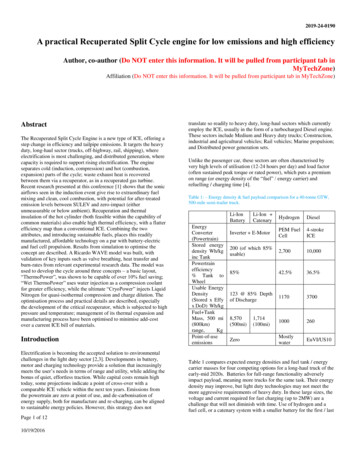
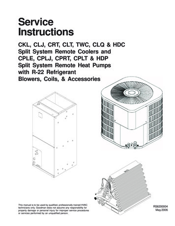
INSTALLATION INSTRUCTIONSR 410A Split System Air ConditionerINSPECT NEW UNITAfter uncrating unit, inspect thoroughly for hiddendamage. If damage is found, notify the transportationcompany immediately and file a concealed damageclaim.SAFETY CONSIDERATIONSConsult a qualified installer, service agency, or thedealer/distributor for information and assistance. Thequalified installer must use factory authorized kits andaccessories when modifying this product. Refer to theindividual instructions packaged with the kit or accessorywhen installing.The weight of the product requires careful and properhandling procedures when lifting or moving to avoidpersonal injury. Use care to avoid contact with sharp orpointed edges.Follow all safety codes. Wear safety glasses, protectiveclothing, and work gloves. Use a heat sinking material such as a wet rag during brazing operations. Keep a fireextinguisher available. Consult local codes and theNational Electric Code (NEC) for special requirements.Improper installation, adjustment, alteration, service ormaintenance can void the warranty.!WARNINGELECTRICAL SHOCK HAZARDFailure to turn off the main (remote) electrical disconnect device could result in personal injury ordeath.Before installing, modifying or servicing system,turn OFF the main (remote) electrical disconnectdevice. There may be more than one disconnectdevice. Lock out and tag switch with a suitablewarning label.!CAUTIONPROPERTY DAMAGE HAZARDFailure to follow this caution may result in property damageR 410A systems operate at higher pressures thanR 22 systems. When working with R 410A systems, use only service equipment and replacement components specifically rated or approvedfor R 410A service.LOCATIONCheck local codes for regulations concerning zoning,noise, platforms, and other issues.Locate unit away from fresh air intakes, vents, orbedroom windows. Noise may carry into the openingsand disturb people inside.Locate unit in a well drained area, or support unit highenough so that water runoff will not enter the unit.Locate unit away from areas where heat, lint, or exhaustfumes will be discharged onto unit (as from dryer vents).Locate unit away from recessed or confined areas whererecirculation of discharge air may occur (refer toCLEARANCES section of this document).Roof top installation is acceptable providing the roof willsupport the unit and provisions are made for waterdrainage and noise/vibration dampening.NOTE: Roof mounted units exposed to wind may requirewind baffles. Consult the manufacturer for additionalinformation.CLEARANCESNominal minimum clearances are 48 inches (1.2m)above unit for discharge air and 18 inches (457mm) oneach side of the coil for intake air. Clearance on any oneside of the coil (normally between unit and structure) maybe reduced to 6 inches (152mm). Nominal minimumclearances are based on a solid parallel object such as awall or roof overhang.The clearance may be reduced for a single object withsmall surface area, such as the end of a wall, outsidecorner of a wall, fence section, post, etc. As a generalrule, the minimum clearance from the unit should equalthe width of the object. For example, a 6 inch (152mm)fence post should be a minimum of 6 inches (152mm)from the unit.2Do not install unit under roof overhangs unless guttersare present. A minimum vertical clearance of 48 inches(1.2m) is required to the overhang.Inside corner locations on single story structures requireevaluation. Large overhanging soffits may cause airrecirculation in a corner area even though recommendedminimum clearances are maintained. As a guide, locatethe unit far enough out so that half of the discharge grilleis out from under the soffit.When placing two or more units side by side, provide aminimum of 18 inches (457mm) between units.Provide minimum service clearance of 24 inches(610mm) from control box corner and side service panel.Refer to Figure 1.421 01 5103 00
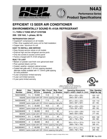
INSTALLATION INSTRUCTIONSR 410A Split System Air ConditionerFigure 1Clearances (various 2mm)6”wide 610mm)ServiceService18”18”(457mm)(457mm)421 01 5103 00Service18”18”(457mm)(457mm)3
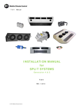
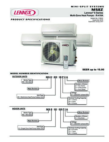
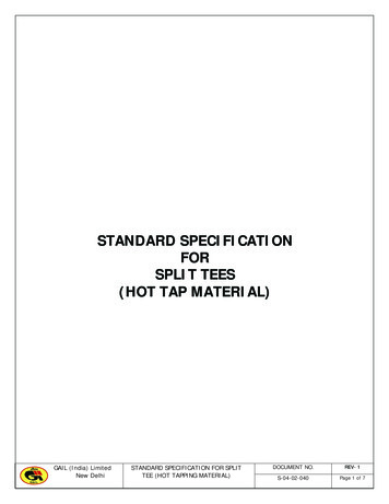
INSTALLATION INSTRUCTIONSR 410A Split System Air ConditionerUNIT SUPPORTNOTE: Unit must be level 2 degrees {a inch rise or fallper foot of run (10mm rise or fall per 305 mm of run) }orcompressor may not function properly.A. GROUND LEVEL INSTALLATIONThe unit must be level and supported above grade bybeams, platform, or a pad. Platform or pad can be ofopen or solid construction but should be of permanentmaterials such as concrete, bricks, blocks, steel, orpressure treated timbers approved for ground contact.Soil conditions must be considered so that the platformor pad does not shift or settle and leave the unit partiallysupported. Minimum pad dimensions are shown inFigure 2.If beams or an open platform are used for support, it isrecommended that the soil be treated or area begraveled to reduce the growth of grasses and weeds.To minimize vibration or noise transmission, it isrecommended that supports not be in contact with thebuilding structure. However, slabs on gradeconstructions with an extended pad are normallyacceptable.B. ROOF TOP INSTALLATIONThis type of installation is not recommended on woodframe structures where low noise levels are required.Supporting structure or platform for the unit must belevel. If installation is on a flat roof, locate unit minimum 6inches (152mm) above roof level.Place the unit over one or more load bearing walls. Ifthere are several units, mount them on platforms that areself supporting and span several load bearing walls.These suggestions are to minimize noise and vibrationtransmission through the structure. If the structure is ahome or apartment, avoid locating the unit overbedrooms or study.NOTE: When unit is to be installed on a bondedguaranteed roof, a release must be obtained from thebuilding owner to free the installer from all liabilities.C. FASTENING UNIT DOWNIf conditions or local codes require the unit be attached inplace, remove the knockouts in the base pan and installtie down bolts through the holes (refer to Figure 2).Contact local distributor for hurricane hold down detailsand the P.E. (Professional Engineer) certification, whenrequired.4CAUTION!PROPERTY DAMAGE HAZARDFailure to follow this caution may result in property damage.Inadequate unit support may cause excessivevibration, noise, and/or stress on the refrigerantlines, leading to refrigerant line failure.Figure 2Tie Down KnockoutsView From Topa” (10mm) dia. Tie Down KnockoutsIn Base Pan (2 places)BasePanDepthCBABase PanWidth x Depth@# @#Base Pan WidthInches (mm)Tie DownKnockoutsABC&w v!*(584 x 584)(197)(113)(457)@%n @%n(z v@!4(652 x 652)#!8 #!8(791 x 791)# , # ,(887 x 887)(230)(z(230)(z(230)(113) 2(584 x 584)@ X @ (540)(660 x 660)@ s#!2 #!2(165)(625) 2@*v(165)MinimumMounting PadDimensions@# X @#(722)(800 x 800)#% #%(889 x 889)421 01 5103 00
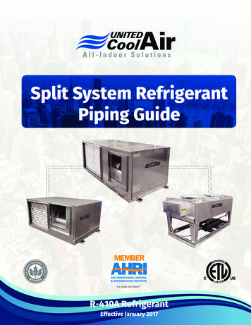
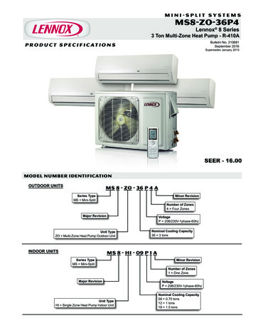
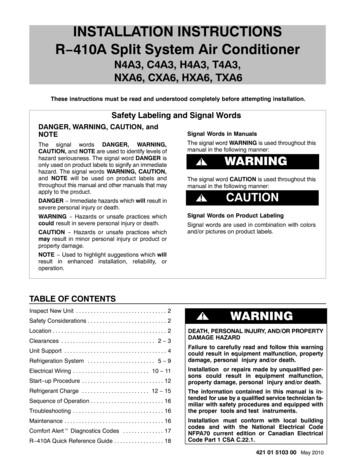
INSTALLATION INSTRUCTIONSR 410A Split System Air ConditionerREFRIGERATION SYSTEMA. COMPONENT MATCHESCheck to see that the proper system components are inplace, especially the indoor coil.R 410A outdoor units can only be used with R 410Aspecific indoor coils. If there is a refrigerant mis match,consult the indoor coil manufacturer to determine if arefrigerant conversion kit is available for the indoor coil.This outdoor unit is designed for use only with indoorcoils that utilize a TXV refrigerant metering device orPiston with Teflon ring metering device. If any other typeof metering device is installed on the indoor coil, consultthe indoor coil manufacturer to determine if a TXVconversion kit is available.Installing with TXVWhen installing a TXV on an indoor coil, follow theinstructions provided with the new TXV.A typical TXV installation is shown in Figure 3.Typical TXV InstallationFigure 3Installing with Indoor Piston cooling operation.Check piston size shipped with indoor unit to see if itmatches required indoor piston size.If it does not match, replace indoor piston with correctpiston size. (Indoor pistons are shipped with someoutdoor models in the accessory bag and are onlyqualified for Piston fan coils.)Example fan coils with piston: FEM4P, FSM4P, FSU4P(12 thru 4 ton).See Figure 4.When changing indoor piston, use a back up wrench.Hand tighten hex nut, then tighten with wrench 1/2 turn.Do not exceed 30 ft lbs.The indoor piston contains aTeflon ring (or seal) which is used to seat against theinside of distributor body, and must be installed properlyto ensure proper seating in the direction for coolingoperation.Indoor (cooling) PistonFigure 4BRASSHEX NUTDISTRIBUTORTEFLON SEALTEFLON RINGINDOORCOILEQUALIZERTUBEPISTONFLOW DTUBEBRASSHEX BODYSTRAINERTXVL10S01710 O’Clock2 O’ClockSENSING BULBSTRAPSUCTION TUBE7/8 IN. OD & SMALLER421 01 5103 00!CAUTIONPRODUCT OPERATION HAZARDFailure to follow this caution may result in improper productoperation.If using a TXV in conjunction with a single phase reciprocating compressor, a compressor start capacitor and relay arerequired. Consult outdoor unit pre sale literature for start assist kit part number.5
INSTALLATION INSTRUCTIONSR 410A Split System Air ConditionerB. REFRIGERANT LINE SETSThe refrigerant line set must be properly sized to assuremaximum efficiency and proper oil circulation.Refer to Product Specifications and Long LineApplications Guideline for line set sizing.NOTE: Total line set length must not exceed 200 feet(61m).A crankcase heater must be used when the refrigerantline length exceeds 80 feet (24.4m).If outdoor unit is more than 10 feet (3m) higher than theindoor coil, refer to the Long Line Applications Guidelinefor instructions.When the outdoor unit is higher than the indoor coil, thevertical separation must not exceed 100 feet (30m).When the outdoor unit is lower than the indoor coil, thevertical separation must not exceed 50 feet (15.2m).If it is necessary to add refrigerant line in the field, usedehydrated or dry, sealed, deoxidized, copperrefrigeration tubing. Do not use copper water pipe.Do not remove rubber plugs or caps from copper tubinguntil connections are ready to be made.Be extra careful when bending refrigeration tubing.Tubing can “kink” easily, and if this occurs, the entirelength of tubing must be replaced.WARNING!PERSONAL INJURY HAZARDFailure to relieve system pressure could result inpersonal injury and/or death.Relieve pressure and recover all refrigerant before servicing existing equipment, and before final unit disposal. Use all service ports and openall flow control devices, including solenoidvalves.Figure 5CAUTION!UNIT OPERATION HAZARDFailure to follow this caution may result in improper product operation.Do not leave system open to atmosphere any longer than absolutely required for installation. Internal system components especially refrigerantoils are extremely susceptible to moisture contamination. Keep ends of tubing sealed duringinstallation until the last possible moment.Routing and Suspending Refrigerant LinesOUTDOOR WALLJOISTINDOOR WALLCAULKLIQUID TUBEINSULATIONTHROUGH THE WALL6C. ROUTING AND SUSPENDING REFRIGERANTLINESRun refrigerant lines as straight and direct as possible,avoiding unnecessary bends and turns. Always insulatethe entire suction line. Both lines should be insulatedwhen routed through an attic or when routed through anunderground raceway.When routing refrigerant lines through a foundation or wall,do not allow refrigerant lines to come in direct contact withthe building structure. Make openings large enough so thatlines can be wrapped with extra insulation. Fill all gaps withRTV caulk. This will prevent noise transmission betweenthe tubing and the foundation or wall.Along floor or ceiling joists, suspend refrigerant lines sothat they do not contact the building structure, waterpipes, or ductwork. Use insulated or suspension typehangers. Metal straps must be at least 1” (25mm) wide toavoid cutting into the tube insulation. Keep the liquid andsuction lines separate. Refer to Figure 5.HANGER STRAP(AROUND SUCTIONTUBE ONLY)INSULATIONSUCTION TUBESUCTION TUBE1” (25mm)MINLIQUID TUBESUSPENSION421 01 5103 00
INSTALLATION INSTRUCTIONSR 410A Split System Air ConditionerUNIT OPERATION HAZARDrefrigerant charge sealed in the unit. Leave the servicevalves closed until all other refrigerant system work iscomplete or the charge will be lost. Leave the plugs inplace until line set tubing is ready to be inserted.Failure to follow this caution may result in improper product operation.Service valve bodies are brass and tube stubs arecopper.!CAUTIONDo not bury more than 36” (1m) of line set underground. Refrigerant may migrate to cooler buriedsection during extended periods of unit shut down, causing refrigerant slugging and possiblecompressor damage at start up.If ANY section of the line set is buried underground, provide a minimum 6” (152mm) verticalrise at the service valve.D. OUTDOOR UNIT HIGHER THAN INDOOR UNITProper oil return to the compressor should be maintainedwith suction gas velocity. If velocities drop below 1500fpm (feet per minute), oil return will be decreased. Tomaintain suction gas velocity, do not upsize verticalsuction risers.E. LIQUID LINE FILTER DRIEROutdoor units are shipped with an appropriate filter drierfor installation in the liquid line. Leave the plugs in thetube ends until the filter drier is installed. The optimallocation for the filter drier is close to the indoor coil.Install the filter drier with the arrow pointing towards theindoor coil. Refer to Figure 6.Figure 6Liquid Line Filter DrierInstalled at Indoor CoilFigure 7Service ValveSERVICE VALVEVALVE COREG. BRAZING CONNECTIONSNOTE: Remove valve core from schrader port on bothService Valves BEFORE brazing. This helps preventoverheating and damage to valve seals (refer to Figure 7).Replace valve core when brazing is completed.!WARNINGFIRE HAZARDFailure to remove refrigerant and oil charge before brazing could result in personal injury, death,and/or property damage.Refrigerant and oil mixture could ignite and burnas it escapes and contacts brazing torch. Makesure the refrigerant charge is properly removedfrom both the high and low sides of the system before brazing any component or lines.Clean line set tube ends with emery cloth or steel brush.Remove any grit or debris.Insert line set tube ends into service valve tube stubs.Apply heat absorbing paste or heat sink product betweenservice valve and joint. Wrap service valves with a heatsinking material such as a wet cloth.Braze joints using a Sil Fos or Phos copper alloy.!Filter Drier(arrow points towards indoor coil)CAUTIONPRODUCT DAMAGE HAZARD38 11 84Failure to follow this caution may result in product damage.F. SERVICE VALVESService valves are closed and tube stubs are pluggedfrom the factory. Outdoor units are shipped with aBraze with Sil Fos or Phos copper alloy on copper to copper joints and wrap a wet cloth aroundrear of fitting to prevent damage to TXV.421 01 5103 007
INSTALLATION INSTRUCTIONSR 410A Split System Air ConditionerH. EVACUATING LINE SET AND INDOOR COILThe unit is shipped with a factory refrigerant charge. Theliquid line and suction line service valves have been closedafter final testing at the factory. Do not disturb these valvesuntil the line set and indoor coil have been evacuated andleak checked, or the charge in the unit may be lost.NOTE: Do not use any portion of the factory charge forpurging or leak testing. The factory charge is for filling thesystem only after a complete evacuation and leak checkhas been performed.CAUTION!PRODUCT DAMAGE HAZARDFailure to follow this caution may result in product damage.Never use the outdoor unit compressor as a vacuum pump. Doing so may damage the compressor.Line set and indoor coil should be evacuated using therecommended deep vacuum method of 500 microns. Ifdeep vacuum equipment is not available, the alternatetriple evacuation method may be used by following thespecified procedure.If vacuum must be interrupted during the evacuationprocedure, always break vacuum with dry nitrogen.Deep Vacuum MethodThe deep vacuum method requires a vacuum pumpcapable of pulling a vacuum to 500 microns and avacuum gauge capable of accurately measuring thisvacuum level. The deep vacuum method is the mostpositive way of assuring a system is free of air and water.Watch the vacuum gauge as the system is pulling down.The response of the gauge is an indicator of the conditionof the system (refer to Figure 8).With no leaks in the system, allow the vacuum pump torun for 30 minutes minimum at the deep vacuum level.Deep Vacuum Gauge Respons
R 410A Split System Air Conditioner N4A3, C4A3, H4A3, T4A3, NXA6, CXA6, HXA6, TXA6 These instructions must be read and understood completely before attempting installation. DANGER, WARNING, CAUTION, and NOTE The signal words DANGER, WARNING, CAUTION, and NOTE are used to identify levels of hazard seriousness. The signal word DANGER isFile Size: 387KB