Transcription
INSTALLATION INSTRUCTIONSR 410A Variable Speed Split System Air ConditionerCVA9, HVA9, TVA9These instructions must be read and understood completely before attempting installation.TABLE OF CONTENTSPAGE NO.SAFETY CONSIDERATIONS . . . . . . . . . . . . . . . . . . . . . . . . . . . . . 1INSTALLATION RECOMMENDATIONS . . . . . . . . . . . . . . . . . . . . 2INSTALLATION . . . . . . . . . . . . . . . . . . . . . . . . . . . . . . . . . . . . . . . 2STEP 1 — CHECK EQUIPMENT AND JOB SITE . . . . . . . . . . . . . 2STEP 2 — INSTALL ON A SOLID, LEVEL MOUNTING PAD . . . 2STEP 3 — CLEARANCE REQUIREMENTS . . . . . . . . . . . . . . . . . 3STEP 4 — OPERATING AMBIENT . . . . . . . . . . . . . . . . . . . . . . . . 3STEP 5 — ELEVATE UNIT . . . . . . . . . . . . . . . . . . . . . . . . . . . . . . . 3STEP 6 — MAKE PIPING CONNECTIONS . . . . . . . . . . . . . . . . . . 3REFRIGERANT CONNECTIONS AND RECOMMENDEDLIQUID AND VAPOR TUBE DIAMETERS (IN.) . . . . . . . . . . . . . . 4STEP 7 — MAKE ELECTRICAL CONNECTIONS . . . . . . . . . . . . . 5STEP 8 — COMPRESSOR CRANKCASE HEATER . . . . . . . . . . . . 6AIRFLOW SETUP FOR OBSERVER FURNACEOR FCM4X FAN COIL . . . . . . . . . . . . . . . . . . . . . . . . . . . . . . . . . 6AIRFLOW SETUP FOR NON COMMUNICATING FAN COIL . . . 6AIRFLOW SETUP FOR NON COMMUNICATING FURNACES . . 6STEP 9 — INSTALL ACCESSORIES . . . . . . . . . . . . . . . . . . . . . . . 6STEP 10 — START UP . . . . . . . . . . . . . . . . . . . . . . . . . . . . . . . . . . 6STEP 11 — SYSTEM FUNCTIONS ANDSEQUENCE OF OPERATION . . . . . . . . . . . . . . . . . . . . . . . . . . . . 7STEP 12 — CHECK CHARGE . . . . . . . . . . . . . . . . . . . . . . . . . . . . 7REQUIRED CHARGE (VALUES IN LBS.)ADJUSTMENT FOR INDOOR COIL MODEL . . . . . . . . . . . . . . . . 8STEP 13 — PUMPDOWN & EVACUATION . . . . . . . . . . . . . . . . . 9MAJOR COMPONENTS . . . . . . . . . . . . . . . . . . . . . . . . . . . . . . . . . 9TROUBLESHOOTING . . . . . . . . . . . . . . . . . . . . . . . . . . . . . . . . . . 10FACTORY SUPPLIED MODEL PLUG INFORMATION . . . . . . . . . 10RESISTANCE VALUES VS TEMPERATURE . . . . . . . . . . . . . . . . . 11VARIABLE SPEED COMPRESSOR RESISTANCE . . . . . . . . . . . . . 12TROUBLESHOOTING . . . . . . . . . . . . . . . . . . . . . . . . . . . . . . . . . . 13FINAL CHECKS . . . . . . . . . . . . . . . . . . . . . . . . . . . . . . . . . . . . . . . 13CARE AND MAINTENANCE . . . . . . . . . . . . . . . . . . . . . . . . . . . . 13TECHNICAL LABELS . . . . . . . . . . . . . . . . . . . . . . . . . . . . . . . . . . 14R 410A QUICK REFERENCE GUIDE . . . . . . . . . . . . . . . . . . . . . . 18IMPORTANT: Effective January 1, 2015, all split system andpackaged air conditioners must be installed pursuant to applicableregional efficiency standards issued by the Department of Energy.Information in these installation instructions pertains only toCVA9, HVA9, TVA9 series units.SAFETY CONSIDERATIONSImproper installation, adjustment, alteration, service, maintenance,or use can cause explosion, fire, electrical shock, or otherconditions which may cause death, personal injury, or propertydamage. Consult a qualified installer, service agency, or yourdistributor or branch for information or assistance. The qualifiedinstaller or agency must use factory authorized kits or accessorieswhen modifying this product. Refer to the individual instructionspackaged with the kits or accessories when installing.Follow all safety codes. Wear safety glasses, protective clothing,and work gloves. Use quenching cloth for brazing operations.Have fire extinguisher available. Read these instructionsthoroughly and follow all warnings or cautions included inliterature and attached to the unit. Consult local building codes andcurrent editions of the National Electrical Code (NEC) NFPA 70.In Canada, refer to current editions of the Canadian electrical codeCSA 22.1.manuals, be alert to the potential for personal injury. Understandthese signal words; DANGER, WARNING, and CAUTION. Thesewords are used with the safety alert symbol. DANGER identifiesthe most serious hazards which will result in severe personal injuryor death. WARNING signifies hazards which could result inpersonal injury or death. CAUTION is used to identify unsafepractices which would result in minor personal injury or productand property damage. NOTE is used to highlight suggestionswhich will result in enhanced installation, reliability, or operation.!CAUTIONCUT HAZARDFailure to follow this caution may result in personal injury.Sheet metal parts may have sharp edges or burrs. Use care andwear appropriate protective clothing and gloves whenhandling parts.!WARNINGUNIT OPERATION AND SAFETY HAZARDFailure to follow this warning could result in personal injuryor equipment damage.R 410A refrigerant systems operate at higher pressures thanstandard R 22 systems. Do not use R 22 service equipmentor components on R 410A refrigerant equipment.WARNING!ELECTRICAL SHOCK HAZARDFailure to follow this warning could result in personalinjury or death.Before installing, modifying, or servicing system, mainelectrical disconnect switch must be in the OFF position.There may be more than 1 disconnect switch. Lock out andtag switch with a suitable warning label.Indoor Thermostat Control OptionsModelObserver WallControlStandardThermostatCVA9, HVA9,TVA9Yes*Yes**NOTE: TSTAT0201CW Communicating Wi-Fi wall control. Non Wi-Ficannot be used.All trademarks are the property of their respective owners. Wi-Fi is a regis tered trademark of Wi-Fi Alliance Corporation.* Version 5.0 software or newer.** Using standard thermostat limits functionality of system.Recognize safety information. This is the safety alert symbol !!When you see this symbol on the unit and in instructions orSpecifications subject to change without notice.421 01 5900 00 10/19/15
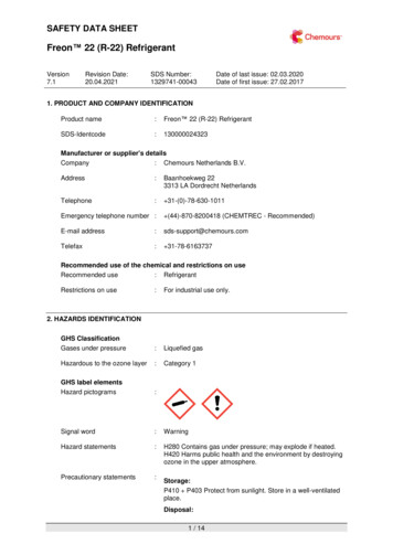
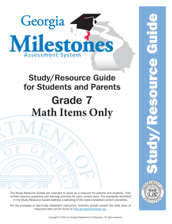
!WARNINGELECTRICAL HAZARD HIGH VOLTAGE!Failure to follow this warning could result in personal injuryor death.Electrical components may hold charge. DO NOT removecontrol box cover for 2 minutes after power has beenremoved from unit.CAUTION!EQUIPMENT DAMAGE HAZARDFailure to follow this caution may result in equipment damage.If proper lineset routing techniques are not followed, variablespeed systems can be susceptible to lineset transmitted noiseinside the dwelling and, in extreme cases, tubing breakage.OUTDOOR WALLPRIOR TO TOUCHING ELECTRICAL COMPONENTS:Verify zero (0) voltage at inverter connections shown oninverter cover.!INDOOR WALLCAULKWARNINGLIQUID TUBEINSULATIONTHROUGH THE WALLEXPLOSION HAZARDJOISTFailure to follow this warning couldresult in death, serious personal injury,and/or property damage.HANGER STRAP(AROUND SUCTIONTUBE ONLY)Never use air or gases containingoxygen for leak testing or operatingrefrigerant compressors. Pressurizedmixtures of air or gases containingoxygen can lead to an explosion.INSULATIONSUCTION TUBE1” (25.4 mm)MINLIQUID TUBESUSPENSIONA07588Fig. 1 Connecting Tubing InstallationInverter CoverIMPORTANT: The inverter cover should NEVER be removedbecause there is no reason to remove the inverter cover to accessthe inverter. The inverter has limited serviceability. Refer toService Manual for details on field replaceable parts. Areplacement cover is provided with a replacement inverter.INSTALLATION RECOMMENDATIONSIn some cases noise in the living area has been traced to gaspulsations from improper installation of equipment.1. Locate unit away from windows, patios, decks, etc. whereunit operation sound may disturb customer.2. In noise sensitive applications (such as bedrooms), when alineset is mounted to ceiling joists or floor joists, the outdoor unit must be located at least 10 ft (3.05 m) away. Ifthis is not possible, create a line set configuration withenough bends to provide 10 ft (3.05 m) of total line setlength outside the dwelling3. Ensure that vapor and liquid tube diameters are appropriatefor unit capacity.4. Run refrigerant tubes as directly as possible by avoiding unnecessary turns and bends.5. Leave some slack between structure and unit to absorb vibration.6. When passing refrigerant tubes through the wall, seal opening with RTV or other pliable silicon based caulk (see Fig.1).7. Avoid direct tubing contact with water pipes, duct work,floor joists, wall studs, floors, and walls.8. Do not suspend refrigerant tubing from joists and studs witha rigid wire or strap which comes in direct contact with tubing (see Fig. 1).9. Ensure that tubing insulation is pliable and completely surrounds vapor tube.10. When necessary, use hanger straps which are 1 in. wide andconform to shape of tubing insulation. (See Fig. 1.)11. Isolate hanger straps from insulation by using metal sleevesbent to conform to shape of insulation.421 01 5900 00SUCTION TUBEThe outdoor unit contains the correct amount of refrigerant chargefor operation with AHRI rated indoor units when connected by 15ft (4.57 m) of field supplied or factory accessory tubing.See Step 12 on page 7 for proper charging procedure.IMPORTANT: Liquid line size is 3/8 in. OD for all CVA9,HVA9, TVA9 applications. The maximum allowable equivalentline set length is 100 ft. (30.5 m).IMPORTANT: Always install the factory supplied liquid linefilter drier. Obtain replacement filter driers from your distributor orbranch.INSTALLATIONSpecifications for this unit in residential new construction marketrequire the outdoor unit, indoor unit (including metering device),refrigerant tubing sets, and filter drier listed in pre sale literature.There can be no deviation. Consult the Service Manual – AirConditioners and Heat Pumps Using R 410A Refrigerant to obtainrequired unit changes for specific applications and for R 22retrofit.Step 1 — Check Equipment and Job SiteUnpack UnitMove to final location. Remove carton taking care not to damageunit.Inspect EquipmentFile claim with shipping company prior to installation if shipmentis damaged or incomplete. Locate unit rating plate on unit cornerpanel. It contains information needed to properly install unit.Check rating plate to be sure unit matches job specifications.Step 2 — Install on a Solid, Level Mounting PadIf conditions or local codes require the unit be attached to pad, tiedown bolts should be used and fastened through knockoutsprovided in unit base pan. Refer to unit mounting pattern in Fig. 2to determine base pan size and knockout hole location.For hurricane tie downs, contact distributor for details and PE(Professional Engineer) Certification, if required.On rooftop applications, mount on level platform or frame. Placeunit above a load bearing wall and isolate unit and tubing set fromstructure. Arrange supporting members to adequately support unitSpecifications subject to change without notice.2
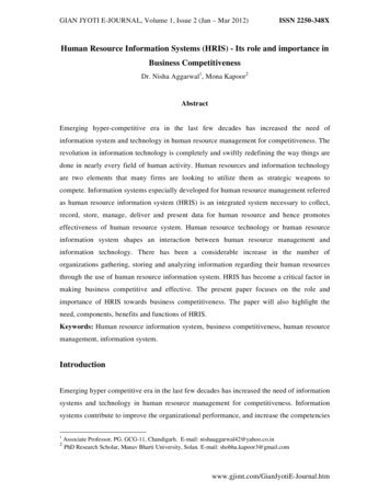
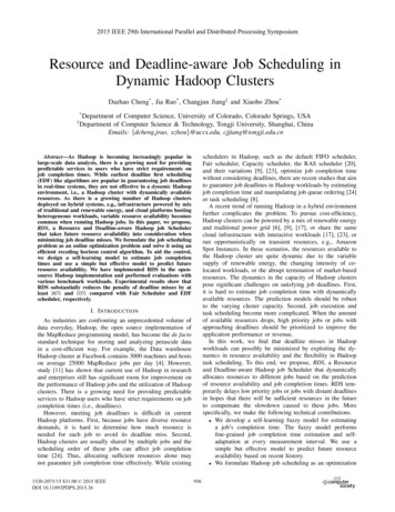
and minimize transmission of vibration to building. Consult localcodes governing rooftop applications.Roof mounted units exposed to winds above 5 mph may requirewind baffles. Consult the Service Manual Residential SplitSystem Air Conditioners and Heat Pumps Using R 410ARefrigerant for wind baffle construction.NOTE: Unit must be level to within 2 ( 3/8 in./ft, 9.5 mm/m.)per compressor manufacturer specifications.Step 3 — Clearance RequirementsWhen installing, allow sufficient space for airflow clearance,wiring, refrigerant piping, and service. Allow 24 in. (609.6 mm)clearance to service end of unit and 48 in. (1219.2 mm) (aboveunit. For proper airflow, a 6 in. (152.4 mm) clearance on 1 side ofunit and 12 in. (304.8 mm) on all remaining sides must bemaintained. Maintain a distance of 24 in. (609.6 mm) betweenunits. Position so water, snow, or ice from roof or eaves cannot falldirectly on unit.On rooftop applications, locate unit at least 6 in. (152.4 mm) aboveroof surface.3/8-in. (9.53 mm) Dia.Tie-down Knockouts inBasepan(2) Places!CAUTIONUNIT OPERATION HAZARDFailure to follow this caution may result in equipmentdamage or improper operation.Locate the unit in such a way that it is stable in allcircumstances including adverse weather conditions.Step 6 — Make Piping ConnectionsWARNING!PERSONAL INJURY AND UNIT DAMAGEHAZARDFailure to follow this warning could result in personal injury ordeath.Relieve pressure and recover all refrigerant before systemrepair or final unit disposal. Use all service ports and open allflow control devices, including solenoid valves.!CAUTIONUNIT DAMAGE HAZARDFailure to follow this caution may result in equipmentdamage or improper operation.Do not leave system open to atmosphere any longer thanminimum required for installation. POE oil in compressor isextremely susceptible to moisture absorption. Always keepends of tubing sealed during installation.View From TopA05177UNIT BASE PANDimension in. (mm)23 X 23(596 X 596)31.2 X 31.2(792 X 792)35 X 35(889 X 889)TIEDOWN KNOCKOUT LOCATIONS in. (mm)ABC7-13/16 (198)4-7/16 (102)18-1/8 (458)9-1/8 (232)6-9/16 (167)24-11/16 (627)9-1/8 (232)6-9/16 (167)28-7/16 (722)Fig. 2 Tie down Knockout LocationsStep 4 — Operating AmbientThe minimum outdoor operating ambient is 40 F (4.4 C) withObserver Wall Control, 55 F (12.8 C) with non communicatingsystems. The maximum outdoor operating ambient is 115 F(46.1 C). Compressor protections will prevent operation belowminimum ambient temperature range. The system may operate incooling up to 125 F (52 C) (52C) with significant reducedcapacity cutback above 115 F (46.1 C). Refer to Product Data“Detailed Cooling Capacity” table.Low ambient coolingoperation is not currently available.Step 5 — Elevate UnitElevate unit per local climate and code requirements to provideclearance above estimated snowfall level and ensure adequatedrainage of unit.!!CAUTIONUNIT DAMAGE HAZARDFailure to follow this caution may result in equipmentdamage or improper operation.If ANY refrigerant tubing is buried, provide a 6 in. (152.4mm) vertical rise at service valve. Refrigerant tubing lengthsup to 36 in. (914.4 mm) may be buried without furtherspecial consideration. Do not bury lines longer than 36 in.(914.4 mm).Outdoor units may be connected to indoor section using accessorytubing package or field supplied refrigerant grade tubing of correctsize and condition. For tubing requirements between 80 100 ft.(24.38 30.48 m), capacity and performance losses can occur.Follow the pipe sizing recommendations in the CVA9, HVA9,TVA9 Product data to manage these losses. This unit shall not beinstalled with greater than 100 ft (30.48 m) of equivalent linelength.Refer to Table 1 for field tubing diameters. No additionalaccessories are required for line lengths between 80 100 ft. (24.4 30.5 m) on this product.CAUTIONUNIT OPERATION HAZARDFailure to follow this caution may result in equipmentdamage or improper operation.Do not allow water and/or ice to build up in base pan.3Specifications subject to change without notice.421 01 5900 00
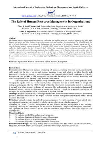
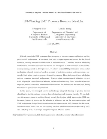
Table 1 – Refrigerant Connections and Recommended Liquid and Vapor Tube Diameters (in.)CVA9, HVA9, TVA9242536, 3748, 4960LIQUIDConnection Diame Tube ax (Rated) Diam eter3/47/87/8(1-1/8)(1-1/8)Connection Di ameter3/43/43/47/87/8Minimum Tube Diame ter5/85/85/83/43/4{ Units are rated with 25 ft. (7.6 m) of lineset. See Product Data sheet for performance data when using different size and length line sets.Notes:1. Do not apply capillary tube indoor coils to these units.Outdoor Unit Connected to Factory Approved IndoorUnitOutdoor unit contains correct system refrigerant charge foroperation with factory approved, AHRI rated indoor units whenconnected by 15 ft. (4.57 m) of field supplied or factory accessorytubing, and factory supplied filter drier. Check refrigerant chargefor maximum efficiency.NOTE: If the indoor furnace coil width is more than the furnacecasing width, refer to the indoor coil Installation Instructions fortransition requirements.Install Liquid Line Filter Drier IndoorRefer to Fig. 3 and install filter drier as follows:1. Braze 5 in. (127 mm) liquid tube to the indoor coil.2. Wrap filter drier with damp cloth.3. Braze filter drier to above 5 in. (127 mm) liquid tube.4. Connect and braze liquid refrigerant tube to the filter drier.Sweat ConnectionsUNIT DAMAGE HAZARDFailure to follow this caution may result in equipmentdamage or improper operation.S Use a brazing shieldS Wrap service valves with wet cloth or heat sink material.Use refrigerant grade tubing. Service valves are closed from factoryand ready for brazing. After wrapping service valve with a wetcloth, braze sweat connections using industry accepted methodsand materials. Consult local code requirements. Refrigerant tubingand indoor coil are now ready for leak testing. This check shouldinclude all field and factory joints.Evacuate Refrigerant Tubing and Indoor CoilCAUTION!CAUTION!CAUTION!UNIT DAMAGE HAZARDFailure to follow this caution may result in unit damage orimproper operation.Installation of filter drier in liquid line is required.UNIT DAMAGE HAZARDFailure to follow this caution may result in equipmentdamage or improper operation.Never use the system compressor as a vacuum pump.Refrigerant tubes and indoor coil should be evacuated using therecommended deep vacuum method of 500 microns. The alternatetriple evacuation method may be used. See Service Manual fortriple evacuation method. Always break a vacuum with drynitrogen prior to opening the refrigerant system for servicing.Deep Vacuum MethodThe deep vacuum method requires a vacuum pump capable ofpulling a vacuum of 500 microns and a vacuum gauge capable ofaccurately measuring this vacuum depth. The deep vacuum methodis the most positive way of assuring a system is free of air andliquid water. (See Fig. 4)Refrigerant Tubing connection OutdoorConnect vapor tube to fitting on outdoor unit vapor service valves(see Table 1).LEAK INSYSTEMMICRONSA05178Fig. 3 Liquid Line Filter Drier500045004000350030002500200015001000500VACUUM TIGHTTOO WETTIGHTDRY SYSTEM012345MINUTES67A95424A95424Fig. 4 Deep Vacuum Graph421 01 5900 00Specifications subject to change without notice.4
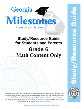
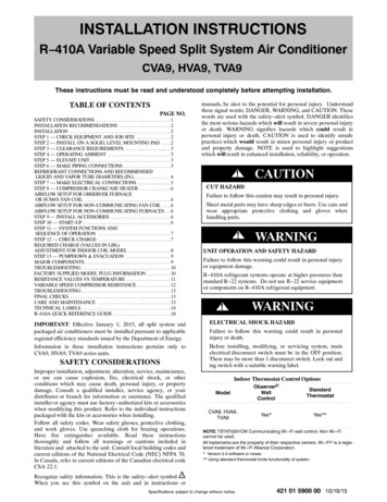
Final Tubing CheckObserver Control Wiring Observer WallIMPORTANT: Check to be certain factory tubing on both indoorand outdoor unit has not shifted during shipment. Ensure tubes arenot rubbing against each other or any sheet metal. Pay closeattention to feeder tubes, making sure wire ties on feeder tubes aresecure and tight.Connect four wires from Observer to communicating furnace / fancoil with communicating motor capability. Only two wires fromfurnace / fan coil DX (GR), DX (YL) are connected to theoutside inverter wiring GR (DX ), YL (DX ) (see Fig. 6).Connect C (WT) is recommended if wires are available (see Fig.6). This will reduce the chance of communication issues. Unusedlow voltage wires should be bundled together and terminated witha wire nut at each end. The end nearest indoor coil should beconnected to C terminal.IMPORTANT: This system requires the power supplied to theoutdoor unit, and the indoor unit, for the Observer Wall Control tocommunicate with the outdoor unit.Step 7 — Make Electrical ConnectionsWARNING!ELECTRICAL SHOCK HAZARDFailure to follow this warning could result in personalinjury or death.Do not supply power to unit with compressor terminal boxcover removed.WARNINGRDWTDXïDXïYLDX DX GRShielded cableYROAT’C’ connection optionalHumidifierThe unit cabinet must have an uninterrupted or unbrokenground to minimize personal injury if an electrical faultshould occur. The ground may consist of electrical wire ormetal conduit when installed in accordance with existingelectrical codes.Connect Ground and Power WiresConnect ground wire to ground connection in control box forsafety. Connect power wiring to contactor as shown in Fig. 5.DISCONNECTPER N. E. C. AND/ORLOCAL CODESTERMINALBLOCKFIELD POWERWIRINGFIELD GROUNDGROUNDLUGA14028Fig. 5 Line Power ConnectionsCHUMA150636Failure to follow this warning could result in personal injuryor death.5CFig. 6 Communicating Furnace or Fan Coil Wiring withCommunicating Variable Speed ACELECTRICAL SHOCK HAZARDWIRINGRC24vac CRemove access panel to gain access to unit wiring. Extend wiresfrom disconnect through power wiring hole provided and into unitcontrol box.!R’R’ not requiredWRoute Ground and Power WiresOutdoor UnitFurnace or Fan CoilWall ControlOBe sure field wiring complies with local and national fire, safety,and electrical codes, and voltage to system is within limits shownon unit rating plate. Contact local power company for correction ofimproper voltage. See unit rating plate for recommended circuitprotection device.NOTE: Operation of unit on improper line voltage constitutesabuse and could affect unit reliability. See unit rating plate. Do notinstall unit in system where voltage may fluctuate above or belowpermissible limits.NOTE: Use copper wire only between disconnect switch and unit.NOTE: Install branch circuit disconnect of adequate size per NECto handle unit starting current. Locate disconnect within sight fromand readily accessible from unit, per Section 440 14 of NEC.Connect Control Wiring Non Communicating4 wires are required when connecting CVA9, HVA9, TVA9 modelsto non communicating 2 stage thermostats. Use Fig. 7 Forrequired connections. Unit is configured by factory for Observer communicating control. To wire unit for non communicatingcontrol, disconnect the DX GN and DX YL wires fromgreen plug and connect appropriate wires to low voltage terminalblock. Use wire nuts to attach thermostat wire to low voltagechoke harness LVCH harness.General InformationUse 18 20 solid AWG color coded, insulated (355C minimum)wire for low voltage control wires. All wiring must be NEC Class2 and must be separated from incoming power leads.Installations using greater than 200 feet of low voltage wiringshould consult the Observer wall control manual for additionalguidelines regarding daisy chaining wiring method and terminatingresistors.Never route control wiring in parallel to high voltage power wireswhen possible as electrical noise may transfer and generatenuisance fault codes. Where low voltage control and high voltagewires must cross paths, do so at perpendicular angles to eliminatetransferred noise. If further communication issues exist, considerusing shielded low voltage wires and only connect shielding to Cterminal at end nearest indoor coil.Use furnace transformer, fan coil transformer, or accessorytransformer for control power requirement of system accessoriesexternal to the OD unit. The outdoor unit has its own transformerpower.Specifications subject to change without notice.421 01 5900 00
Final Wiring CheckIMPORTANT: Check factory wiring and field wire connections toensure terminations are secured properly. Check wire routing toensure wires are not in contact with tubing, sheet metal, etc. Ensurethat high and low voltage is separated where possible, to minimizeinduced noise from VFD to communication wiring.Indoor Control24 VAC HotGROY1Y1W1W2ssHeat Stage 3 W/W1Heat/CoolStage 2 Y/Y2FanAir ConditionerFan CoilRVS Cooling O/W2Heat/CoolStage 1 Y1/W2Y/Y224 VAC CommHumidifyRVS HeatingOutdoorCHUMY2GRDehumidify DHUMJumper WireRequred forSingle StageRemove J2 JumperFor Heat StagingDHRJ1 Jumper on Control BoardHumidifier(24 VAC)BFor installations with non communicating furnaces, set airflows to350 400 cfm/nominal ton in high stage and 70 80 percent of highstage airflow in low stage.S2A150213Indoor ControlW2Variable SpeedFurnaceY1Y1W/W1Y2Y/Y2GRAir ConditionerW2W1Y1Jumper WireRequred forSingle StageY2GRHDHUMCCOMAirflow Setup for Non communicating Fan CoilAirflow Setup for Non communicating FurnacesOutdoorSensorS1This system can only be installed with communicating indoor andObserver Wall Control TSTAT0201CW software version 5.0 orgreater. When using a Observer Wall Control, airflow isautomatically selected based on equipment size. The user has theoption of selecting Comfort, Efficiency and Max airflow forCooling modes. These should be selected based on balancebetween the homeowner’s comfort and energy consumptionexpectations. See Observer Wall Control Installation Instructionsfor additional available adjustments.Due to using a communicating control with the fan coil or thefurnace, dip switch adjustments are not necessary. The outdoorunit configuration and the indoor airflows are determined bycommunicating control setup.The system can be installed with a standard 2 stage thermostat andFVM4X fan coil without additional accessories. Select appropriateunit size on fan coil Easy select board.CCAirflow Setup for Observer Furnace or FCM4XFan Coil (communicating)Step 9 — Install AccessoriesNo refrigeration circuit accessories are required or are available forinstallation within the unit. External to the unit, the sameaccessories such as support feet, wind baffle etc., available on otherunits, can also be used on this line of product. For models utilizing23 inch x 23 inch base pans, it is recommended to use 5 supportfeet in order to fully support unit. See Fig. 8. Refer to theindividual Installation Instructions packaged with kits oraccessories when installing.RCHUMLO/BODOUTDOORSENSORGNDA150214Fig. 7 Low Voltage Wiring (Non Communicating)Step 8 — Compressor Crankcase HeaterThis compressor has an internal crankcase heater. Furnishpower to the unit a minimum of 24 hours before starting theunit for the first time.Upon initial start up of unit, status code 68 will be generated andsystem will operate at stage 2 for 11 minutes. This operation isimportant to system reliability and cannot be bypassed. Each timehigh voltage is removed and reapplied this behavior will berepeated.To furnish power to heater only, set thermostat to OFF and closeelectrical disconnect to outdoor unit.Power is not required to the indoor unit or Observer Wall Controlfor proper operation of heater. Crankcase heater will beintelligently energized as needed between operations, even whenthe Observer Wall Control or thermostat and indoor unit is notinstalled, as long as there is power to the outdoor unit.421 01 5900 00A14008Fig. 8 Recommended Support Feet Location(for 23 x 23 basepans)Step 10 — Start Up!CAUTIONUNIT OPERATION AND SAFETY HAZARDFailure to follow this caution may result in minor personalinjury, equipment damage or improper operation.Observe the following:1.Do not overcharge system with refrigerant.2.Do not operate unit in a vacuum or at negative pressure.3.Do not disable low pressure transducer or system safetydevices such as discharge thermistor or the high pressureswitch.4.Dome temperatures may be hot.5.Discharge thermistor is engaged tight on the discharge tube.Specifications subject to change without notice.6
!Outdoor Fan Motor OperationCAUTIONPERSONAL INJURY HAZARDFailure to follow this caution may result in personal injury.Wear safety glasses, protective clothing, and gloves whenhandling refrigerant.!CAUTIONENVIRONMENTAL HAZARDFailure to follow this caution may result in environmentaldamage.Federal regulations require that you do not vent refrigerant tothe atmosphere. Recover during system repair or final unitdisposal.The compact ECM outdoor fan motor is a variable speed brushlessDC (BLDC) motor that operates at speeds from 400 to 1050 RPM.The motor is a 3 phase permanent magnet type motor. Just likethe compressor, this motor speed is determined by the inverteroutput frequency and amplitude. (Fig. 9)Motor speed is controlled through the inverter board in the outdoorunit and no electronic module is attached. Motor speed is slowed asthe building load decreases, maintaining the proper condensingtemperature for both cooling and dehumidification. As the buildingload increases, the motor will increase speed until it is at maximumspeed at the maximum building load.At unit start up, there is a slight delay and thrust motion of the fanmotor/blade in the reverse direction, prior to ramping up the fanassembly.Step 11 — System Functions and Sequence ofOperationThe CVA9, HVA9, TVA9 models utilize either Observer WallCommunicating Wall Control or conventional thermostat. Whenusing Wall Control controls, a call for cooling will energize theoutdoor fan and compressor to run at lowest cooling demand. Ifthis does not satisfy cooling demand, the system will ramp up instages until it satisfies the demand. After coping with the higherdemand, the unit returns to lower capacity operation until thedemand is satisfied or until an increase in demand. When using aconventional thermostat, the thermostat controls the staging ofoutdoor unit.When all demand is satisfied, the compressor will shut off. As theunit operates at lower capacity, system vapor (suction) pressure willbe higher than it is during a standard single stage system operationor during a higher capacity operation.The Observer Wall Control displays the operation mode and faultcodes as specified in the troubleshooting section. See Table 6 forcodes and definitions.The conventional thermostat inputs are designed to work with mostindoor units. See AHRI for approved combinations. Connectionsare Y/Y2, Y1, R and C. Depending on thermostat and indoor unit,the system will operate at 1 or 2 capacities in cooling mode.NOTE: Only one code will be displayed on the outdoor unitcontrol board (the most recent, with the highest priority). Thelatest codes are stored and can be accessed via the Observer WallControl.Upon a call for cooling through the Observer Wall Control (or theY1 and/or Y2 connections in a non communicating system), theApplication Operation Control (AOC) board (see Fig. 17) willrequest a compressor speed and outdoor fan motor speed based onthe indoor space demand and outdoor conditions.If the conditions are correct for operation, the control board willallow the requested operation to begin, but if the control boarddetermines that the conditions are not correct, the board will decidewhat other operation nearing that condition is acceptable. Theinverter Motor Operational Control (MOC) then outputs thethree phase PWM signal and frequency that gently ramps thecompressor speed up to stage 2,
R 410A Variable Speed Split System Air Conditioner CVA9, HVA9, TVA9 These instructions must be read and understood completely before attempting installation. TABLE OF CONTENTS PAGE NO. SAFETY CONSIDERATIONS 1. INSTALLATION RECOMMENDATIONS 2. INSTALLATION 2. STEP 1 — CHECK EQUIPMENT AND JOB SITE 2. STEP 2 — INSTALL ON A SOLID, LEVEL MOUNTING PAD 2. STEP 3 — CLEARANCE .