Transcription
INSTALLATION & OPERATINGINSTRUCTIONSHeat PumpPool & SpaHeaterModel Series5350, 6350,6350HC, 8350,8350HC & 8360RCLI STEDUSFOR YOUR SAFETY: Do not store or use gasoline or other flammable vapors andliquids or other combustible materials in the vicinity of this or any other appliance. Todo so may result in an explosion or fire.NOTE: The instructions in this manual are for the use of qualified individuals specially trained and experiencedin the installation and maintenance of this type of equipment and related system components. Installation andservice personnel are required by some states to be licensed. Persons not qualified shall not attempt to install,service, or maintain this equipment.This manual should be maintained in legible condition and kept adjacent to the heat pump pool heater or in asafe place for future use.Catalog No. RP6000.552FEffective: 11-22-13Replaces: 06-28-13P/N 241377 Rev. 892-103778-03-10
Rev. 8 reflects the following:Changes to: Model Series on front cover, Tables A and B on page 9, Wiring Diagram on page 21, Wiring Diagram onpage 22.Additions: None.Deletions: None.2
Water Chemistry(Corrosive water voids all warranties)For your health and the protection of your pool equipment, it is essential that your water be chemicallybalanced. The following levels must be used as a guide for balanced water.Recommended Level(s)Water Temp. (Deg. F)pHTotal Alkalinity (PPM)Calcium Hardness (PPM)Salt (PPM)Free Chlorine (PPM)*Total Dissolved Solids (PPM)Fiberglass PoolsFiberglass SpasOther Pool & Spa Types7.3 to 7.47.3 to 7.47.6 to 7.868 to 8889 to 10468 to 104120 to 150120 to 150150 to 200200 to 4004500 MAXIMUM4500 MAXIMUM4500 MAXIMUM3000 MAXIMUM**3000 MAXIMUM**3000 MAXIMUM**200 to 3002 to 32 to 380 to 1202 to 3*Free Chlorine MUST NOT EXCEED 5 PPM!** In salt water chlorinated pools, the total TDS can be as high as 6000ppm. Occasional chemical shock dosing of the pool or spa water should not damage the heater providingthe water is balanced.Automatic chemical dosing devices and salt chlorinators are usually more efficient in heated water.Unless controlled, they can lead to excessive chlorine level which can damage your heater.Further advice should be obtained from your pool or spa builder, accredited pool shop, or chemicalsupplier for the correct levels for your water.3
CONTENTSWater ChemistryWarningsPay Attention to These TermsIntroductionInstallation ConsiderationsElectrical ConnectionsWater ConnectionsPressure DropControls & Indicator Lamps(Analog Models)System Start-UpControls (Digital Models)Digital Controls OperatingInstructionsTo Select Pool or Spa ModeTo Increase the Desired WaterTemperature (Pool or Spa Mode)To Lower Desired Water Temperature(Pool or Spa Mode)To Select Temperature in C or FHeat/Cool Operation(Model 6350HC Only)System Start-UpSeasonal Start-Up orAnnual CheckSummer ShutdownFreeze ProtectionSystem Drain-DownContinuous Pump OperationMaintenanceAir Coil CleaningCabinet Care (optional)Unplug Condensation Drain Holes35566799TroubleshootingService Call VerificationPower SupplyWater FlowTime Clock AdjustmentPlumbing DiagramsWiring Diagram — 208V/230VSingle-Phase — Analog ModelsWiring Diagram — 208V/230VSingle-Phase — Digital ModelsWiring Diagram — 208V/230VThree-Phase — Analog ModelsWiring Diagram — 208V/230VThree-Phase — Digital ModelsWiring Diagram — 460VThree-Phase — Analog ModelsInstalling a Remote ControlDeviceWiringHeater 5151515172122232425262626
WarningsDANGER:WARNING:CAUTION:NOTE:—Pay Attention to These TermsIndicates the presence of immediate hazards which will cause severe personal injury, deathor substantial property damage if ignored.Indicates the presence of hazards or unsafe practices which could cause severe personalinjury, death or substantial property damage if ignored.Indicates the presence of hazards or unsafe practices which could cause minor personalinjury or product or property damage if ignored.Indicates special instructions on installation, operation, or maintenance which are importantbut not related to personal injury hazards.This manual, as well as the pool/spa heat pump pool heater itself, contains ANSI-approved product safety signsand labels. Please read these signs and labels, as they convey important safety information about hazards thatmay be potentially present in and around the heat pump pool heater.CAUTION: Elevated water temperature can behazardous. The U.S. Consumer Product SafetyCommission has these guidelines:CAUTION: Improper chemical content in a swimming pool or spa can damage the heat pump poolheater. DO NOT add pool chemicals to the skimmer.This will damage the heat pump pool heater andcould void the heat pump pool heater warranty.ALWAYS follow the product manufacturer’s directions when adding any chemicals to your pool.2. Drinking of alcoholic beverages before or duringspa or hot tub use can cause drowsiness whichcould lead to unconsciousness and subsequentlyresult in drowning.WARNING: These heat pump pool heaters arecharged with R-410A refrigerant. Ensure that allservice work is done with gauges and equipmentsuitable for R-410A.1. Spa water temperatures should never exceed104 F (40 C). A temperature of 100 F (38 C) isconsidered safe for a healthy adult. Special caution is suggested for young children.3. Pregnant Women Beware! Soaking in water over102 F (39 C) can cause fetal damage during thefirst three months of pregnancy resulting in thebirth of a brain-damaged or deformed child.Pregnant women should stick to the 100 F (38 C)maximum rule.4. Before entering the spa or hot tub, users shouldcheck the water temperature with an accuratethermometer; spa or hot tub thermostats may errin regulating water temperatures by as much as4 F (2.2 C).5. Persons with a medical history of heart disease,circulatory problems, diabetes, or blood pressureproblems should obtain a physician's advicebefore using pools or hot tubs.6. Persons taking medications which induce drowsiness, such as tranquilizers, antihistamines, oranticoagulants, should not use spas or hot tubs.5
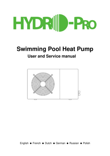
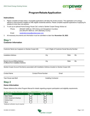
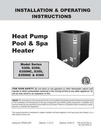
IntroductionInstallation ConsiderationsWARNING: Do not install the unit within 3 ft offossil fuel burning heaters. Air intake along thesides of this heat pump pool heater could disturbthe combustion process of the unit, and couldcause damage or personal injury. Mount the unit on a level, sturdy base, preferably aconcrete slab or blocks. The size of the base shouldbe at least 3 ft by 3 ft. You must install the 4 black rubber sound isolation pads (each 2 inches square) that ship withthe unit. The pads are shipped in a bag with theunions, gaskets and the I&O manual. Install padsunder the 4 corners of the unit to reduce vibration and sound transmission to the base.WARNING: This pool/spa heat pump pool heater isan electromechanical machine that incorporates apressurized refrigerant gas in a sealed system.ONLY trained and qualified service personnel areauthorized to install or service this equipment.Without proper training and knowledge of suchequipment, any attempt to install or service the unitcould result in serious injury or even death.This manual contains important information on theuse, maintenance and troubleshooting of your newheat pump pool heater. This unit must be properlyinstalled, maintained and operated for optimal performance.This heat pump pool heater is an extremely efficient,economical machine designed specifically for swimming pool heating. It is similar in design and operationto a typical residential air conditioning system. The unitemploys a hermetic motor/compressor operating in arefrigeration cycle to extract heat from ambient air anddeliver it to the circulating pool water.CAUTION: The unit’s supporting base must be highenough to keep it completely free of standing waterat all times.Situate the heat pump pool heater carefully to minimize installation costs while providing maximumefficiency of operation, and to allow adequate serviceaccess, as follows:As with all heat pump pool heaters, compared to othertypes of heaters such as gas or oil-fired, this heatpump pool heater has lower heating capacity on aBTUH/hr basis. As a result, it will be required to operate longer to accomplish the desired results. It may, atcertain times, operate as much as 24 hours per day.However, this should not be of concern to the owner,because the unit is designed to operate continuously.Even though it may operate continuously for manyhours, it will still heat the pool with greater economythan other types of fossil fuel heaters. For unrestricted air intake and service access,position each side of the unit at least 1 ft (30 cm)from walls, pipes and other obstructions.WARNING: This unit is designed for outdoor installation; DO NOT install it in an enclosed area such asa shed or garage. Place a cover or blanket over the pool at night andother non-use periods. This will keep evaporation, thecause of main heat loss, to a minimum, and will greatly reduce pool heating costs. During warmer weather,the cover may be required only at night. 6Recirculation of cold discharge air back into theevaporator coil will greatly reduce the unit’s heating capacity and efficiency.This unit features an ‘up-flow’ discharge for quietoperation. Air is pulled up through the evaporatorcoil and discharged through the top grill. Allow atleast 5 ft (1.5 m) clearance above the unit for unrestricted air discharge. DO NOT install the unitunder a porch or deck. Refer to Fig. 1.To minimize water piping, locate the unit as closeas possible to the existing pool pump and filter.If the location of the heat pump pool heater isbelow the water line of the pool, the water pressure switch might need to be adjusted or anexternal water flow switch might be needed.
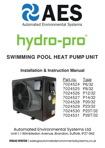
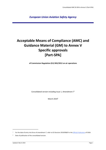
60”MIN3 FTMINGASHEATER AIR FLOW OUT12”MINAIRFLOWINAIRFLOWINFig. 1: Installation ClearancesIrrigation water should be directed away from theheat pump pool heater-water spray can damagethe heat pump pool heater.All wiring must be in accordance with the NationalElectrical Code, NFPA No. 70, latest edition, and allapplicable state and local codes. Wiring diagrams arelocated on pages 21 through 26.Rain water run offs- the heat pump pool heatercan withstand normal rain. Install rain gutters toprevent direct steams of rain water to the heatpump pool heater.NOTE: Refer to the National Electrical Code, Article680, for general requirements for swimming poolsand equipment, and to Article 440 for special considerations necessary for circuits supplying hermeticrefrigeration motor/compressors.It is important to keep the area next to the heatpump pool heater clear of shrubs, bushes andchemicals containers. They could prevent air fromcirculating fully through the heat pump pool heater,and will affect the operation of the heat pump poolheater or damage the heat pump pool heater. When installed in areas where freezing temperatures can be encountered, drain the water circuitto prevent possible freeze-up damage. See theFreeze Protection Section. For high wind installation requirements, refer tothe diagram on page 8. Electrical ConnectionsRefer to the unit rating plate below the control panel forprecise power requirements for your unit, and forampacity and over-current protection requirements.7Locate the equipment disconnect means within 3feet of the heater’s electrical enclosure, or asclose to the heater as possible. Always satisfyapplicable codes and standards.In sizing power wiring, be especially aware of upsizing requirements necessary due to wiringdistances. Always satisfy applicable codes andstandards.Electrical installation should be done by a licensedelectrician only.This unit is pre-wired to work with external control systems, heat-on-demand options and other external timeclock overrides. Refer to the external control system’sinstructions, and page 27 of this manual, for installation information.
8SEE HIGH WIND LOADRESTRAINT DETAIL 1COVERED UNITHEIGHT BETWEEN37-1/2” - 49-3/4”NOT INCLUDINGISOLATOR PADSGREATER THAN OR EQUAL TO 4” THICK SOLID CONCRETE 3000 P. S. I. OR GREATER LOAD RATINGPAD LENGTH GREATER THAN OR EQUAL TO UNIT LENGTH 6”PAD WIDTH GREATER THAN OR EQUAL TO UNIT WIDTH 6”PAD SPECIFICATION:THIS DRAWING USED AS A GRAPHICAL REPRESENTATION ONLY AND ITMAY NOT APPEAR EXACTLY LIKE YOUR SPECIFIC UNIT.2-1/2” MIN.SPACING TYP.27” MIN32” MAXRESTRAINTSPACING(4) VIBRATION ISOLATIONPADS TYP. EA. CORNERUNIT(2) 1/4” CONCRETE SCREWSLENGTH TO PENETRATE2-3/8” MINIMUM.HIGH WIND LOAD RESTRAINT DETAIL 1CONCRETE PAD(SEE PAD SPECS.)CLMINIMUM 18 GA. X 5” WIDE GALV. STEEL STRAP(G90) OR EQUIVALENT (MIN. QTY. OF 4 STRAPS)WITH (3) 1/2” LONG #12 SELF DRILLING SCREWSEACH STRAP (MIN. 1000 HR. COATING)186 MPH, 3 SEC. GUST IN ACCORDANCE WITH:ASCE 7-2010 CHAPTER 30 WIND LOADS - COMPONENTS AND CLADDINGFLORIDA BUILDING CODE 2010 - SECTION 1609 WIND LOADSFLORIDA BUILDING CODE 2010 - SECTION 1620 HIGH VELOCITY HURRICANE ZONES - WIND LOADS
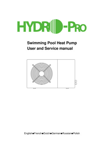
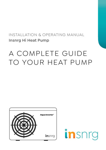
Model No.VAC in - Phase - HzMinimum CircuitAmpacity (A)5350208/230 - 1 - 6040.0208/230 - 1 - 6042.06350/6350HC208/230 - 1 - 608350/8350HCMinMax50605042.0208/230 - 3 - 608360Breaker Size (A)5034.0208/230 - 1 - 604042.05060605060Table A: Typical System Electrical Power RequirementsWater ConnectionsCAUTION: The heat pump pool heater inlet andoutlet connections are NOT interchangeable. Theymust be connected as instructed below.WATER IN1. Connect the heat pump pool heater in the returnwater line between the filter and the pool/spa. Seethe Plumbing Diagrams beginning on page 16.WATER OUTFig. 2: Water Connections2. Connect the filter outlet to the fitting markedWATER IN at the bottom front of the unit.4. In cold weather (freeze zone) areas, shutoff valves(ball or gate type) must be installed at the unit inletand outlet to facilitate service and cold weatherdrain-down.3. Connect the fitting marked WATER OUT to thereturn piping to the pool/spa. Unit inlet/outlet connection fittings are 2-inch PVC unions.5. Operate the pump and check the system for leaks.Water connections from the unit to the main returnline can be PVC pipe or flexible pipe approved forthe purpose and, in either case, should be at leastequal in size to the main pool/spa circulation piping.Pressure DropFor system pressure drop information, refer to Table Bbelow.Pressure Drop 0608079111113138350/8350HC/8360991113Note: Multiply the pressure drop in psi by 2.3067 to yield the pressure drop in Ft. H2O Head (TDH).Table B: Pressure Drop Across Heat Pump Pool Heater9
Defrost Switch: Prevents heat pump pool heateroperation if ambient air temperature falls below a predetermined safe minimum (approximately 42 F).WARNING: Install a check valve and/or a Hartfordloop AFTER the heat pump pool heater andBEFORE any chlorinating devices. Install any automatic chemical feeders AFTER the heat pump poolheater. Improper installation of any type of automatic chemical feeders can result in seriousdamage to, or premature failure of, the heatpump pool heater and will void the heat pumppool heater warranty.Delay Timer: Prevents compressor from short cycling,which could damage or destroy the hermeticmotor/compressor. Upon water temperature controlsatisfaction, or other circuit interruptions, this solidstate device will prevent compressor restart forapproximately 5 minutes.Controls & Indicator Lamps(Analog Models)Refrigerant Low Pressure Control: Stops the compressor if refrigerant suction (low side) pressure fallstoo low as a result of a malfunction, loss of charge orextreme cold conditions.Your analog heat pump pool heater incorporates safety controls and indicators to ensure its safe, reliableoperation (for models with digital controls, see page11).Indicator Lamps: There are 6 indicator lamps locatedon the unit control panel (see Fig. 3 below): Water Pressure Switch: Prevents operation when thepump is OFF. The unit requires 5 psi minimum pressure.Power (amber lamp): When lit, indicates power isapplied to the unit.NOTE: The heat pump pool heater will not run whenthe Remote position is selected on the Pool/Spaselector switch and there is no remote control system attached.Water Temperature Control: Pool/spa water temperature is controlled by the heat pump pool heaterthermostat on the unit control panel, which contains aswitch and 2 thermostats, one for setting a heat spatemperature and the other for a swimming pool temperature. The switch can operate an optional externalcontrol system, or can switch between thermostats forpool or spa. NOTE: The heat pump pool heater will not run whenthe Remote position is selected on the Pool/Spaselector switch and there is no remote control system attached.Water Flow (green lamp): When lit, indicates normal water flow.Heat Demand (green lamp): When lit, indicatesthe actual water temperature is below the targetwater temperature.Fig. 3: Indicator Lamps — Analog Models10
Compressor Delay Active (amber lamp): Undernormal operation, when lit, indicates compressoranti-short cycle timer is active. The fan will run butthe compressor will be OFF for 6 to 8 minutes.4. Allow the heat pump pool heater to operate for afew minutes to stabilize operating pressures and toallow various component temperatures to normalize.Defrost Active (red lamp): When lit, indicates unitis in defrost mode. Defrost mode occurs when icestarts to form on the outside coil. The fan will continue to run but the compressor will stay OFF (notheating) until weather conditions improve.5. Verify that the discharge air temperature is approximately 8 –10 cooler than the air entering the unit.If not, see the Troubleshooting Section.Controls (Digital Models)Low Pressure (red lamp): When lit, indicates failure in the refrigeration circuit. When this lamp isON, service is required. Call for service assistance.Your heat pump pool heater incorporates digital safetycontrols and indicators to ensure its safe, reliableoperation (for models with analog controls, see page10).System Start-UpWater Pressure Switch: Prevents operation when thepump is OFF. The unit requires 5 psi minimum pressure.1. Verify that the Power lamp is ON and that thepool/spa pump is running and circulating properly.Digital Water Temperature Control: The pool watertemperature is controlled by the heat pump poolheater’s digital control system, which gives you theoption of two settings: one for the desired spa temperature and the other for the desired pool temperature.Additionally, as mentioned earlier, the unit is compatible with most ‘2-wire’ and ‘3-wire’ control/automationsystems.2. Verify that the control panel Spa-Remote-Poolswitch is in the Remote (OFF) position; see Fig. 4below.3. Turn the control switch to either Pool or Spa toturn the system ON and raise the thermostat setting above the current water temperature. At thistime the 2 green lamps should illuminate. The fanand compressor should start up and run simultaneously.Fig. 5: Digital Water Temperature ControlDefrost Sensor: Prevents unit operation if ambient airtemperature falls below a predetermined safe minimum (approximately 42 –48 F, based on humidity).The compressor will shut OFF but the fan will continueto run.Fig. 4: Selector Knobs — Analog ModelsNOTE: The heat pump pool heater will not run whenthe Remote position is selected on the Pool/Spaselector switch and there is no remote control system attached.11Delay Timer: Prevents compressor from short cycling,which could damage or destroy the hermeticmotor/compressor. Upon water temperature controlsatisfaction, or other circuit interruptions, this solidstate device will prevent compressor restart forapproximately 5 minutes.
Heat/Cool Operation (Models6350HC and 8350HC Only)Digital Controls OperatingInstructionsThe heat/cool model is designed to both heat and coolthe pool. To select heat or cool mode, push the SETkey until H/C is displayed. Press the DOWN arrow keyto select heating (hea), or the UP arrow key to selectcooling (col). Set the desired setpoint temperature asdescribed earlier in this manual.The electronic board has the capability of memorizingtwo different programmed temperature settings as follows (refer to Fig. 5): For a pool, maximum 95 F (35 C)For a spa, maximum 104 F (40 C)NOTE: Once the control has been programmed tothe desired pool water temperature, the programmed temperature will be displayed forapproximately 5 seconds. The digital display willthen show the actual pool water temperature.To Select Pool or Spa ModeTo have access to either one of these programs, pressthe SET key until you see P S and by pressing theUP or DOWN key you can switch to POL or SPA.To Increase the Desired WaterTemperature (Pool or Spa Mode)NOTE: Remove the pool/spa blanket and turn onany fountains, sprays or other water features tospeed cooling.Push the SET key until you see POL or SPA. The programmed temperature will be displayed. Press the UParrow to increase the temperature setting one degreeat a time.When the unit has been operating in the heating modefor a few minutes, the discharge air temperatureshould be 8 –10 F cooler than the air entering the unit.To Lower the Desired WaterTemperature (Pool or Spa Mode)When the unit has been operating in the cooling modefor a few minutes, the discharge air temperatureshould be 8 –10 F warmer than the air entering theunit.Push the SET key until you see POL or SPA. The programmed temperature will be displayed. Press theDOWN arrow to decrease the temperature setting onedegree at a time.NOTE: Heating is more efficient during warmer daylight hours and cooling is more efficient during coolernight time hours.Once the control has been programmed to the desiredpool water temperature, the programmed temperaturewill be displayed for approximately 5 seconds. Thenthe digital display will display the actual pool watertemperature.To make the Board a Pool ONLY Board, call 800260-2758 for instructions.To Select Temperature in C or FPress the SET key until you see F C. By pressing theUP or DOWN key you can switch to F or C. Once thetemperature display mode has been programmed itwill be displayed for approximately 5 seconds, thenthe digital display will return to the actual pool watertemperature in the mode that you have chosen.12
Summer ShutdownSystem Start-UpIf you do not plan to use the heat pump pool heaterduring the summer months, secure and protect it asfollows:1. Verify that the Digital Board is displaying a temperature and the pool pump is running and water iscirculating properly.1. Turn the unit circuit breaker or disconnect switch toOFF.2. Verify that the Board is programmed so that thedesired temperature of the Pool and Spa is higherthan the displayed current water temperature.2. Leave the valves set the way they are unless additional circulation is required. DO NOT stop all flowthrough the heat pump pool heater.3. Allow the heat pump pool heater to operate for afew minutes to stabilize operating pressures and toallow various component temperatures to normalize.3. IMPORTANT: Remember to reset the valvesbefore the next heating season, or the unit will notoperate properly.4. Verify that the discharge air temperature is approximately 8 –10 F cooler than the air entering theunit. If not, see the Troubleshooting Section.Freeze ProtectionSeasonal Start-Up or AnnualCheckIf the unit is installed in a location subject to freezingconditions, it is important to protect the water circuitfrom freezing, just as should be done for the pump andfilter.NOTE: At the beginning of the heating season, orwhenever the pool water temperature is to be raisedseveral degrees, the pool pump and heat pump poolheater may need to operate continuously for severaldays. During summer months, only a few hours perday may be necessary, or none at all.System Drain-Down1. Turn the unit circuit breaker or disconnect switchto OFF.2. With the pool pump OFF, close the external shutoff valves and loosen the inlet and outlet waterunions to allow water to drain. Use a Wet/Dry Vacor air pressure to remove excess water.1. Remove leaves, pine needles, etc., from the evaporator coil. Clean the coil by gently applying a mildsolution of household liquid soap and water.3. Loosely re-attach the unions.2. Gently rinse the coil with water; DO NOT use highpressure.4. Cover the unit with a waterproof cover.3. Backwash or otherwise clean the pool filter. If necessary, clean the skimmer basket and pumpstrainer.Continuous Pump OperationIt is also possible in some areas to prevent unit freezedamage by operating the pump continuously duringfreezing weather. However, this results in significantlyhigher pump operating costs. Further, if a sustainedpower failure occurs, the unit MUST be drained anyway, or freeze damage could result.NOTE: If the pool pump and heat pump pool heatershut OFF before the water temperature is raised tothe desired level, you must lengthen the running timeof both. To do this, reset the time clock dial for thelonger running time, or manually operate the pumpwith the timer override switch. Since the heat pumppool heater capacity and efficiency are both greaterat higher ambient air temperatures, run time shouldbe set to take advantage of all daylight hours, whenthe air is generally warmer.4. Set the valves to ensure proper water flow throughthe unit.13
MaintenanceTroubleshootingIf your unit does not operate, or simply does not heatyour pool water, Fault Codes (digital models), or theindicator lamps (analog models) on the front controlpanel, can provide valuable clues as to what is wrong,and may even indicate precisely what the problem is.Always observe these codes (or lamps) before callinga service representative. By reporting on the telephone the Fault Codes (or which lamps are ON orOFF) that are showing, the service rep may be able tosolve the problem without the expense of a servicecall.NOTE: The heat pump pool heater MANUFACTURER IS NOT RESPONSIBLE for maintenanceadjustments.The following maintenance procedures are designedto keep your unit operating at a high level of reliability.Maintenance must be performed on a periodicbasis to maintain warranty coverage and preventsystem failures and performance degradation.Air Coil CleaningNOTE: If the compressor fails to start when energized, and there are no faults detected in the wiring,contact the factory for the appropriate “Hard StartKit.”Efficient operation depends on free circulation of airthrough the thin and tightly-spaced fins of the evaporator coil(s). The evaporator must be cleanedwhenever it has a buildup of dirt or debris.A. UNIT IS RUNNING, BUT NOT HEATINGCAUTION: To clean the fins, spray gently with agarden hose. DO NOT pressure wash. Doing sowill bend the fins and can void the warranty. Cabinet Care (optional)The cabinet is designed for outdoor use and requireslittle care. However, you can clean it if you wish. WARNING: Shut OFF electricity to the unit beforecleaning. Wash the cabinet with soap and water. Unplug Condensation Drain HolesThe unit extracts humidity from the air as it passesthrough the coil, similar to the way a cold drink outside“sweats” on a hot day. This condensation drains fromthe bottom of the unit.Is water flow through the unit adequate? Checkthe unit for obstructions, such as a clogged filterpump strainer, a dirty filter, or valves not positioned correctly.Is the ejected air from the unit 8 –10 F cooler thanincoming air? If so, the unit is extracting heat fromthe air and transferring it to the pool.Is water condensing on the evaporator and internal copper pipes? This is also evidence of heatremoval from the air. When the air is cool with lowhumidity, condensation may not be evident.How long has the unit been operating? During initial pool heating in cold weather, it may require aweek to elevate the water temperature to a comfortable level. Normally, it takes about 4 days.How many hours per day is the unit operating?Remember that the heat pump pool heater onlyoperates while the pool pump is running. Set thetime clock to permit 24 hour per day operation. Afterthe desired temperature is reached, return the unit tonormal operation of 8–10 hours per day.1. Routinely check to be sure the condensation drainholes in the base of the unit are not plugged withdirt or debris.2. If condensation becomes a problem, optional drainpans are available from your heat pump poolheater distributor or pool dealer.14
C. CONDENSATION SEEMS EXCESSIVENOTE: If the pool pump and heat pump pool heatershut OFF before the water temperature is raised tothe desired level, you must lengthen the running timeof both. To do this, reset the time clock dial for thelonger running time, or manually operate the pumpwith the timer override switch. Since the unit capacity and efficiency are both greater at higher ambientair temperatures, run time should be set to takeadvantage of all daylight hours, when the air is generally warmer. Heat pump pool heaters can produce a large amountof condensation (water) during operation. If you suspect that the unit is leaking:a. Use a pool chemistry test kit to confirm there is nochlorine in the condensation. Or,b. Shut the unit OFF and leave the filter pump running to see if the water stops dripping. If the waterstops dripping, the unit is not leaking.Is airflow through the unit being obstructed?Restrictions such as shrubbery, tall grass, dirtycoils, or any other obstruction to airflow will reduceperformance.Service Call VerificationNOTE: The Raypak Service number is 800-260-2758.Is the pool blanket/cover being used?Unblanketed pools can lose up to 10 degrees pernight compared to 4 degrees or fewer when ablanket is used. Without a blanket, the total heatgained during the day can be lost overnight.Before you make a service call, first determine if theproblem is: Are rapid heat losses occurring in some other way,such as high wind, spillage, rainfall, flow throughsolar panels at night, or a high water table? Is the temperature display or control panel Powerlamp ON? If not,
WARNING: These heat pump pool heaters are charged with R-410A refrigerant. Ensure that all service work is done with gauges and equipment suitable for R-410A. . types of heaters such as gas or oil-fired, this heat pump pool heater has lower heating capacity on a BTUH/hr basis. As a result, it will be required to oper- .