Transcription
Installation OperationMaintenanceSplit System Heat PumpCondensers6-20 Tons (R-410A)Model Numbers:(60 Hz)(50 *ATWA201E***ANovember 2009SSP-SVX14A-EN
Warnings, Cautions and NoticesWarnings, Cautions and Notices. Note that warnings, cautions and notices appear atappropriate intervals throughout this manual. Warnings are provided to alert installing contractorsto potential hazards that could result in personal injury or death. Cautions are designed to alertpersonnel to hazardous situations that could result in personal injury, while notices indicate asituation that could result in equipment or property-damage-only accidents.Your personal safety and the proper operation of this machine depend upon the strict observanceof these precautions.ATTENTION: Warnings, Cautions and Notices appear at appropriate sections throughoutthis literature. Read these carefully. WARNING: Indicates a potentially hazardous situation which, if not avoided, couldresult in death or serious injury. CAUTION: Indicates a potentially hazardous situation which, if not avoided, couldresult in minor or moderate injury. It could also be used to alert against unsafe practices.NOTICE: Indicates a situation that could result in equipment or property-damage onlyaccidents.ImportantEnvironmental Concerns!Scientific research has shown that certain man-made chemicals can affect the earth's naturallyoccurring stratospheric ozone layer when released to the atmosphere. In particular, several of theidentified chemicals that may affect the ozone layer are refrigerants that contain Chlorine, Fluorineand Carbon (CFCs) and those containing Hydrogen, Chlorine, Fluorine and Carbon (HCFCs). Not allrefrigerants containing these compounds have the same potential impact to the environment.Trane advocates the responsible handling of all refrigerants-including industry replacements forCFCs such as HCFCs and HFCs.Responsible Refrigerant Practices!Trane believes that responsible refrigerant practices are important to the environment, ourcustomers, and the air conditioning industry. All technicians who handle refrigerants must becertified. The Federal Clean Air Act (Section 608) sets forth the requirements for handling,reclaiming, recovering and recycling of certain refrigerants and the equipment that is used in theseservice procedures. In addition, some states or municipalities may have additional requirementsthat must also be adhered to for responsible management of refrigerants. Know the applicablelaws and follow them. WARNINGR-410A Refrigerant under Higher Pressure than R-22!The unit described in this manual uses R-410A refrigerant which operates at higher pressuresthan R-22 refrigerant. Use ONLY R-410A rated service equipment or components with this unit.For specific handling concerns with R-410A, please contact your local Trane representative.Failure to use R-410A rated service equipment or components could result in equipment orcomponents exploding under R-410A high pressures which could result in death, serious injury,or equipment damage. 2009 Trane All rights reservedSSP-SVX14A-EN
Warnings, Cautions and Notices WARNINGContains R-410A Refrigerant!System contains oil and refrigerant under high pressure. Recover refrigerant to relieve pressurebefore opening the system. See unit nameplate for refrigerant type. Do not use non-approvedrefrigerants, refrigerant substitutes, or refrigerant additives. Failure to follow proper proceduresor the use of non-approved refrigerants, refrigerant substitutes, or refrigerant additives couldresult in death or serious injury or equipment damage.Important:DO NOT release refrigerant to the atmosphere! If adding or removing refrigerant isrequired, the service technician must comply with all federal, state, and local laws.Important:One copy of this document ships inside the control panel of each unit and iscustomer property. It must be retained by the unit’s maintenance personnel. WARNINGPersonal Protective Equipment (PPE) Required!Installing/servicing this unit could result in exposure to electrical, mechanical and chemicalhazards. Before installing/servicing this unit, technicians MUST put on all Personal ProtectiveEquipment (PPE) recommended for the work being undertaken. ALWAYS refer to appropriateMSDS and OSHA guidelines for proper PPE. When working with or around hazardous chemicals, ALWAYS refer to appropriate MSDS andOSHA guidelines for information on allowable personal exposure levels, proper respiratoryprotection and handling recommendations. If there is a risk of arc or flash, technicians MUST put on all Personal Protective Equipment (PPE)in accordance with NFPA70E for arc/flash protection PRIOR to servicing the unit.Failure to follow recommendations could result in death or serious injury.This booklet describes proper installation, operation, and maintenance procedures for air cooledsystems. By carefully reviewing the information within this manual and following the instructions,the risk of improper operation and/or component damage will be minimized.It is important that periodic maintenance be performed to help assure trouble free operation. Amaintenance schedule is provided at the end of this manual. Should equipment failure occur,contact a qualified service organization with qualified, experienced HVAC technicians to properlydiagnose and repair this equipment.Important:All phases of this installation must comply with the NATIONAL, STATE & LOCALCODES. In addition to local codes, the installation must conform with NationalElectric Code -ANSI/NFPA NO. 70 LATEST REVISION.Any individual installing, maintaining, or servicing this equipment must be properly trained,licensed and qualified.SSP-SVX14A-EN3
Table of ContentsModel Number Description . . . . . . . . . . . . . . . . . . . . . . . . . . . . . . . . . . . . . . . . . . . . . . 6General Information . . . . . . . . . . . . . . . . . . . . . . . . . . . . . . . . . . . . . . . . . . . . . . . . . . . . 7Installation Checklist . . . . . . . . . . . . . . . . . . . . . . . . . . . . . . . . . . . . . . . . . . .Unit Inspection . . . . . . . . . . . . . . . . . . . . . . . . . . . . . . . . . . . . . . . . . . . . . . .Inspection Checklist . . . . . . . . . . . . . . . . . . . . . . . . . . . . . . . . . . . . . . . . . . . .Initial Leak Test . . . . . . . . . . . . . . . . . . . . . . . . . . . . . . . . . . . . . . . . . . . . . . .Lifting Recommendations . . . . . . . . . . . . . . . . . . . . . . . . . . . . . . . . . . . . . . .77777Pre-Installation . . . . . . . . . . . . . . . . . . . . . . . . . . . . . . . . . . . . . . . . . . . . . . . . . . . . . . . . . 9Clearances . . . . . . . . . . . . . . . . . . . . . . . . . . . . . . . . . . . . . . . . . . . . . . . . . . . 9Unit Mounting . . . . . . . . . . . . . . . . . . . . . . . . . . . . . . . . . . . . . . . . . . . . . . . . 9Snow Belt Recommendations . . . . . . . . . . . . . . . . . . . . . . . . . . . . . . . . . . 10Refrigerant Piping . . . . . . . . . . . . . . . . . . . . . . . . . . . . . . . . . . . . . . . . . . . . 10Dimensional Data . . . . . . . . . . . . . . . . . . . . . . . . . . . . . . . . . . . . . . . . . . . . . . . . . . . . . . 11Electrical Data . . . . . . . . . . . . . . . . . . . . . . . . . . . . . . . . . . . . . . . . . . . . . . . . . . . . . . . . . 15Installation . . . . . . . . . . . . . . . . . . . . . . . . . . . . . . . . . . . . . . . . . . . . . . . . . . . . . . . . . . . . 18Refrigerant Piping Guidelines . . . . . . . . . . . . . . . . . . . . . . . . . . . . . . . . . .Refrigerant Piping Procedures (Outdoor Units) . . . . . . . . . . . . . . . . . . . .Refrigerant Piping Procedure (Indoor Unit) . . . . . . . . . . . . . . . . . . . . . . .Leak Check . . . . . . . . . . . . . . . . . . . . . . . . . . . . . . . . . . . . . . . . . . . . . . . . . .Insulating and Isolating Refrigerant Lines . . . . . . . . . . . . . . . . . . . . . . . . .Refrigerant Charging Procedure . . . . . . . . . . . . . . . . . . . . . . . . . . . . . . . .Liquid Charging . . . . . . . . . . . . . . . . . . . . . . . . . . . . . . . . . . . . . . . . . . . . . .Electrical Wiring . . . . . . . . . . . . . . . . . . . . . . . . . . . . . . . . . . . . . . . . . . . . .Unit Power Supply . . . . . . . . . . . . . . . . . . . . . . . . . . . . . . . . . . . . . . . . . . .Field Wiring- ReliaTel Control . . . . . . . . . . . . . . . . . . . . . . . . . . . . . . . . .Field Wiring - Sensors . . . . . . . . . . . . . . . . . . . . . . . . . . . . . . . . . . . . . . . . .Refrigerant Circuit . . . . . . . . . . . . . . . . . . . . . . . . . . . . . . . . . . . . . . . . . . . .181820212222242525252728Charging Charts . . . . . . . . . . . . . . . . . . . . . . . . . . . . . . . . . . . . . . . . . . . . . . . . . . . . . . . 29Pre-Start . . . . . . . . . . . . . . . . . . . . . . . . . . . . . . . . . . . . . . . . . . . . . . . . . . . . . . . . . . . . . . 33Control Circuit Features . . . . . . . . . . . . . . . . . . . . . . . . . . . . . . . . . . . . . . . 33Installation Checklist . . . . . . . . . . . . . . . . . . . . . . . . . . . . . . . . . . . . . . . . . . 33Start-Up . . . . . . . . . . . . . . . . . . . . . . . . . . . . . . . . . . . . . . . . . . . . . . . . . . . . . . . . . . . . . . 35Service Test Modes ReliaTel Controls . . . . . . . . . . . . . . . . . . . . . . . . . . . . . . . . . 40Test Modes . . . . . . . . . . . . . . . . . . . . . . . . . . . . . . . . . . . . . . . . . . . . . . . . . 40Troubleshooting . . . . . . . . . . . . . . . . . . . . . . . . . . . . . . . . . . . . . . . . . . . . . . . . . . . . . . . 41Trouble Shooting ReliaTel Controls . . . . . . . . . . . . . . . . . . . . . . . . . . . .System Status Checkout Procedure . . . . . . . . . . . . . . . . . . . . . . . . . . . . . .Simultaneous Heat and Cool Failure . . . . . . . . . . . . . . . . . . . . . . . . . . . . .Resetting Cooling and Heating Lockouts . . . . . . . . . . . . . . . . . . . . . . . . .Zone Temperature Sensor (ZTS) Service Indicator . . . . . . . . . . . . . . . . .44142424344SSP-SVX14A-EN
Programmable & Digital Zone Sensor Test . . . . . . . . . . . . . . . . . . . . . . . 46Maintenance . . . . . . . . . . . . . . . . . . . . . . . . . . . . . . . . . . . . . . . . . . . . . . . . . . . . . . . . . . 47Monthly . . . . . . . . . . . . . . . . . . . . . . . . . . . . . . . . . . . . . . . . . . . . . . . . . . . .Annually (Cooling Season) . . . . . . . . . . . . . . . . . . . . . . . . . . . . . . . . . . . . .Coil Cleaning . . . . . . . . . . . . . . . . . . . . . . . . . . . . . . . . . . . . . . . . . . . . . . . .Maintenance Log . . . . . . . . . . . . . . . . . . . . . . . . . . . . . . . . . . . . . . . . . . . . .47474749Warranty . . . . . . . . . . . . . . . . . . . . . . . . . . . . . . . . . . . . . . . . . . . . . . . . . . . . . . . . . . . . . 50For Commercial Unitary Equipment Rated Under 20 Tons and Related Accessories . . . . . . . . . . . . . . . . . . . . . . . . . . . . . . . . . . . . . . . . . . . . . . . . . . . 50Commercial Equipment Rated 20 Tons and Larger and Related Accessories(Parts Only) . . . . . . . . . . . . . . . . . . . . . . . . . . . . . . . . . . . . . . . . . . . . . . . . . 51Wiring Diagram Matrix . . . . . . . . . . . . . . . . . . . . . . . . . . . . . . . . . . . . . . . . . . . . . . . . . 52SSP-SVX14A-EN5
Model Number DescriptionTWA090D300AA123456789 101112Model Number DescriptionAll products are identified by a multiple-character model number that precisely identifies a particular type ofunit. An explanation of the alphanumeric identification code is provided. Its use will enable the owner/operator, installing contractors, and service engineers to define the operation, specific components, andother options for any specific unit.Note: When ordering replacement parts or requesting service, be sure to refer to the specific model number,serial number, and DL number (if applicable) stamped on the unit nameplate.Digits 1 - 3: Product TypeTWA Split System Heat Pump Outdoor UnitDigits 4 - 6: Nominal Gross Cooling Capacity (MBh)073 6 Tons (60 hz)090 7½ Tons (60 hz)120 10 Tons (60 hz)180 15 Tons (60 hz)240 20 Tons (60 hz)061 5 Tons (50 Hz)076 6.25 Tons (50 Hz)101 8.33 Tons (50 Hz)156 13 Tons (50 Hz)201 16.7 Tons (50 Hz)Digit 7: Major Development SequenceD Single CircuitE Dual CircuitDigits 8: Electrical Characteristics3 208-230/60/34 460/60/3W 575/60/3D 380-415/50/3K 380/60/3Digits 9 - 10: Factory Installed Options0R ReliaTel, no LCI Board0T ReliaTel, no LCI Board with Black Epoxy Coated Coil0U ReliaTel, with LCI Board0W ReliaTel, with LCI Board and Black Epoxy Coated CoilHR Hailguard with ReliaTel, no LCI BoardHT Hailguard with ReliaTel, no LCI Board with Black Epoxy Coated CoilHU Hailguard with ReliaTel, with LCI BoardHW Hailguard withReliaTel, with LCI Board and Black Epoxy Coated CoilDigits 11: Minor Design SequenceA Current Design SequenceDigits 12: Service DigitA Current Service Digit6SSP-SVX14A-EN
General InformationInstallation procedures should be performed in the sequence that they appear in this manual. Donot destroy or remove the manual from the unit.The manual should remain weather-protected with the unit until all installation procedures arecomplete.Note: It is not the intention of this manual to cover all possible variations in systems that mayoccur or to provide comprehensive information concerning every possible contingency thatmay be encountered during an installation. If additional information is required or if specificproblems arise that are not fully discussed in this manual, contact your local sales office.Installation ChecklistAn "Installation Checklist" is provided at the end of the installation section of this manual. Use thechecklist to verify that all necessary installation procedures have been completed. Do not use thechecklist as a substitute for reading the information contained in the manual. Read the entiremanual before beginning installation procedures.Unit InspectionInspect material carefully for any shipping damage. If damaged, it must be reported to, and claimsmade against the transportation company. Compare the information that appears on the unitnameplate with ordering and submittal data to ensure the proper unit was shipped. Availablepower supply must be compatible with electrical characteristics specified on componentnameplates. Replace damaged parts with authorized parts only.Inspection ChecklistTo protect against loss due to damage incurred in transit, complete the following checklist uponreceipt of the unit.1. Inspect individual pieces of the shipment before accepting the unit. Check for obvious damageto the unit or packing material.2. Inspect the unit for concealed damage before it is stored and as soon as possible after delivery.Concealed damage must be reported within 15 days. If concealed damage is discovered, stopunpacking the shipment. Do not remove damaged material from the receiving location. Takephotos of the damage if possible. The owner must provide reasonable evidence that thedamage did not occur after delivery.3. Notify the carrier’s terminal of damage immediately by phone and by mail. Request animmediate joint inspection of the damage by the carrier and the consignee.4. Notify the sales representative and arrange for repair. Do not repair the unit until the damageis inspected by the carrier’s representative.Initial Leak TestAll TWA units are shipped with a holding charge of nitrogen in each circuit. Remove the servicepanel(s) shown in Figure 3, p. 12 - Figure 5, p. 14. Locate the liquid line or suction line service valvefor each circuit. Install gauges to determine if the circuits are still pressurized. If not, the charge hasescaped. Repair as required to obtain a leak-free circuit.Lifting RecommendationsNOTICEEquipment Damage!Use spreader bars to prevent lifting straps from damaging the unit. Install bars between liftingstraps. This will prevent the straps from crushing the unit cabinet or damaging the unit finish.SSP-SVX14A-EN7
General Information WARNINGImproper Unit Lift!Each of the cables (chains or slings) used to lift the unit must be capable of supporting the entireweight of the unit. Lifting cables (chains or slings) may not be of the same length. Adjust asnecessary for even unit lift. Other lifting arrangements may cause equipment or property-onlydamage. Failure to properly lift unit could result in death or serious injury. Refer to Table 1 andTable 2 for unit weight.Before preparing the unit for lifting, estimate the approximate center of gravity for lifting safety.Because of placement of internal components, the unit weight may be unevenly distributed.Approximate unit weights are given in Table 1 and Table 2.Table 1.TWA Unit & Corner Weights — kg (50 Hz)TonsModel 8616.7TWA201E4413821141206681Table 2.Net Max(kg)Corner WeightsShippingMax (kg)TWA Unit & Corner Weights — lbs (60 Hz)Corner WeightsTonsModel No.ShippingMax (lbs)Net 520219218119020TWA240E981848254266147181The crated unit can be moved using a forklift of suitable capacity. For lifting the unit, attach liftingstraps or slings securely to the lifting holes at each corner. Use spreader bars to protect the unitcasing from damage. Test lift the unit to determine proper balance and stability.8SSP-SVX14A-EN
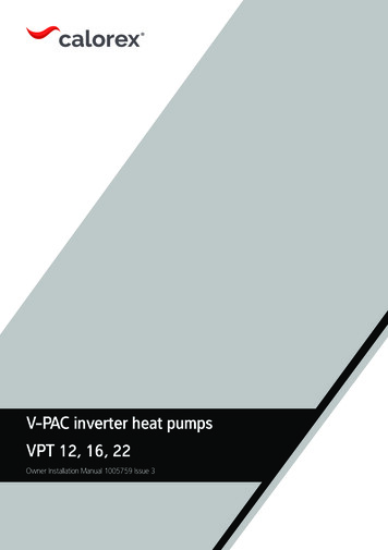
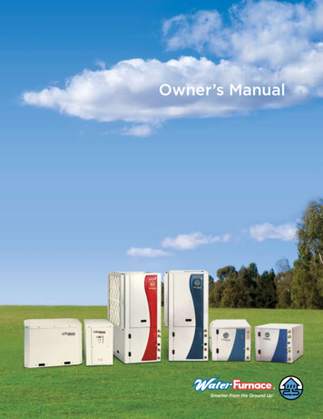
Pre-InstallationClearancesProvide enough space around the unit to allow unrestricted access to all service points. Refer toFigure 3, p. 12 through Figure 5, p. 14 for unit dimensions and minimum required service and freeair clearances. Observe the following points to ensure proper unit operation.1. Do not install the unit under a low overhang. Outdoor discharge must not be restricted. SeeNotes in Figure 3, p. 12 through Figure 5, p. 14.Important:Do not obstruct outdoor discharge air. This can result in warm air recirculationthrough the coil.2. Do not locate the unit in a position where runoff water can fall into the fan discharge openings.3. Outdoor intake air is supplied from three or four sides of the unit. Adhere to the minimumrequired clearances given in Figure 3, p. 12 through Figure 5, p. 14.Unit Mounting WARNINGMounting Integrity!Ensure that the roof structure supports are strong enough to support the weight of the unit andany accessories. Failure to do so could result in death or serious injury or possible equipment orproperty-only damage.Rooftop MountingIf the unit will be roof mounted, determine forcertain that the structure is strong enough tosupport the unit and any required accessories.Unit weights are given in Table 1 and Table 2,p. 8. The unit should be elevated on a level, fieldfabricated four-inch steel or wood 4" x 4"mounting frame. Complete the frame and secureit into position before lifting the unit to the roof.The mounting frame must support a minimum ofthree of the unit’s four sides and should span roofsupports to distribute the load on the roof.Figure 1. Roof Mounted UnitOutdoor UnitGas (Suction)Line - InsulatedLiquid LineInsulatedUnit MountingChannels6”RadiusElevation(Mounting Frame)Ground Level MountingFor ground level installation, the unit base shouldbe adequately supported and hold the unit nearlevel. The installation must meet the guidelinesset forth in local codes. The support shouldextend two inches beyond the unit base channelsat all points. The unit and support must beisolated from any adjacent structure to preventpossible noise or vibration problems. Anyground level location must comply with requiredclearances given in Figure 3, p. 12 throughFigure 5, p. 14.SSP-SVX14A-ENRoofConstructionRoof TrussingCeiling9
Pre-InstallationSnow Belt RecommendationsIn regions where deep snow is encountered, raise the unit a minimum distance of 8 to 12 inchesabove the mounting surface. This will reduce the risk of snow blocking the coil and improves runoffof water produced during the defrost cycle. Avoid locating the unit where snow tends to drift. Snowaccumulations must be removed from around the unit immediately to prevent drastic efficiencyreduction. A snow drift barrier may be constructed around the unit to prevent snow blockage.Clearance between the snow barrier and the unit must comply with the clearances given inFigure 3, p. 12 through Figure 5, p. 14.Refrigerant Piping WARNINGR-410A Refrigerant under Higher Pressure than R-22!The unit described in this manual uses R-410A refrigerant which operates at higher pressuresthan R-22 refrigerant. Use ONLY R-410A rated service equipment or components with this unit.For specific handling concerns with R-410A, please contact your local Trane representative.Failure to use R-410A rated service equipment or components could result in equipment orcomponents exploding under R-410A high pressures which could result in death, serious injury,or equipment damage.NOTICERoof Damage!System contains oil and refrigerant under high pressure. Roofs should be protected fromexposure to oils and refrigerant in the system. If rooftop is not protected damage to the roof mayoccur.Structural PreparationImportant:10Refer to local building codes for proper installation. All installation must comply withlocal building codes.SSP-SVX14A-EN
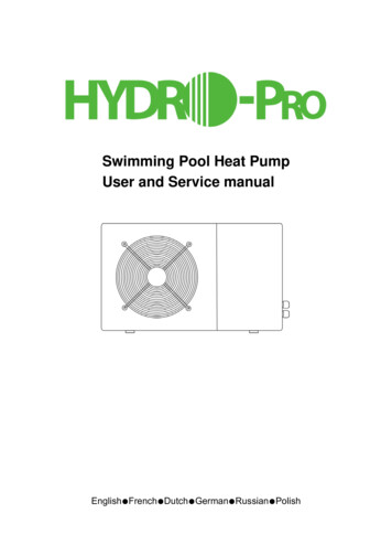
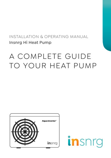
Dimensional DataFigure 2. TWA Quick ReferenceHHWDDWTWA 061, 073, 076, 090TWA101, 120TWA 156, 180, 201, 240H39.125 (993.8)39.125 (993.8)45.125 (1146.1)W42.125 (1070)52.125 (1324)95.5 (2425.7)D36 (914.4)40 (1016)45.875 (1165.2)Note: Full dimensional data available on next pages.SSP-SVX14A-EN11
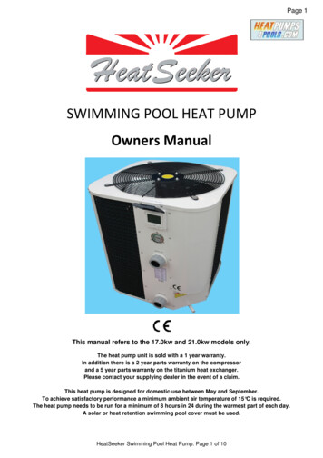
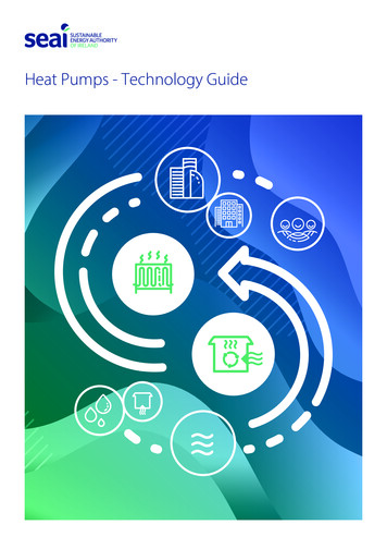
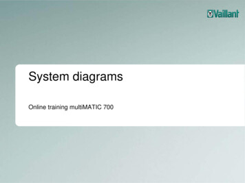
Dimensional DataFigure 3. TWA061, 073, 076, 090 Heat Pump, Single CompressorSEE NOTE 3NOTES:1. ACCESS OPENING IS FOR FIELD INSTALLED BAYLOAM ACCESSORY.2. MINIMUM CLEARANCE FOR PROPER OPERATION IS 36" ( 914.4) FROMWALLS, SHRUBBERY, PRIVACY FENCES ETC. MINIMUM CLEARANCEBETWEEN ADJACENT UNITS IS 72" (1828.8). RECOMMENDED SERVICECLEARANCE 48" (1219.2)3. TOP DISCHARGE AREA SHOULD BE UNRESTRICTED FOR 100" (2540)MINIMUM. UNIT SHOULD BE PLACED SO ROOF RUN-OFF WATER DOESNOT POUR DIRECTLY ON UNIT4. OUTDOOR AIR TEMPERATURE SENSOR OPENING (DO NOT BLOCK OPENING)SERVICE PANELHAIL GUARD(OPTIONAL)SEE NOTE 4SERVICE CLEARANCE48" (1219.2) (SEE NOTE 2FOR CLEARANCE)HAIL GUARD(OPTIONAL)35 15/16"(912.8)WITH HAIL GUARD33 15/16"(862)LINE VOLTAGECONTROL WIRING36 3/8"(923.9)29 13/16"(757.2)SEE NOTE 1REFRIGERANT ACCESS39 3/16"(995.4)26 15/16"(684.2)SERVICE PANEL14 3/8"(365.1)8 5/16"5 5/8"(211.1)(143)1/16"(1.6)LIQUID LINE6"(152.4)6"(152.4)2" (50.8)21 11/16"(550.9)SUCTION LINE41 1/16"(1043)33 13/16"(858.8)42 1/8"(1070)WITH HAIL GUARDSERVICE PANEL SIDE3" (76.2)34 3/4"40 3/4" (882.7)(1035)4 3/16"(106.4)1 13/16"(46)123 1/16" (77.8)7/16" (11.1) DIA. ISOLATOR MOUNTINGHOLES (OUTSIDE HOLES - 4 PLACES)BOTTOMOF UNIT27 11/16"(703.3)2 5/16"(58.7)SSP-SVX14A-EN
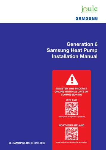
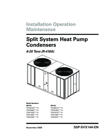
Dimensional DataFigure 4. TWA101, 120 Heat Pump, Single CompressorSEE NOTE 3NOTES:1. ACCESS OPENING IS FOR FIELD INSTALLED BAYLOAM ACCESSORY.2. MINIMUM CLEARANCE FOR PROPER OPERATION IS 36" (914.4) FROMWALLS, SHRUBBERY, PRIVACY FENCES ETC. MINIMUM CLEARANCEBETWEEN ADJACENT UNITS IS 72" (1828.8). RECOMMENDED SERVICECLEARANCE 48" (1219.2)3. TOP DISCHARGE AREA SHOULD BE UNRESTRICTED FOR 100" (2540)MINIMUM. UNIT SHOULD BE PLACED SO ROOF RUN-OFF WATER DOESNOT POUR DIRECTLY ON UNIT4. OUTDOOR AIR TEMPERATURE SENSOR OPENING (DO NOT BLOCK OPENING)SERVICE PANELSEE NOTE 4HAIL GUARD(OPTIONAL)SERVICE CLEARANCE48" (1219.2) (SEE NOTE 2FOR CLEARANCE39 15/16"(1014.4)WITH HAIL GUARD4 1/4" (108)HAIL GUARD(OPTIONAL)1 1/4" (31.7)LINE VOLTAGE37 15/16"(963.6)CONTROL WIRING42 5/16"35 3/4" (1074.7)(908)5 9/16"(141.3)SEE NOTE 1REFRIGERANT ACCESS44 3/4"(1136.6)SERVICE PANEL32 7/8"(835)8 1/4"(209.5)1/16" (1.6)LIQUID LINESUCTION LINE25 11/16"(652.5)6" (152.4)4" (101.6)6" (152.4)37 11/16"(957.3)4 3/8" (111.1)14 5/16"(363.5)1 13/16" (46)2 7/8" (73)50 15/16"(1293.8)51 15/16"(1319.2)WITH HAIL GUARDSERVICE PANEL SIDE3" (76.2)7/16" (11.1) DIA. ISOLATOR MOUNTINGHOLES (OUTSIDE HOLES - 4 PLACES)44 3/4"50 3/4" (1136.6)(1289)BOTTOMOF UNIT3 13/16"(96.8)2 3/16"(55.6)SSP-SVX14A-EN31 11/16"(805)1 11/16"(42.9)13
Dimensional DataFigure 5. TWA156, 180, 201, 240 Heat Pump, Dual CompressorSEE NOTE 2NOTES:1. MINIMUM CLEARANCE FOR PROPER OPERATION IS 36" (914.4) FROMWALLS, SHRUBBERY, PRIVACY FENCES ETC. MINIMUM CLEARANCEBETWEEN ADJACENT UNITS IS 72" (1829). RECOMMENDED SERVICECLEARANCE 48" (1219.2)2. TOP DISCHARGE AREA SHOULD BE UNRESTRICTED FOR 100" (2540)MINIMUM. UNIT SHOULD BE PLACED SO ROOF RUN-OFF WATER DOESNOT POUR DIRECTLY ON UNIT3. OUTDOOR AIR TEMPERATURE SENSOR OPENING (DO NOT BLOCK OPENING).HAIL GUARD(OPTIONAL)SEE NOTE 3SERVICE CLEARANCE48" (1219.2) (SEE NOTE 1FOR CLEARANCE)DETAIL A46"(1168.4)WITH HAIL GUARDSERVICE PANEL44 3/16"(1122.4)95 7/16"(2424.112)WITH HAIL GUARDHAIL GUARD(OPTIONAL)HAIL GUARD(OPTIONAL)45 1/8"(1146.2)SERVICEPANEL1/16"(1.6)41 3/8"(1051)9"(228.6)93 5/16"(2370.1)25 11/16"(652.5)9"(228.6)9 1/4" (235)6 13/16" (173)7/16" (11.1) ( DIA. ISOLATOR MOUNTINGHOLES (OUTSIDE HOLES - 4 PLACES)CONTROL WIRINGLINE VOLTAGESERVICE PANEL SIDEREFRIGERANT ACCESSBOTTOM OF UNIT3" (76.2)87"(2210)93"(2362.2)1 3/16" (30.2)36 7/8"(936.6)2 3/16" 6 13/16"(55.6) (173)41 1/2"(1054.1)41 5/8"39 7/8" (1057.3)(1012.8)14 1/2" 14 5/8" 12 5/8"(368.3) (371.5) (320.7)5 5/8" 4 1/4"(143) (108)SUCTION LINESLIQUID LINES15/16" (23.8)3 11/16" (94)6 5/16" (160.3)FRONT DETAIL ADIMENSIONAL DETAIL14SSP-SVX14A-EN
Electrical DataTable 3.Electrical Characteristics — Motors — Heat Pumps — 50HzCompressor MotorCondenser Fan MotorAmpsUnit 380/41511.95.8Table 4.Unit Wiring — Heat Pumps — 50 HzTonsUnitModel No.Unit OperatingVoltage RangeMaximum CircuitAmpacityMaximum Fuse Size orMaximumCircuit 2.04016.7TWA201ED380/41545.460(a) HACR type circuit breaker per NEC.SSP-SVX14A-EN15
Electrical DataTable 5.Electrical Characteristics — Compressor and Condenser Fan Motors — Heat Pumps — 60HzCompressor MotorCondenser Fan MotorAmpsTons67½10152016Unit Model 2575313.780257512.05.1SSP-SVX14A-EN
Electrical DataTable 6.Tons67½101520Unit Wiring — Heat Pumps —60 HzUnit Model No.Unit OperatingVoltage RangeMinimum CircuitAmpacityMaximum Fuse Size orMaximum 40EK342-41861.870TWA240EW518-63234.840(a) HACR type circuit breaker per NEC.SSP-SVX14A-EN17
InstallationRefrigerant Piping GuidelinesFigure 6. Allowable elevation difference: Cooling only TWA above indoor unitContact manufacturer for reviewAcceptable suction-riser heightbased on total suction-line length(TWA above indoor unit)Figure 7.Allowable elevation difference: TWA below indoor unitContact manufacturer for reviewTWAAcceptable liquid-riser heightbased on total liquid-line length(TWA below indoor unit)Note: Route refrigerant piping for minimum linear length, minimum number of bends and fittings(no reducers) and minimum amount of line exposed to outdoor ambients.Refrigerant Piping Procedures (Outdoor Units) WARNINGR-410A Refrigerant under Higher Pressure than R-22!The unit described in this manual uses R-410A refrigerant which operates at higher pressuresthan R-22 refrigerant. Use ONLY R-410A rated service equipment or components with this unit.For specific handling concerns with R-410A, please contact your local Trane representative.18SSP-SVX14A-EN
InstallationFailure to use R-410A rated service equipment or components could result in equipment orcomponents exploding under R-410A high pressures which could result in death, serious injury,or equipment damage.Each TWA unit ships with a holding charge of dry nitrogen The nitrogen should be removed andthe entire system evacuated (at the proper time) to avoid possible contamination.1. Remove the compressor service access panel.2. Locate the liquid and suction line service valves. Check that the piping connection stubs on thevalves (Figure 8) line up properly with the holes in the unit cabinet.Figure 8. Outdoor Units - Refrigerant Piping (with dry nitrogen)3. Remove the refrigerant connection seal caps and open the service valve slowly to release thenitrogen from the unit.NOTICESystem Component Damage!Do not remove the seal caps from refrigerant connections, or open the service valves untilprepared to braze refrigerant lines to the connections. Excessive exposure to atmosphere ( 5min.) may allow moisture or dirt to contamin
For specific handling concerns with R-410A, please contact your local Trane representative. Failure to use R-410A rated service equipment or components could result in equipment or components exploding under R-410A high pressures which could result in death, serious injury, or equipment damage.