Transcription
ENGLISHCode9828093076Edit. 07/2018INSTRUCTION AND MAINTENANCE MANUALDRYERSQPNC-75 (BE6) - QPNC-100 (BE7)- QPNC-125 (BE7,5) QPNC-150 (BE9) - QPNC-200 (BE10) - QPNC-250 (BE10S)READ THIS MANUAL CAREFULLY BEFORE CARRYING OUT ANY OPERATIONS ON THEDRYER.Cod. 9828093076 02 - Edition 07/2018 - 102
ENGLISHCONTENTSPART A: INFORMATION FOR THE USER1.0GENERAL CHARACTERISTICS2.0INTENDED USE3.0OPERATION4.0GENERAL SAFETY STANDARDS5.0DESCRIPTION OF DANGER SIGNALS6.0DANGER ZONES7.0SAFETY DEVICES8.0POSITION OF PLATES9.0DRYERS ROOM10.0TRANSPORT AND S AND TECHNICAL DATA14.0MACHINE ILLUSTRATION15.0SCRAPPING THE DRYERSPART B: INFORMATION RESERVED FOR TECHNICALLY SKILLED PERSONNEL16.0PARTIAL ROUTINE MAINTENANCE17.0TROUBLE-SHOOTING AND EMERGENCY REMEDIES18.0STARTING UPATTENTION: THERE IS A COPY OF THE WIRING DIAGRAM INSIDE THE ELECTRIC PANELADDRESSES OF ASSISTANCE CENTRESIn the event of breakdown or malfunction of the dryer, switch it off and do not tamper with it. If repairs are needed, applyonly to a technical assistance centre approved by the manufacturer and insist on the use of original spare parts. Failureto comply with the above may endanger the safety of the machine.INTRODUCTIONKeep this manual with care for future consultation; the use and maintenance manual is an integral part on thedryer. Read this manual carefully before carrying out any operations on the dryer.The installation of the dryer and all operations involving it must be performed in conformity with the regulationsin force concerning electric plants and personal safety.CHARACTERISTICS AND SAFETY PRECAUTIONSBEFORE REMOVING THE PROTECTIVE GUARDS TO CARRY OUT ANY MAINTENANCE ON THE MACHINE, SWITCH OFF THE ELECTRICPOWER SUPPLY AND DISCHARGE THE RESIDUAL PRESSURE INSIDE THE UNIT.ALL WORK ON THE ELECTRIC PLANT, HOWEVER SLIGHT, MUST BE CARRIED OUT BY PROFESSIONALLY SKILLED PERSONNEL.The manufacturer does not accept responsibility for damage caused as a result of negligence of failure to abide by theinstructions given above.THIS MACHINE IS NOT SUITABLE FOR EXTERNAL INSTALLATIONTHIS MACHINE CORRESPOND TO THE ESSENTIAL SAFETY REQUIREMENTS FORESEEN FROM THEEUROPEAN STANDARD (2006/42 CE).THE LUBRICATING LIQUIDS AND OTHER EVENTUAL FLUIDS MUST NOT BE DISCHARGED IN THEENVIRONMENT. THESE POLLUTING AND HAZARDOUS PRODUCTS MUST COMPULSORY BE DISPOSED BYCHARGING AUTHORISED AND SPECIALISED FIRMS ACCORDING TO THE DIFFERENT TYPOLOGY OFPRODUCT.DIFFERENTIATE THE COMPRESSOR COMPONENTS ACCORDING TO THE DIFFERENT CONSTRUCTIONMATERIALS (PLASTIC, COPPER, IRON, OIL FILTER, AIR FILTER ECC )2 - Edition 07/2018 Cod. 9828093076 02 -
ENGLISH1.0 GENERAL CHARACTERISTICSThe dryer is a chilling machine with direct expansion and dry evaporator.The air to be dried is sent to the heat exchanger in which the water vapour present is condensed: the condensategathers in the separator and is discharged outside through a steam trap.2.0 INTENDED USEThe dryer has been built to dry the compressed air for industrial use. The dryer cannot be used in premises where thereis a risk of fire or explosion or where work is carried out which releases substances into the environment which aredangerous with regard to safety (for example: solvents, inflammable vapours, alcohol, etc.).In particular the appliance cannot be used to produce air to be breathed by humans or used on direct contact withfoodstuffs. These uses are allowed if the compressed air produced is filtered by means of a suitable filtering system(Consult the manufacturer for these special uses.)This appliance must be used only for the purpose for which it was specifically designed. All other uses are to beconsidered incorrect and therefore unreasonable. The Manufacturer cannot be held responsible for any damage resultingfrom improper, incorrect or unreasonable use.3.0 OPERATIONThe gaseous refrigerant coming from the evaporator (4) is sucked by the refrigeration compressor (1) and it is pumpedinto the condenser (2). This one allows its condensation, eventually with the help of the fan (3); the condensed refrigerantpasses through the dewatering filter (8) and it expands through the capillary tube (7) and goes back to the evaporatorwhere it produces the refrigerating effect.Due to the heat exchange with the compressed air which passes through theevaporator against the stream, the refrigerant evaporates and goes back to the compressor for a new cycle.The circuit is equipped with a bypass system for the refrigerant; this intervenes to adjust the available refrigeratingcapacity to the actual cooling load. This is achieved by injecting hot gas under the control of the valve (9): this valvekeeps constant the pressure of the refrigerant in the evaporator and therefore also the dew point never decreases below(32 F / 0 C) in order to prevent the condensate from freezing inside the evaporator. The dryer runs completelyautomatically; it is calibrated in the factory for a dew point of 37,4 F (3 C) and therefore no further calibrations arerequired.DRYER FLOW DIAGRAMAIR OUTLETAIR INLETCONDENSATEAUTO DRAIN1)2)3)4)5)6)7)REFRIGERANT COMPRESSORCONDENSERMOTOR FANEVAPORATORDEMISTER CONDENSATE SEPARATORIMPURITY TRAPEXPANSION CAPILLARY TUBE8)9)10)11)13)REFRIGERANT FILTERHOT GAS BYPASS VALVEAIR-TO-AIR EXCANGERDIGITAL CONTROLLERCONDENSATE DRAIN4.0 GENERAL SAFETY STANDARDThe appliance may be used only by specially trained and authorized personnel.Any tampering with the machine or alterations not approved beforehand by the Manufacturer relieve the latter ofresponsibility for any damage resulting from the above actions.The removal of or tampering with the safety devices constitutes a violation of the European Standards on safety.ALL WORK ON THE ELECTRIC PLANT, HOWEVER SLIGHT, MUST BE CARRIED OUT BY PROFESSIONALLY SKILLED PERSONNEL.Cod. 9828093076 02 - Edition 07/2018 - 3
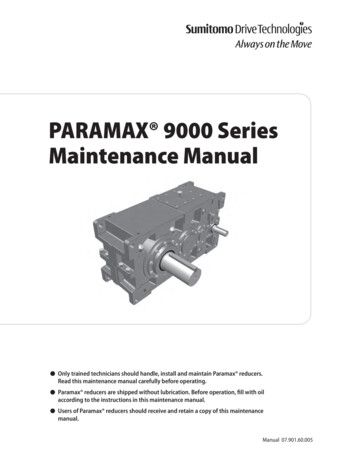
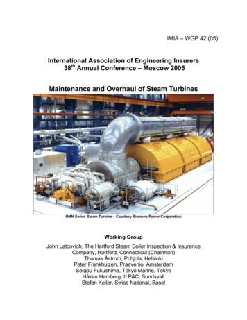
ENGLISH5.0 DESCRIPTION OF DANGER SIGNALS1) DangerousElectric voltage2) Air not fit forbreathing3) High pressure4) Fan rotating5) Hot parts6.0 DANGER ZONES6.1 DANGER ZONES(2)(1)(3)(4)Risks present on the whole machineFIG. 2BE6FIG. 213BE7 - BE10S11434 - Edition 07/2018 Cod. 9828093076 02 -2
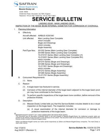
ENGLISH7.0 SAFETY DEVICES7.1 SAFETY DEVICES1) Cooling fan shield2) EarthFIG. 3BE621FIG. 3BE7 - BE10S21Cod. 9828093076 02 - Edition 07/2018 - 5
ENGLISH8.0 POSITION OF PLATES8.1 POSITION OF THE DANGER PLATES (Fig. 4)The plates fitted on the compressor unit are part of the machine; they have been applied for safety purposes and mustnot be removed or spoiled for any reason.Ref.1 - Spare plate Code 1079 9903 48FIG. 4BE61542311079 9903 48FIG. 4BE7 - BE10S1425311079 9903 488.2 POSITION OF THE DATA PLATES (Fig. 4)Ref. 2) “IN”Ref. 3) “OUT”Ref. 4) Identification plateRef. 5) Label for electrical equipment9.0 DRYERS ROOM9.1 FLOORThe floor must be even and of industrial type; the total weight of the machine is shown in Fig. 5Remember the total weight of the machine when positioning it.9.2 VENTILATIONThe choice of an appropriate room will prolong the life of your dryer; the room must be spacious, dry, well ventilated andfree from dust.The operating conditions to be complied with are the following:Min. room temperature: 41 F ( 5 C) (compulsory)Max. room temperature: 115 F ( 46 C) (compulsory)Max. temperature of incoming air: 131 F (55 C)Min. temperature of incoming air: 34 F ( 1 C)Max. working pressure: 203 psi (14 bar) Please keep environmental conditions stable (temperature and humidity) in order to avoid refrigerant compressor/fanoverload and/or reduction of dryer performance. Similar failures shall affect warranty reimbursements. Please ensure the appropriate composition of the air within the machine room: - clean with no damaging contaminants(e.g., dust, fibers, fine sand) - free of explosive or chemically unstable gases or vapors - free of acid/alkaline formingsubstances, particularly ammonia, chlorine or hydrogen sulfide. Similar failures shall affect warranty reimbursements. Please remember that we do not recommend the application of duct to extract air in presence of axial fans.6 - Edition 07/2018 Cod. 9828093076 02 -
ENGLISH10.0 TRANSPORT AND HANDLINGThe machine must be transported as shown in the following figures.TYPEQPNC-75 (BE6)QPNC-100 (BE7)QPNC-125 (BE7,5)QPNC-150 (BE9)QPNC-200 (BE10)QPNC-250 (BE10S)NET WEIGHTlb (Kg.)FIG. 597,0 (44)116,8 (53)132,3 (60)176,4 (80)176,4 (80)191,8 (87)11.0 UNPACKINGCUTTING THE METAL STRAPPING IS A DANGEROUS OPERATION, DO NOT ABANDON THE CUT PIECES IN THE ENVIRONMENT.After removing the packing, ensure that the machine is unbroken and that there are no visibly damaged parts.If you are in doubt, do not use the machine but apply to the manufacturer technical assistance service or to your dealer.The packing material (plastic bags, polystyrene foam, nails, screws, wood, metal strapping, etc.) must not be left withinthe reach of children or abandoned in the environment, as they are a potential source of danger and pollution.Dispose ofthese materials in the approved collection centres.12.0 INSTALLATION12.1 POSITIONINGAfter unpacking the equipment and preparing the dryers room, put the machine into position, checking the followingitems: ensure that there is sufficient space around the machine to allow maintenance (see Fig. 6).ENSURE THAT THE OPERATOR CAN SEE THE WHOLE MACHINE FROM THE CONTROL PANEL AND CHECK THE PRESENCE OF ANYUNAUTHORIZED PERSONS IN THE VICINITY OF THE MACHINE.FIG. 61ATTENTION:THE DISCONNECTOR SWITCH REF. 1 AND THEFUSES ARE NOT SUPPLIED WITH THE MACHINE.Minimum mt. 1,5 (59 in)12.2 ELECTRICAL CONNECTION Check that the supply voltage is the same as the value indicated on the machine data plate. Check the condition of the line leads and ensure that there is an efficient earth lead. Ensure that there are disconnector switch Ref. 1 Fig. 6 and fuses upstream the machine. For details (size andtype) see wiring/service diagram.ONLY PROFESSIONALLY SKILLED PERSONNEL MAY HAVE ACCESS TO THE ELECTRIC PANEL. SWITCH OFF THE POWER BEFOREOPENING THE DOOR OF THE ELECTRIC PANEL. COMPLIANCE WITH THE REGULATIONS IN FORCE CONCERNING ELECTRIC PLANTSIS FUNDAMENTAL FOR OPERATOR SAFETY AND FOR THE PROTECTION OF THE MACHINE.Cod. 9828093076 02 - Edition 07/2018 - 7
ENGLISH12.3 CONNECTION TO THE COMPRESSED AIR NETWORKFit a manual interception valve Ref. 1 between the machine and the compressed air network so that the dryer may beisolated during maintenance operations (see figure 7 ).Drainage of condensate Rif. 2 Fig. 7 (automatic) are led outside the machine with a flexible pipe that may be inspected.Drainage must comply with the local regulations in force. All refrigerant dryers shall be equipped with proper pre-filter at closest position to dryer air inlet (to be replacedaccording to service plan: once per year or even before in case of particular high humidity ambient conditions).ALL DAMAGE DUE TO THE FAILURE TO COMPLY WITH THESE NDICATIONS CANNOT BE ATTRIBUTED TO THE MANUFACTURER ANDMAY CAUSE INVALIDITY OF THE GUARANTEE CONDITIONS.12.4 STARTING UPSee part B of this manual, Chpter 18.0BE6FIG. 712BE7 - BE10S1FIG. 728 - Edition 07/2018 Cod. 9828093076 02 -
ENGLISH13.0 DIMENSIONS AND TECHNICAL DATABE7 - BE10SBE6LELECTRICAL CABLEELECTRICAL CABLE(A) AIR INLET(A) AIR INLETH(B) AIR OUTLET(B) AIR OUTLETTYPELQPNC-75 14,57 (370)QPNC-100 18,11 (460)QPNC-125 18,11 (460)QPNC-150 22,83 (580)QPNC-200 22,83 (580)QPNC-250 22,83 (580)TYPE97(44)TYPEWeightlb (Kg.)in (mm)W20,28 (515)22,64 (575)22,64 (575)23,82 (605)23,82 (605)23,82 (605)Refrigerant gas (1)QPNC-75R-134aQPNC-100-250R-410A(1) According to ISO 817(2) According to EN-378-1H30,08 (764)31,06 (789)31,06 (789)35,39 (899)35,39 (899)35,39 (899)Freon R134alb (Kg.)Weightlb (Kg.)QPNC-75CONDENSATEDRAININGCONDENSATEDRAININGWV 23060 HzV 11560 Hz0.66(0.30)0.66(0.30)V 4603Ph60 HzV 23060 HzV 11560 Hz0.85(635)0.93(694)V 11560 Hz2088V 4603Ph60 HzV 23060 HzV 11560 Hz0.076(57)0.076(57)V 23060 HzV 11560 HzV 4603Ph60 HzV 23060 HzV 11560 Hz0.93(692)1.01(751)V 23060 HzV 11560 HzV 4603Ph60 HzB1” GAS F.1”1/2 GAS F.1”1/2 GAS F.1”1/2 GAS F.1”1/2 GAS F.1”1/2 GAS F.psi (bar)MAX.V 4603Ph60 Hz203(14)psi (bar)MAX.NominalPower hp (W)NominalPowerhp (W)V 4603Ph60 HzA1” GAS F.1”1/2 GAS F.1”1/2 GAS F.1”1/2 GAS F.1”1/2 GAS F.1”1/2 GAS F.NominalPower hp (W)NominalPowerhp (W)NominalPowerhp (W)V 4603Ph60 2501430NominalPowerhp (W)Freon R410Alb (Kg.)V 23060 HzGWP 100 (2)V 23060 HzV 11560 HzV 4603Ph60 C-250191,8(87)2,315(1,050)Reference conditions:Ambient temperature 100 F ( 38 C)Inlet air temperature 100 F ( 38 C)Working pressure 100 psi (7 bar)Dew point in pressure 39 F ( 4 C)2,855(2129)0,389(290)3,244(2419)Limit conditions:Max. ambient temperature 115 F ( 46 C)Min. ambient temperature 34 F ( 1 C)Max. inlet air temperature 131 F ( 55 C)Max. working pressure 203 psi (14 bar)Cod. 9828093076 02 - Edition 07/2018 - 9203(14)
ENGLISH14.0 MACHINE ILLUSTRATION14.1 GENERAL LAY-OUTBE6FIG. 88643752112345678BE7 - BE10S643527110 - Edition 07/2018 Cod. 9828093076 02 -8Refrigerant compressorCondenserMotor fanEvaporatorCondensate drainHot gas by-pass valveRefrigerant filterExpansion capillary tube
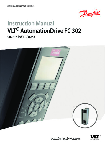
ENGLISH14.2 COMMAND AND CONTROL PANELBEFORE CARRYING OUT THE OPERATION TEST, READ CAREFULLY AND ACQUIRE A GOOD KNOWLEDGE OF THE COMMANDFUNCTIONS.12345FIG. 99711126108Reference123456789108 98 101112NameAlarm iconRefrigerant compressor iconFan iconPDP (dewpoint) temperatureUnit ( C or F)Alarm LEDButton to snooze or to reset the alarmSET buttonUP buttonDOWN buttonBack to previous screenMenuDigital essorMODEOFFONONONOFFONFlashing SEFlashing L2Flashing CountdownFlashing H3FanOFFFlashingONFUNCTIONSNo active alarmsProbe failure alarmHigh/Low temperature alarmService alarmDryer offDryer onMaintenance warningDewpoint too low / Dryer is stoppedResidual time before startToo high discarge temperature of the refrigerant compressor(see “H3” pag. 12) Dryer is stoppedFan offNot applicableFan onSTARTING DRYERS (ONLY FOR BE7 - BE10S)Flashing: countdown before starting the refrigerant compressor for internal pressure balancing (180 seconds).Cod. 9828093076 02 - Edition 07/2018 - 11
ENGLISHREMOTE ALARM FUNCTIONThe controller allows to remotely control a number of alarms. This is managed by means of a free NC (Normally Closed)contact.The contact opens in case of an alarm or when the dryer is switched off.Refer to the table below to identify the availability of the function and refer to the related picture Fig. 9a Ref. 1 to identifythe physical location of the free contact connector.Is possible remote alarm for P1, P2, P3, L2, H2 and H3. For the details of alarm see Cap. 17.1 Pag. 12.FIG. 9aLocation of the free contact connector (1)15.0 SCRAPPING THE UNITIf the machine is to be scrapped, it must be dismantled into parts of the same material, to be disposed of according to thelocal regulations in force.ALWAYS RESPECT THE REGULATIONS IN FORCE FOR DISPOSING OF OLD OIL AND OTHER POLLUTING MATERIALS SUCH ASINSULATING FOAM, ETC.12 - Edition 07/2018 Cod. 9828093076 02 -
ENGLISHPART “B”THIS PART “B” OF THE INSTRUCTIONS MANUAL IS RESERVED FORPROFESSIONALLY SKILLED PERSONNEL APPROVED THE MANUFACTURER.16.0 PARTIAL ROUTINE MAINTENANCEBEFORE CARRYING OUT ANY MAINTENANCE JOBS IT IS OBLIGATORY TO STOP THE MACHINE AND DISCONNECT IT FROM THEPOWER MAINS AND FROM THE COMPRESSED AIR DISTRIBUTION NETWORK.16.1 MAINTENANCE SCHEDULEThese maintenance intervals are recommended for work environments that are not dusty and are will ventilated. Forparticularly dusty environments, double the frequency of controls.Every weekBrush/blow off the finned surface of the condenserClean the filter of the automatic condensate drainReplace the filter of automatic condensate drain (2902016102)Replace drain kit (2200902017) Every 2000 hours / 1 yearEvery 4000 hours / 2 year16.2 CLEANING OF THE AUTOMATIC CONDENSWATER DISCARGER FILTER (Fig. 10)Clean the filter of the steam trap.Proceed as follows:- Close the valve Ref. 1 Fig. 10- Release the pressure in the dryer by pressing the condensate drain “TEST” pushbutton locate on the steam trapRef. 2 Fig. 10.- Turn the switch in “OFF” position Ref. 3 Fig. 10- Turn off the supply (see disconnector switch Ref. 4 Fig. 10)HOT PARTS INSIDE- Remove the panels Ref. 5- Remove the stopper Ref. 6- Remove the filter Ref. 7- Clean the filter Ref. 5 with a jet of air, working from inside to outside- Install the filter, fix the plug Ref. 7 - 6- Close the panels Ref. 5FIG. 104BE7 - BE10S2356751BE65Cod. 9828093076 02 - Edition 07/2018 - 13
ENGLISH16.3 CLEANING THE CONDENSER (Fig. 10)The condenser must be cleaned every month.Proceed as follows:- Turn the switch in “OFF” position Ref. 3 Fig. 10- Turn off the supply (see disconnector switch Ref. 4 Fig. 10)- Remove the panels Ref. 5 Fig. 10- Clean the condenser fins Ref. 1 with compressed air (Fig. 10) DO NOT USE WATER OR SOLVENTS- Close the panels Ref. 5 Fig. 1017.0 TROUBLE-SHOOTING AND EMERGENCY REMEDIESALL WORK MUST BE CARRIED OUT BY PROFESSIONALLY SKILLED PERSONNEL. BEFORE CARRYING OUT ANY MAINTENANCEJOBS IT IS OBLIGATORY TO STOP THE MACHINE AND DISCONNECT IT FROM THE POWER MAINS.N.B. OPERATIONS MARKED MUST BE CARRIED OUT BY PROFESSIONALLY SKILLED PERSONNEL APPROVED THEMANUFACTURERFAULT FOUNDPOSSIBLE CAUSES1) No compressed air passes through the dryeroutlet1A) The pipes are frozen inside2) Presence of condensate in the pipings.2A) The condensate separator does not workcorrectly2B) The dryer is working outside its ratingOBSERVATIONS -The bypass valve of the hot gas is broken orout-of-calibration-The room temperature is too low and theevaporators piping are obstructed with ice-Clean the filter from the condensate drain -Check the condensate drain-Check the flow rate of treated air-Check the room temperature-Check the air temperature at the drier inlet.-Clean the condenser.3) The compressor head is very hot.4) Motor cuts out on overload5) The motor hums and does not start.6) The machine (compressor) has stopped and doesnot restart even after a few minutes.7) The compressor is very noisy.2C) The dryer is working under bad conditions for aircooled condenserSee 2B aboveSee 2C above3A) The cooling circuit is not working with the rightgas chargeSee 2B aboveSee 2C aboveSee 3A aboveThe line voltage is too low.The starting system of the motor is defective.The overload protection has tripped: makereference to 2B-2C-3A.The motor is burned.Troubles with the internal mechanical parts orwith the valves14 - Edition 07/2018 Cod. 9828093076 02 - -Check the good operation of the fan. - See allarm “H3” pag. 12 -Check if there are leaks of refrigerating gas. - Charge it again.-Contact the electric power company -Check the running capacitor
ENGLISH17.1 DIGITAL CONTROL ALARMSN.B. OPERATIONS MARKED MUST BE CARRIED OUT BY PROFESSIONALLY SKILLED PERSONNEL APPROVED THEMANUFACTURERDisplayFlashing fault messageDescriptionPossible root causesDryer is working OKn/aWarning icon NOTflashing, label P1 flashingFan control probe failed replace probeWarning icon NOTflashing, label P2 flashingPDP Temp probe failed replace probeWarning icon NOTRefrigerant compressorflashing, label P3 flashing temperature probe failedObservations replace probeHigh PDP refrigerant leak flow rate / inlet temperatureexeeding the limit. call for serviceWarning icon NOTflashing, label L2 flashingLow PDP hot gas by passvalve out of order. ambient temperaturelower then limits call for serviceWarning icon NOTflashing, label H3flashingHigh refrigerantcompressor temperatureWarning icon NOTflashing, label H1flashingHigh temperaturedischarge condenser check probe call for serviceWarning icon NOTflashing, label L1 flashingLow temperaturedischarge condenser check probe call for serviceWarning icon NOTflashing, label H2flashing refrigerant leak call for serviceCod. 9828093076 02 - Edition 07/2018 - 15
ENGLISH“EE” ALARMEE alarm is shown when internal EPROM errors happens, if this warning will appear, the dryer will stop running. The error can be reset by pressingone of the four buttons of the controller, anyway please replace the controller itself.NOTE: In case of EE alarm please contact your tech support.“SE” ALARMAfter 6000Hrs, the controller will issue a “SE” warning. This is the maintenance due warning.FREEZE PROTECTION FUNCTIONOnce the digital controller detects a dewpoint temperature below -35,6 F (-2 C) during more than 2 minutes (L2 Alarm),it switches off the refrigerant compressor.AUTOMATIC CUT OUT OF REFRIGERANT COMPRESSORIf the refrigerant temperature detected at the delivery pipe of refrigerant compressor overcome the limit setted bymanufacturer, the controller stops the refrigerant compressor in order to avoid further possible failure.COMPRESSOR RE-START AFTER A STOPIf freezing or superheating alarm occurs,the controller stops the compressor and the re-start has to be manualyactivated.Before re-starting the dryer it is necessary to identify the root cause; such alarms indicate possible failure it is necessaryto call customer center. Restart the dryer without a deep investigation on possible root cause will affect the reliability ofthe dryer and overrule the warranty reimborsment.Press button Ref. 7 Fig. 9 to reset the alarm.The dryer restarts when both the following conditions are satisfied: The dewpoint temperature is higher than -35,6 F (-2 C).Only for BE7 - BE10S 180 seconds are elapsed from the refrigerant compressor stop (minimum balancing pressure stop time).A countdown is available if the reset is made before the minimum stop time.SILENT ALARM FUNCTIONTo snooze the alarm, press button Ref. 7 (See Fig. 9)16 - Edition 07/2018 Cod. 9828093076 02 -
ENGLISHHow to reset the maintenance warning: follow steps 1 to 12UP1SETDOWN2Push and hold buttons “SET” and“DOWN” to enter in the menu.PDP is flashing between standard viewand “SE” alarm4356Message “rS” appears on display.Push and release button “UP”.78Message “n” appears on display.10Push and release button “SET”.9Message “y” appears on display.Push and release button “UP”.11Push and release “SET” to resetservice alarm.Message “SE” appears on display.12Message “y” blinks for 3 seconds.Then “rL” is fixed and “ C” blinks ondisplay for 10 seconds.Service alarm is resetCod. 9828093076 02 - Edition 07/2018 - 17
ENGLISHPROCEDURE TO SET THE SERVICE INTERVAL ON PDP DEVICEUP1SETDOWN2Push and hold buttons “SET” and“DOWN” to enter in the menu.PDP is showing standard view.4356Current service interal is displayed.Push and release “SET” to enter in the“SE” menu.7Select desired service interval using“UP” or “DOWN”.(“60” or different value from “0” to“99”)8Push and release “SET” to configurenew service interval.Message “SE” appears on display.(40 4000h, 55 5500h, 80 8000h, )9Value selected blinks for 3 seconds.Then “rS” is fixed and “ C” blinks ondisplay for 10 seconds.New service interval is set18 - Edition 07/2018 Cod. 9828093076 02 -
ENGLISH18.0 STARTING UPBEFORE CARRYING OUT ANYOPERATION ON THE MACHINE, ENSURE THAT THE ELECTRIC POWER SUPPLY HAS BEENDISCONNECTED18.1 PRELIMINARY CONTROLSBefore starting the dryer, check:- The correct connection to the compressed air piping: remember to remove eventual caps on the drier inlet and outlet.- The correct connection to the condensate drainage system.- That the power supply is right.18.2 STARTING AND STOPStart the system before the air compressor starts running and stop it after the air compressor has been stopped. Thecompressed air piping will be free of condensate only by doing so. The drier must be kept running during all the time theair compressor is running. WARNING: if the drier is switched off, before starting it again, wait at least 5 minutes in orderto allow the pressure balancing.BEFORE CARRYING OUT ANY MAINTENANCE JOBS IT IS OBLIGATORY TO STOP THE MACHINE AND DISCONNECT IT FROM THEPOWER MAINS AND FROM THE COMPRESSED AIR DISTRIBUTION NETWORK.PRESSURE DISCHARGE PROCEDUREProceed as follows:- Close the valve Ref. 1 Fig. 11- Release the pressure in the dryer by pressing the condensate drain “TEST” pushbutton locate on the steam trapRef. 2 Fig. 11- Turn the switch in “OFF” position Ref. 3 Fig. 11- Turn off the supply (see disconnector switch Ref. 4 Fig. 11)FIG. 114BE7 - BE10S2356751BE65Cod. 9828093076 02 - Edition 07/2018 - 19
ENGLISHCALIBRATIONSBYPASS VALVE FOR HOT GASN.B.These valves have already been calibrated and they do not require any adjistment. A dew point different from therated one generally depends on causes which are not attributable to their operation.Ref. 1) Closing capRef. 2) Adiusting screwWORKING PRESSURES AND TEMPERATURES OF R410ASUCTION SIDE OFREFRIGERATION COMPRESSOREvaporat.Temperat. F ( C)RATED VALUES(Temperat.68 F - 20 C)EvaporatingPressure psi (bar)33,8 35,6(1 2)R410A105,6 109,5(7,28 7,55)1WORKING PRESSURES AND TEMPERATURES OF R134a2SUCTION SIDE OFREFRIGERATION COMPRESSOREvaporat.Temperat. F ( C)RATED VALUES(Temperat.68 F - 20 C)33,8 35,6(1 2)EvaporatingPressure psi (barg)R134a29,3 30,9(2,02 2,13)20 - Edition 07/2018 Cod. 9828093076 02 -
INSTRUCTION AND MAINTENANCE MANUAL DRYERS QPNC-75 (BE6) - QPNC-100 (BE7)- QPNC-125 (BE7,5) - . In particular the appliance cannot be used to produce air to be breathed by humans or used on direct contact with . according to service plan: once per year or even before in case of particular high humidity ambient conditions). .