Transcription
PARAMAX 9000 SeriesMaintenance ManualOnly trained technicians should handle, install and maintain Paramax reducers.Read this maintenance manual carefully before operating.Paramax reducers are shipped without lubrication. Before operation, fill with oilaccording to the instructions in this maintenance manual.Users of Paramax reducers should receive and retain a copy of this maintenancemanual.Manual 07.901.60.005
Table of ContentsSafety Precautions . 1Inspection and Storage . 2Transport. 3Nomenclature . 4Standard Speed. 5Installation . 6Connecting to Machinery . 8Operation.11Lubrication .12Daily Inspection .18Construction Drawings.19Parts Maintenance .25Disassembly / Assembly.25Troubleshooting.26AddendumsDetermining Proper Oil Level .28Taconite and Labyrinth Seal Lubrication .29Drywell and Drop Bearing Grease Procedure.30Assembly - Monobloc Style Housing.31Assembly - Internal Type Backstops.34Safety PrecautionsCarefully read this maintenance manual and all accompanying documents before use (installation, operation,maintenance, inspection, etc). Thoroughly understand the machine, information about safety, and all precautions forcorrect operation. Retain this manual for future reference.Pay close attention to the "DANGER" and "CAUTION" warnings regarding safety and proper use.! DANGER: Improper handling may result in physical damage, serious personal injury and/or death.! CAUTION: Improper handling may result in physical damage and/or personal injury.! CAUTIONItems described inwarnings described within.may lead to serious danger depending on the situation. Be sure to observe important!DANGERTransport, installation, plumbing, operation, maintenance, and inspections must be performed by properly trainedtechnicians ; otherwise, injury or damage to the machine may resultWhen the unit is to be used in a system for transport of human beings, a secondary safety device should be installed toguard against accidents that may result in injury, death, or damage to the system.When the unit is to be used for an elevator, install a safety device on the elevator side to prevent it from falling; otherwise,serious injury, death, or damage to the elevator may result.!CAUTIONOperate the unit only within its design and performance specifications ; otherwise, injury or damage to the system may occur.Keep hands and all foreign objects from the internal moving parts of the unit; otherwise, injury or damage to the systemmay occur.Take damaged units off-line immediately and do not resume operation until properly repaired.Modifications or alterations of any kind to the unit will void the warranty and all subsequent claims.Do not remove the rating plate.Paramax reducers are shipped without oil. Before operation, fill with oil according to the instructions in the Lubrication sectionof this manual.Paramax 9000 Series1
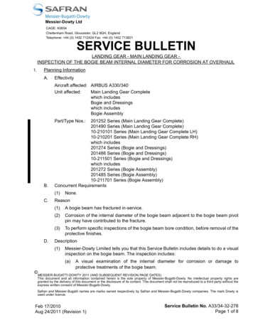
Paramax 9000 Speed ReducersInspection and StorageInspection Upon Delivery! CAUTIONIn order to avoid injury, verify that the reducer is positioned right-side up before unpacking. Some units are not shipped right-side up, sore-positioning may be required.Verify that the reducer received matches your order. Installing an incorrect product is may result in personal injury or damage to the system.Do not remove rating plate.Upon delivery of the Paramax reducer, verify that:(1) The descriptions on the rating plate match your order.(2) There were no parts damaged during transport.(3) All bolts and nuts are firmly tightened.If there is any doubt that the unit delivered does not match your order, contact the nearest Sumitomo agent, distributor or serviceoffice.Rating Plate InformationRSpeed Reducer ModelBEREMFMOMODELSerial NumberSERIAL NO.Input PowerAGMA LUB.INPUT HP/KWOUTPUTSPEEDINPUT RPMReduction RatioRPM 100RPM 100MECH RATINGRATIO:AMB. TEMP. F14/5932/8650/122 C -10/150/3010/502 EP3 EP4 EP5 EP5 EP6 EPCHANGE OIL EVERY 6 MO. OR2500 HRS WHICHEVER OCCURSFIRST. USE INDUSTRIAL TYPEPETROLEUM BASED (EP) GEAR OIL.DATESUMITOMOMACHINERYCORP. OF AMERICACHESAPEAKE, VIRGINIAPMPA7510Fig.1 Paramax Reducer Rating plate Have theMODEL,SERIAL NO., andRATIO information ready when making inquiries.StorageDo not store the Paramax reducer longer than six months, unless long-term storage was specified when the order was placed.Follow the instructions outlined below when storing the reducer for an extended period of time before installation.Storage LocationStore the reducer indoors in a clean, dry area that is relatively free of humidity, dust, extreme temperature fluctuation or corrosive gas.Do not store outdoors or in a wet location.Storage PeriodUp to Six Months:(1) Fill the reducer with the recommended lubricant (see Lubrication section in this manual).(2)Every two or three months, hand rotate the shaft for the number of turns that is equivalent to the reducer’s ratio. Forexample, if the ratio is 35, rotate the shaft 35 complete turns.Six Months - One Year (When Specified at Time of Order):(1) Special rust-proofing is applied at the factory before shipping. The rust preventative NP-20 (Shell VSI Circulating Oil#32 or equivalent) is sprayed into the reducer and the air vent is replaced with a red sealing plug.(2) Do not operate the reducer with the rust preventative oil. Drain the rust preventative and fill with the recommendedlubricant before operating.2Paramax 9000 Series
Paramax 9000 Speed ReducersStorage (cont.), TransportStorage Period (cont.)More Than One Year (When Specified at Time of Order):(1) Before shipping from the factory, the rust preventative NP-20 (Shell VSI Circulating Oil #32 or equivalent) is sprayedinto the reducer and the air vent is replaced with a red sealing plug.(2) After the first year of storage, add the correct amount of rust preventative NP-20 (Shell VSI Circulating Oil #32 orequivalent) into the reducer (see Table 1).(3) Hand rotate the shaft for the number of turns that is equivalent to the reducer’s ratio. For example, if the ratio is 35,rotate the shaft 35 complete turns.(4) Wipe seal face with approved grease (refer to lubrication section for grease recommendations) to help protect againstdry rot.(5) Replace the plug in the air vent. Repeat steps 2-4 for every year of storage.(6) Do not operate the reducer with the rust preventative oil. Drain the rust preventative and fill with the recommendedlubricant before operating.Table 1. Rust Preventative Quantity- Shell VSI Circulating Oil #32 or equivalentReducer SizeQuantitygal.9015 - 90359040 -90559060 -90759080 - 90959100 - 91189121 - 91360.10.150.250.512Operation After Storage(1) Oil seals deteriorate when exposed to high temperatures and UV rays. Inspect the oil seals before operating theParamax reducer.(2) After starting the reducer, verify that there is no abnormal sound, vibration, or heat rise. Contact our nearest agent,distributor, or sales office if you observe any abnormality.Transport! DANGERDo not stand directly under a unit suspended by a crane or other lifting mechanism; otherwise, injury or death may result.CAUTION! CExercise ample care so as not to drop the reducer. If a hanging bolt or hole is provided, be sure to use it.After mounting a Paramax reducer to the equipment, do not hoist the entire machine using the hanging bolt or hole;otherwise, personal injury or damage to the equipment and/or lifting device may result.Before hoisting, refer to the rating plate, crate, outline drawing, catalog, etc. for the weight of the Paramax driveor reducer. Never hoist a unit that exceeds the rating of the crane of other mechanism being used to lift it;otherwise, personal injury or damage to the equipment and/or lifting device may result.Paramax 9000 Series3
Paramax 9000 Speed ReducersNomenclatureStandard ModelPPARAMAXPPHD9075R3YRLKF35.5Nominal ReductionRatioAuxiliary TypeRef. to Table 6Auxiliary TypeNumber ofGear StagesRef. to Table 5Ref. to Table 10Slow-Speed ShaftTypeRef. to Table 9AssemblyRef. to Table 4Slow-Speed ShaftArrangementRef. to Table 7Frame SizeHigh-Speed ShaftTypeRef. to Table 8Housing TypeRef. to Table 3High-Speed ShaftArrangementRef. to Table 7Mounting MethodRef. to Table 2Table 2Table 6Mounting methodHVWRFTHorizontalVerticalUprightUpright Flipped OverHorizontal/Upside DownVertical/Upside DownTable 3Housing typeADBMono-block housingSplit housingSpecial split housingYAYAFYFWRJUDLHParallel shaftsRight-angle shaftsSpecial right angleTable 5Number of Gear Stages4High-Speed ShaftBlankMYJRLBDSolid shaftHollow Input with Motor(Right Angle Only)Hollow input shaft with flange(right angle shaft only)With high speed adapterTable 9Slow-Speed ShaftBlankKTSolid shaftHollow output shaft key typeHollow output shaft shrink disc typeTable 10Auxiliary TypePosition of Projected High/Slow-Speed Shaft*Assembly234Inch shaftSteel fabricated housingSteel fabricated housing Inch shaftDuctile iron housingDuctile iron housing Inch shaftWall mountHeavy duty LS bearingReverse wall mountCeiling mountLS drop bearingHD LS drop bearingThrust bearingTable 7Table 4PRZTable 8Auxiliary typeRight side viewed from high-speed shaftLeft side viewed from high-speed shaftBoth sidesBoth sides (Reverse gear arrangement of B's)*Projected high-speed shaft of right angle shaftis depended on the position of Bevel gear.FGBFBEC1 Radial fan1 Radial fan (opposite side)Backstop1 Radial fan BackstopImmersion Oil HeaterCooling CoilDouble reductionTriple reductionQuadruple reductionParamax 9000 Series
Paramax 9000 Speed ReducersStandard SpeedInput SpeedThis manual shows the standard lubrication system when the input speed is within the standard input speed range (Refer to Table 11).When the input speed exceeds the standard input speed range, consult factory after checking the operating condition in detail. Thelubrication system is determined according to the operating condition.GearboxThis manual is applied to the standard gearbox. Lubrication system for specially designed gearboxes may be completely different fromthe standard lubrication system. Consult the factory for the lubrication system of upright mounted gearboxes (W).Table 11. Standard Speed TableParallel ShaftShaft Number of Gearbox SizePosition Gear tionRight Angle ShaftHorizontal rupleReductionParallel ShaftTripleReductionQuadrupleReductionRight Angle ShaftVertical ionQuadrupleReduction9015 90559060 90859090 , 90959100 , 91059110 , 91159015 90559060 90859090 91159030 90559060 90859090 91159015 90559060 90759080 , 908590959105 , 91159030 90559060 90859090 , 90959100 9115Lubrication100015001800Splash LubricationOilbathSplash LubricationOilbathSplash LubricationOilbathSplash LubricationForced Lubrication(Electric Pump)OilbathSplash LubricationOilbath9015 9085Forced Lubrication(Shaft Driven Pump)9090 , 90959100 , 91059110 , 9115Forced Lubrication(Electric Pump)9015 9085Forced Lubrication(Shaft Driven Pump)9090 9115Forced Lubrication(Electric Pump)9030 9105Forced Lubrication(Shaft Driven Pump)9110 , 9115Forced Lubrication(Electric Pump)9015 90559060 90759080 , 90859030 90859090 , 9095Forced Lubrication(Shaft Driven Pump)9040 9115500Oilbath9040 91159100 9115Input Speed (r/min)200(Note 4)(Note 4)Forced Lubrication(Electric Pump)Forced Lubrication(Shaft Driven Pump)Notes: 1. Standard input speed range is indicated by unshaded cells.2. Consult factory for non-standard lubrication or input speed indicated by shaded cells.3. Lubrication may be changed when heat capacity, noise level, etc. are not within limits of this table.4. Depending on the reduction ratio and rotation speed, external piping may be necessary. Consult factory for details.Paramax 9000 Series5
Paramax 9000 Speed ReducersInstallation! DANGERDo not operate a standard unit in an explosive atmosphere; electric shock, personal injury, explosion, fire or damage to theto the equipment may occur.Install inverters in a location free from explosive gas; electric shock, personal injury, explosion, fire or damage to theequipment may occur.! CAUTIONDo not use the Paramax reducer for applications other than those shown on the rating plate. Electric shock, personalinjury or damage to the equipment may occur.Do not place flammable objects around the reducer; fire may occur.Do not place any object around the reducer that will hinder ventilation. Insufficient ventilation can cause excessiveheat build-up that may cause burns or fire.Do not step on or hang from the reducer; injury may occur.Do not touch the shaft, inside the keyway or edge of the motor cooling fan with bare hands; injury may occur.When the reducer is used in a food processing application, install an oil pan to protect against oil contamination thatmay occur during equipment breakdown or failure.Installation LocationAmbient Temperature:Ambient Humidity:Altitude:Ambient Atmosphere:Location:14 F to 104 F (-10 C to 40 C)85% maximum3280 ft. maximum (1000 m )The atmosphere should be free of corrosive gas, explosive gas or steam; well ventilated and dust free.Indoors, clean and dry.Special reducers are required for installation conditions not described in these guidelines.Protect gearbox from exposure to direct sunlight.Reducers made for outdoor, explosion-proof or other special conditions are designed to operate under thoseconditions without any problem.Install reducers where inspection, maintenance and repair operations can be performed easily.Install reducers on a sufficiently rigid base.Installation AngleInstall the Paramax reducer on a level base. (Contact Sumitomo for installation on an inclined base).When the unit is manufactured for inclined installation, do not install it at any angle other than the one specified.For a standard reducer, the installation angle must be within the limits shown in Fig. 2.Use installation bolts corresponding to JIS/ISO/ASTM strength class 10.9 or its equivalent.1 0Paramax 9000 Series0.3 Fig. 2 Installation Angle Limits6Paramax 9000 Series
Paramax 9000 Speed ReducersInstallation (cont.)Installation Procedure - Reducer with Fan (Parallel Shaft)! CAUTIONAvoid contact with sharp edges of keyways and other parts.During installation, keep small parts, such as screws, in a container so as not to lose them.Handle parts carefully to prevent damage. Avoid contact with water and dust.Follow these steps to install the reducer:(1) Remove bolts 1 and 2 and then remove the fan hood 3 (Fig. 3). (2) Install the reducer on the mounting surface using bolt 9 (Fig. 6).If there is not enough space to tighten bolt 9,(Fig. 6) then:If the fan rotor 7 (Fig. 5) and fan hood 5 (Fig. 4) are removed, then:(a) Remove bolt 4 and then fan hood 5 (Fig. 4).(a) Install fan rotor 7 to the fan hub 8 with bolt 6 (Fig. 5).(b) Remove bolt 6 and then fan rotor 7 (Fig. 5).(b) Install fan hood 5 to the reducer with bolt 4 (Fig. 4).(3) Install fan hood 3 to the reducer with bolts1 and 2 (Fig. 3).Refer to Table 16 for tightening torques of bolts 1, 2, 4 and 6.Fig. 3Fig. 4Bolt 1Bolt 2Fan hood 5Fan hood 3Bolt 4Fig. 6Fig. 5Bolt 6Fan rotor 7Fan hub 8Bolt 9Table 12. Bolt TorqueBoltTorquein lbf (Nm)Bolt 1, 2, 4Bolt 6M6BoltTorquein lbf (Nm)Bolt 1, 2, 4Bolt 695.6 (10.8)M201682 (190)—M8100 (11.3)—M242903 (328)—M10347 (39.2)—M305770 (652)—M12862 (97.4)—M3610090 (1140)—Torque tolerance: 10%Paramax 9000 Series7
Paramax 9000 Speed ReducersConnecting to MachineryC! CAUTIONWhen connecting the Paramax reducer to a load, confirm that the alignment is within the specified limits shown in themaintenance manual, drawings, catalog, etc. otherwise, damage to the system may occur due to misalignment.Correctly tighten all bolts to the torque specified in the drawing, catalog, etc. to prevent system damage from loose parts.When a belt is used to connect the reducer with other equipment, check that the belt tension and the pulley alignment arewithin the specified limits. When the unit is directly connected to other machinery, check that the alignment is within thespecified limits; otherwise, the system may be damaged from misalignment.Remove the key temporarily attached to the output shaft of the Paramax reducer when the shaft is free-rotating(i.e. not loaded); otherwise injury may occur.Confirm the direction of rotation before connecting the Paramax reducer with its driven machine.Incorrect direction of rotation may cause injury or damage to the system.Install appropriate guard devices around rotating parts; otherwise, injury may occur.Coupling(1) CouplingFollow Manufacturers installation recommendations when installing shaft connections toSumitomo equipment. The following information is supplied for reference only. Manufacturersinstallation instructions supersedes any information supplied below.The dimensions (A,B and X) illustrated in Fig. 8 must be within the tolerance listed in Table 13.When attaching a coupling, do not to apply impact force or excessive thrust to the shaft;otherwise, the bearing may be damaged.Shrink fit or shaft-end thread is recommended for mounting (Fig. 8).ShaftShaft-End ThreadFig. 7BTable 13. Coupling Alignment ToleranceTolerance for A dimensionAXX0.002 in. (0.05mm)Tolerance for B dimension0.002 in. (0.05mm)Tolerance forX dimensionSpecified by couplingmanufacturerFig. 8(2) Chain, Sprocket and GearThe chain tension angle must be perpendicular to the shaft of Paramax reducer.The pitch circle of the sprocket and gear must be more than three times of the shaft diameter.Position the sprocket and gear as close to Paramax reducer as possible so the load point will be close to the reducer’svertical centerline (Fig. 9).(3) V beltExcessive V belt tension will damage the output shaft and bearing. The amount must be specified by V belt manufacturer.Eccentricity of parallelism between two pulleys must be less than 0.5º (Fig. 10).Use a matched set with identical circumferential length when more than one V belt is used.CouplingParamax ReducerShaftFig. 98Fig. 10Paramax 9000 Series
Paramax 9000 Speed ReducersConnecting to Machinery (cont.)Hollow ShaftShrink Disk TypeThe shrink disc has a keyless, shrink fit mechanism that shrinksthe hub (HB) mechanically through the tightening lockingbolt (ZS),and holds shaft and hub as one fixture (Fig. 11).Mounting Procedure: (Fig. 12)(1) Clean and degrease contact surfaces (a) and (c).(2) Smear surface (c) and (ZS) with "Molykote 321" or itsequivalent. However, keep surface (a) as clean as possible(no grease).(3) Slide O-ring (b) onto the shaft. (only 9090 - 9115)(4) Mount the reducer on the driven shaft and screw nut (e)until faces (g) and (h) make contact.(5) Set the shrink disc (k) at dimensions (LV). Tighten lockingbolt (ZS) to specified torque (TA) (using a torque wrench).Make sure that both plates are parallel when tighteningbolts. After confirming that the shrink disc is set correctly,tighten the bolts with a wrench of appropriate length.Uniformly, tighten bolts clockwise (not diagonally) whilekeeping both plates parallel. It is recommended to tightenrespective bolts by 30 degree each time.Notes: a. In case of a vertical type unit, mount a thrust washer(B) to prevent the reducer from moving when lockingnut (ZS) is loosened (Fig. 11).b. A high-tension bolt (JIS/ISO/ASTM strength 10.9 or12.9) is used as a locking bolt (ZS). When replacing it,use one specified by the manufacturer.Removal Procedure: (Fig. 13)(1) Loosen locking bolt (ZS) and remove shrink disc (k).(2) Set thrust washer (f) and hexagon head bolt (n). Removethe reducer from the driven shaft using bolt (m).Note: Parts (d), (e), (f ), (ZY), (m), and (n) are optional. Orderthese as required.(HB)(B)(ZS)(HB)(B)(ZS)Fig. 11 Full Mounted Position( c)( b)( a)( g)( h)( c)( b)( g)( h)(LV)( ZY )( d)( e)( f)(ZS)(K)( a)(LV)( ZY )(K)( d)( e)( f)(ZS)Fig.12 Mounting(ZY)(n)(f) (m)Fig. 13 RemovalParamax 9000 Series9
Paramax 9000 Speed ReducersConnecting to Machinery (cont.)Hollow Shaft (cont.)( d)( c)( b)( a)( e)Keyway ConnectionSizes 9015 - 9055Mounting Procedure: (Fig. 14)The hollow shaft bore is provided with retaining ring (d). Ring (d) is theessential component for mounting, securing, and removing the unit.(1) Smear surface of the shaft (e) with "molykote 321" or itsequivalent.(2) Turn nut (b) and slide the reducer over the driven shaft.Use plain washer (c) if necessary.Fig. 14( f)( g)Fig. 15Securing: (Fig. 15)(1) After mounting the reducer on the driven shaft, tighten bolt (f).Bolt (f) is not supplied with the unit.(2) Install cover (g) to protect the bore.( d)Removal Procedure: (Fig. 16)(1) Remove ring (d), mount bolt (n), and reset ring (d).(2) Attach bolt (J) to ring (d), and turn bolt (J) to disconnect thehollow shaft from the driven shaft.Fig. 16( n)( f)Special Cases: (Fig. 17)If the driven shaft has no shoulder when mounting, provide a distance ring (h) for fixing in place. Ring (h) is not supplied with the unit.Sizes 9060 - 9085Mounting Procedure: (Fig. 18)The hollow shaft end is provided with thrust washer (d). Thrust washer(d) is the essential component for mounting, securing, and removingthe unit.(1) Smear surface of the shaft (e) with "molykote 321" or itsequivalent.(2) Turn nut (b) and slide the reducer over the driven shaft.( g)Fig. 17( h)( d)( e)( b)( a)Fig. 18Securing: (Fig. 19)(1) After mounting the reducer on the driven shaft, fix bolt (f). Bolt(f) is not supplied with the unit.(2) Install cover (g) to protect the bore.Removal Procedure: (Fig. 20)(1) Remove thrust washer (d), mount bolt (n), and reset thrustwasher (d).(2) Attach bolt (J) to thrust washer (d), and turn bolt (J) to disconnectthe hollow shaft from the driven shaft.Special Cases: (Fig. 21)If the driven shaft has no shoulder when mounting, provide adistance ring (h) for fixing in place. Ring (h)is not supplied with theunit.( J)( f)( g)Fig. 19( J)Fig. 20( n)Note: Parts (a), (b), (c), (n), and (J) are optional. Order these as required.( f)( g)Fig. 2110( h)Paramax 9000 Series
Paramax 9000 Speed ReducersConnecting to Machinery (cont.), OperationHollow Shaft (cont.)M2Torque Arm (optional)M1ReducerThe hollow shaft reducer is fixed by the torque arm to prevent the reducer fromrevolving by an opposite reaction force. Fig. 22 shows the construction of a standardtorque arm. Select a torque arm support with proper construction and strength,staking into con- sideration the reaction force of the reducer and the impact load.Notes: a. The number of disc springs (s) differs according to the size of thetreducer.Fixing platformb. Use bolt (t) and nut (M) classified as JIS/ISO/ASTM strength class 8.8.c. Adjust Nut (M1) to remove any clearance in the assembly.Spacer/washer (s) should be able to spin by hand. If not,readjust/loosen M1 nut. Lock in position using locking nut (M2).d. Over tightening of the spring washers or incorrect torque arm assemblywill create additional stresses and can lead to premature failure.Fig. 22 Standard Torque ArmMOperation! DANGERDo not approach or touch rotating parts (output shaft, etc.) during operation; loose clothing may become caught in theserotating parts and cause serious injury or death.When the power supply is interrupted, be sure to turn off the power switch. Unexpected resumption of power may causeelectric shock, personal injury or damage to the equipment.Do not operate the unit with the terminal box cover removed. Install the terminal box cover after maintenance in order toprevent electric shock.Do not open the terminal box cover when power is suppled to an explosion-proof type motor; otherwise explosion,ignition, electric shock, personal injury, fire or damage to the equipment may occur.CAUTION! CAUTIONDo not put fingers or foreign objects into the opening of the reducer; electric shock, personal injury, fire or damage tothe equipment may occur.The reducer becomes very hot during operation. Touching the unit may result in burns.Do not loosen the oil filler plug during operation; otherwise, hot, splashing lubricant may cause burns.If a problem occurs during operation, stop operation immediately; otherwise, electric shock, personal injury or firemay occur.Do not operate the reducer in excess of the rating; otherwise, personal injury or damage to the equipment may occur.Paramax reducers are shipped without oil. Units must be filled with the proper amount of recommended oil prior to start-up.After the unit is installed, filled with oil and properly wired, before operating check that:(1) the wiring is correct(2) the unit is properly coupled with the driven machine(3) the foundation bolts are tightened securely(4) the direction of rotation is correct.After confirming these items, conduct a trial run with a light load. Begin full operation after confirmng that there is no abnormal sound,vibration and/or temperature rise. Check all items listed in Table 14.Paramax 9000 Series11
Paramax 9000 Speed ReducersOperation (cont.), LubricationTable 14. Initial Start-up and Break-in Period Checklist(1) Is the housing deformed because the installation surface is not level?(2) Is insufficient rigidity of the installation base generating excessive noise?(3) Is the shaft center aligned with the driven machine?(4) Is vibration from the driven machine transmitted to the reducer?Is the reducer generating anabnormal sound or vibration?(1) Is the the voltage rise or drop substantial?(2) Is the ambient temperature too high?(3) Does the current flowing to the motor exceed the rated current shownon the rating plate?(4) Is the oil at the specified level?Is the surface temperature of theParamax reducer abnormally high?If any abnormality is observed, stop operation and contact your nearest Sumitomo agent, distributor or sales office.LubricationLubrication MethodFollow all applicable maintenance specifications. Reducer service life may decrease without proper maintenance.(1) Refer to Table 15 for the gear lubrication method for your reducer.(2) Refer to Table 16 for the pages in this manual that cover lubrication maintenance.(3) Refer to Table 11 on page 6 for standard input speed.90154-stage 3-stage 2-stage 4-stage 3-stage icalUpright4-stage 3-stage 2-stage 4-stage 3-stage 2-stageParallel shaftRight angle shaftParallel shaftRight angle shaftTable 15. Lubrication Method (For standard input speed. Contact Sumitomo if input speed is not talVerticalUpright90909095*Oil splashShaft driven oil pump-903090359040Oil bath904590509055906090659070Oil splash90759080*9085***Shaft driven oil pump-Oil bath greaseOil bath-Oil splashOil splashShaft driven oil pump-Oil splashOil splashOil bath greaseOil bath-Shaft driven oil pumpOil splashOil splashOil bath greaseOil bathShaft driven oil pumpOil splashOil splashOil bathOil bathShaft driven oil pumpOil splashOil splashOil bath---Oil bathShaft driven oil pumpOil bathOil splash----9100-91059110****Electric pumpOil bathShaft driven oil pump***Electric pumpOil splashElectric pump-Oil splash9115**9118-----9121*Oil splash----**-9126-9131**-9136*--9128**-----*-*-Oil splash-Shaft driven oil pump--Electric pump-* In the case of continuous operation, oil splash or electric pump lubrication is determined by input frequency.12Paramax 9000 Series
Paramax 9000 Speed ReducersLubrication (cont.)Lubrication Method (cont.)Table 16. Lubrication Maintenance Page NumbersSupply of oil/greasebefore initial operationafter purchaseOilGearLubrication methodOil bathOil bath greaseOil splash lubricationShaft driven pump lubricationElectric pump lubricationSelf-lubricationPage NumberOil/greaseRecommendedchange periodoil / greaseNecessary(Unnecessaryfor grease)P. 15Q'ty of oil/greaseDisposal of oil/greasePartsP. 15P. 16P. 26Forced lubrication! CAUTIONFor equipment with a motorized oil pump, run the pump before starting the drive unit or reducer. Start the motor for thereducer after lubricating oil has circulated through the bearing; otherwise, the equipment may be damaged.For equipment with a circulating oil system (motorized or mechanical), the oil level will need to be adjusted from the initialfill as oil fills the lubrication lines. We recommend comparing the static condition oil level with the operating level, andadding the difference to the static level.Refer to the addendum in this manual for specific lubrication system maintenance.Install a flow switch or flow sight to check the circulation of the lubricating oil. Stop the motor of drive unit or reducer if anyabnormality occurs.Lubrication MaintenanceMaximum Oil Change IntervalTable 17. Maximum Oil Change IntervalIntervalOil FeedingAt Purchasing1st TimeOil ChangeUsage ConditionsAfter 500 hrs or six months of operation, whichever co
Read this maintenance manual carefully before operating. Paramax reducers are shipped without lubrication. Before operation, fill with oil according to the instructions in this maintenance manual. Users of Paramax reducers should receive and retain a copy of this maintenance manual. Maintenance Manual Manual 07.901.60.005