Transcription
MAKING MODERN LIVING POSSIBLEInstruction ManualVLT AutomationDrive FC 30290–315 kW D-Framewww.DanfossDrives.com
ContentsInstruction ManualContents1 Introduction31.1 Purpose of the Manual31.2 Additional Resources31.3 Document and Software Version31.4 Product Overview31.5 Approvals and Certifications71.6 Disposal72 Safety82.1 Safety Symbols82.2 Qualified Personnel82.3 Safety Precautions83 Mechanical Installation103.1 Unpacking103.2 Installation Environments103.3 Mounting104 Electrical Installation124.1 Safety Instructions124.2 EMC-compliant Installation124.3 Grounding124.4 Wiring Schematic144.5 Access154.6 Motor Connection154.7 AC Line Input Connection314.8 Control Wiring314.8.1 Control Terminal Types314.8.2 Wiring to Control Terminals334.8.3 Enabling Motor Operation (Terminal 27)334.8.4 Voltage/Current Input Selection (Switches)334.8.5 Safe Torque Off (STO)344.8.6 RS485 Serial Communication344.9 Installation Check List355 CommissioningMG34U422365.1 Safety Instructions365.2 Applying Power365.3 Local Control Panel Operation36Danfoss A/S 06/2015 All rights reserved.
VLT AutomationDrive FC 302Contents5.4 Basic Programming5.4.1 Commissioning via [Main Menu]39395.5 Checking Motor Rotation405.6 Local Control Test405.7 System Start-up406 Application Set-up Examples416.1 Introduction416.2 Application Examples417 Maintenance, Diagnostics and Troubleshooting487.1 Maintenance and Service487.2 Heatsink Access Panel487.3 Status Messages487.4 Warning and Alarm Types517.5 List of Warnings and Alarms517.6 Troubleshooting598 Specifications628.1 Electrical Data628.1.1 Line Power Supply 3x380–500 V AC628.1.2 Line Power Supply 3x525–690 V AC638.2 Line Power Supply658.3 Motor Output and Motor Data658.4 Ambient Conditions658.5 Cable Specifications668.6 Control Input/Output and Control Data668.7 Fuses698.8 Connection Tightening Torques718.9 Power Ratings, Weight and Dimensions719 Appendix739.1 Symbols, Abbreviations, and Conventions739.2 Parameter Menu Structure73Index79Danfoss A/S 06/2015 All rights reserved.MG34U422
IntroductionInstruction Manual1 11 Introduction1.1 Purpose of the Manual1.4 Product OverviewThis instruction manual provides information for safe installation and commissioning of the adjustable frequencydrive.1.4.1 Intended UseThis instruction manual is intended for use by qualifiedpersonnel.Read and follow the instruction manual to use theadjustable frequency drive safely and professionally, andpay particular attention to the safety instructions andgeneral warnings. Keep this instruction manual availablewith the adjustable frequency drive at all times.The adjustable frequency drive is an electronic motorcontroller intended for: Regulation of motor speed in response to systemfeedback or to remote commands from externalcontrollers. A power drive system consists of theadjustable frequency drive, the motor, andequipment driven by the motor. System and motor status surveillance.The adjustable frequency drive can also be used for motorprotection.VLT is a registered trademark.1.2 Additional ResourcesOther resources are available to understand advancedadjustable frequency drive functions and programming.Depending on the configuration, the adjustable frequencydrive can be used in stand-alone applications or form partof a larger appliance or installation. The VLT AutomationDrive FC 302 ProgrammingGuide provides greater detail on working withparameters and many application examples.The adjustable frequency drive is allowed for use inresidential, industrial and commercial environments inaccordance with local laws and standards. The VLT AutomationDrive FC 302 Design Guideprovides detailed information about capabilitiesand functionality to design motor controlsystems.NOTICE! Instructions for operation with optionalequipment.Supplementary publications and manuals are availablefrom Danfoss. See ion/ for listings.1.3 Document and Software VersionIn a residential environment, this product can causeradio interference, in which case supplementarymitigation measures can be required.Foreseeable misuseDo not use the adjustable frequency drive in applicationswhich are non-compliant with specified operatingconditions and environments. Ensure compliance with theconditions specified in chapter 8 Specifications.This manual is regularly reviewed and updated. Allsuggestions for improvement are welcome. Table 1.1 showsthe document version and the corresponding softwareversion.EditionRemarksSoftware versionMG34U4xxReplaces MG34U3xx7.42Table 1.1 Document and Software VersionMG34U422Danfoss A/S 06/2015 All rights reserved.3
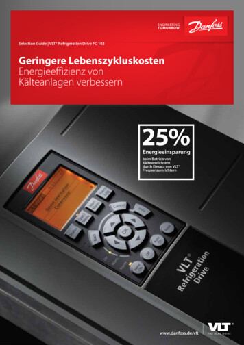
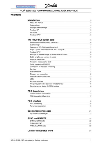
1.4.2 Interior Views1011130BC252.111 1VLT AutomationDrive FC 302Introduction1891614151213(IP 21/54NEMA 1/12)13 (IP 20/Chassis)Figure 1.1 D1 Interior Components4Danfoss A/S 06/2015 All rights reserved.MG34U422
IntroductionInstruction Manual1 110130BC301.11111674253891LCP (local control panel)92RS485 serial bus connector10 Lifting ringRelay 2 (04, 05, 06)3Digital I/O and 24 V power supply11 Mounting holes4Analog I/O connector12 Cable clamp (PE)5USB connector13 Ground6Serial bus terminal switch14 Motor output terminals 96 (U), 97 (V), 98 (W)7Analog switches (A53), (A54)15 Line power input terminals 91 (L1), 92 (L2), 93 (L3)8Relay 1 (01, 02, 03)16 TB5 (IP21/54 only). Terminal block for anti-condensation heaterFigure 1.2 Close-up View: LCP and Control FunctionsNOTICE!For location of TB6 (terminal block for contactor), seechapter 4.6 Motor Connection.1.4.3 Extended Options CabinetsIf an adjustable frequency drive is ordered with one of thefollowing options, it is supplied with an options cabinetthat makes it taller. Line power disconnect with contactorCircuit breakerOversized wiring cabinetRegeneration terminalsLoad share terminalsFigure 1.3 shows an example of an adjustable frequencydrive with an options cabinet. Table 1.2 lists the variants forthe adjustable frequency drives that include input options.Brake chopperLine power disconnectContactorMG34U422Danfoss A/S 06/2015 All rights reserved.5
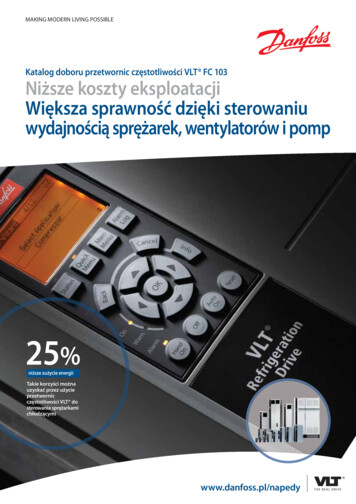
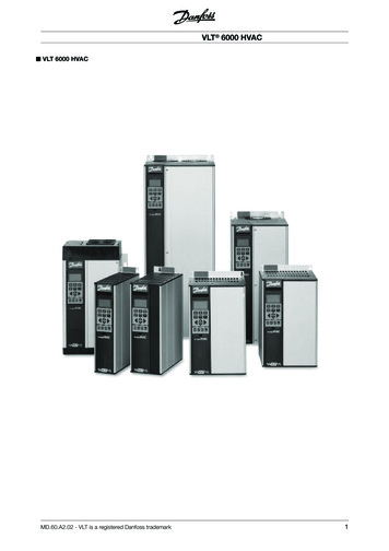
Options unitdesignationsExtension cabinetsPossible optionsD5hD1h enclosure withshort extension. Brake. Circuit breaker. Circuit breaker.D6hD7hD8hD1h enclosure withtall extension.D2h enclosure withshort extension.D2h enclosure withtall extension.130BC539.101 1VLT AutomationDrive FC 302IntroductionDisconnect.Contactor.Contactor r withdisconnect.Table 1.2 Overview of Extended OptionsThe D7h and D8h adjustable frequency drives (D2h plusoptions cabinet), include an approx. 200 mm (8 in)pedestal for floor mounting.There is a safety latch on the front cover of the optionscabinet. If the adjustable frequency drive is supplied with aline power disconnect or circuit breaker, the safety latchprevents the cabinet door from being opened while theadjustable frequency drive is energized. Before openingthe door of the adjustable frequency drive, open thedisconnect or circuit breaker (to de-energize the adjustablefrequency drive) and remove the cover of the optionscabinet.1754[69.1]For adjustable frequency drives purchased with adisconnect, contactor or circuit breaker, the nameplatelabel includes a type code for a replacement that does notinclude the option. If there is a problem with theadjustable frequency drive, it is replaced independently ofthe options.Figure 1.3 D7h enclosure6Danfoss A/S 06/2015 All rights reserved.MG34U422
IntroductionInstruction Manual1.4.4 Block Diagram of the AdjustableFrequency Drive1 1AreaTitleFunctions Input power, internalprocessing, output, and motorcurrent are monitored toprovide efficient operationand control. User interface and externalcommands are monitored andperformed. Status output and control canbe provided.Figure 1.4 is a block diagram of the internal components ofthe adjustable frequency drive.8Control circuitryTable 1.3 Legend to Figure 1.4AreaTitle 1Line power input2Rectifier3DC bus45DC reactorsCapacitor bank7The rectifier bridge convertsthe AC input to DC current tosupply inverter power. Intermediate DC bus circuithandles the DC current. Filter the intermediate DCcircuit voltage. Prove line transientprotection. Reduce RMS current. Reduce harmonics on the ACinput. Stores the DC power.InverterOutput to motorMG34U4223-phase AC line power supplyto the adjustable frequencydrive. 6Figure 1.4 Block Diagram of the Adjustable Frequency DriveFunctions Raise the power factorreflected back to the line.Provides ride-throughprotection for short powerlosses.Converts the DC into acontrolled PWM AC waveformfor a controlled variableoutput to the motor.1.4.5 Enclosure Types and Power RatingsFor enclosure types and power ratings of the adjustablefrequency drives, refer to chapter 8.9 Power Ratings, Weightand Dimensions.1.5 Approvals and CertificationsMore approvals and certifications are available. Contact thelocal Danfoss partner. Adjustable frequency drives ofenclosure type T7 (525–690 V) are UL-certified for only525–600 V.The adjustable frequency drive complies with UL 508Cthermal memory retention requirements. For moreinformation, refer to the section Motor Thermal Protectionin the product-specific Design Guide.1.6 DisposalRegulated 3-phase outputpower to the motor.Danfoss A/S 06/2015 All rights reserved.Do not dispose of equipment containingelectrical components together withdomestic waste.Collect it separately in accordance withlocal and currently valid legislation.7
2 2VLT AutomationDrive FC 302Safety2 SafetyWARNING2.1 Safety SymbolsThe following symbols are used in this manual:WARNINGIndicates a potentially hazardous situation that couldresult in death or serious injury.CAUTIONIndicates a potentially hazardous situation that couldresult in minor or moderate injury. It can also be used toalert against unsafe practices.NOTICE!Indicates important information, including situations thatcan result in damage to equipment or property.UNINTENDED STARTWhen the adjustable frequency drive is connected to ACline power, DC supply, or load sharing, the motor maystart at any time. Unintended start during programming,service, or repair work can result in death, serious injury,or property damage. The motor can start via an externalswitch, a serial bus command, an input reference signalfrom the LCP, or after a cleared fault condition.To prevent unintended motor start: Disconnect the adjustable frequency drive fromline power. Press [Off/Reset] on the LCP beforeprogramming parameters. Completely wire and assemble the adjustablefrequency drive, motor, and any drivenequipment before connecting the adjustablefrequency drive to AC line power, DC supply, orload sharing.2.2 Qualified PersonnelCorrect and reliable transport, storage, installation,operation, and maintenance are required for the troublefree and safe operation of the adjustable frequency drive.Only qualified personnel are allowed to install and operatethis equipment.Qualified personnel are defined as trained staff who areauthorized to install, commission, and maintain equipment,systems, and circuits in accordance with pertinent laws andregulations. Additionally, the qualified personnel must befamiliar with the instructions and safety measuresdescribed in this instruction manual.2.3 Safety PrecautionsWARNINGDISCHARGE TIMEThe adjustable frequency drive contains DC linkcapacitors that can remain charged even when theadjustable frequency drive is not powered. Failure towait the specified time after power has been removedbefore performing service or repair work could result indeath or serious injury.1.Stop the motor.2.Disconnect AC line power, permanent magnettype motors, and remote DC link powersupplies, including battery backups, UPS, andDC link connections to other adjustablefrequency drives.3.Wait for the capacitors to discharge fully beforeperforming any service or repair work. Theduration of waiting time is specified in Table 2.1.WARNINGHIGH VOLTAGEAdjustable frequency drives contain high voltage whenconnected to AC line power input, DC supply, or loadsharing. Failure to perform installation, start-up, andmaintenance by qualified personnel can result in deathor serious injury. 8Only qualified personnel may perform installation, start-up, and maintenance.Danfoss A/S 06/2015 All rights reserved.MG34U422
SafetyInstruction ManualVoltage [V]Power range [kW (hp)]Minimum waiting time(minutes)3x40090–250 (125–350)203x400110–315 (150–425)203x500110–315 (150–425)203x500132–355 (175–475)203x52555–250 (75–350)203x52590–315 (125–425)203x69055–250 (75–350)203x690110–315 (150–425)20CAUTION2 2INTERNAL FAILURE HAZARDAn internal failure in the adjustable frequency drive canresult in serious injury when the adjustable frequencydrive is not properly closed. Ensure that all safety covers are in place andsecurely fastened before applying power.Table 2.1 Discharge TimeWARNINGLEAKAGE CURRENT HAZARDLeakage currents exceed 3.5 mA. Failure to ground theadjustable frequency drive properly can result in deathor serious injury. Ensure the correct grounding of the equipmentby a certified electrical installer.WARNINGEQUIPMENT HAZARDContact with rotating shafts and electrical equipmentcan result in death or serious injury. Ensure that only trained and qualified personnelperform installation, start-up, and maintenance. Ensure that electrical work conforms to nationaland local electrical codes. Follow the procedures in this manual.WARNINGUNINTENDED MOTOR ROTATIONWINDMILLINGUnintended rotation of permanent magnet motorscreates voltage and can charge the unit, resulting indeath, serious injury, or equipment damage. Ensure that permanent magnet motors areblocked to prevent unintended rotation.MG34U422Danfoss A/S 06/2015 All rights reserved.9
3 Mechanical Installation3.1 UnpackingNOTICE!3.1.1 Items SuppliedDo not remove the nameplate from the adjustablefrequency drive (loss of warranty).Items supplied may vary according to product configuration.3.1.2 Storage 124567Make sure the items supplied and the informationon the nameplate correspond to the order confirmation.Check the packaging and the adjustablefrequency drive visually for damage caused byinappropriate handling during shipment. File anyclaim for damage with the carrier. Retaindamaged parts for clarification.VLTRAutomation Drivewww.danfoss.comT/C: FC-302PK37T2E20H1BGXXXXSXXXXA6BKC4XXXD0P/N: 131X3537S/N: 010122G4300.37kW/ 0.50HP9IN: 3x200-240V 50/60Hz 2.2AOUT: 3x0-Vin 0-1000Hz 2.4AooCHASSIS/ IP20 Tamb.50 C/122 FCAUTION:See manual for special condition/mains fuse voir manual de conditions speclales/fusiblesWARNING:Stored charge, wait 4 min. attendez 4 min.Charge residuelle,NOTICE!In environments with airborne liquids, particles, orcorrosive gases, ensure that the IP/type rating of theequipment matches the installation environment. Failureto meet requirements for ambient conditions can reducethe lifetime of the adjustable frequency drive. Ensurethat requirements for air humidity, temperature, andaltitude are met.Voltage [V] Altitude restrictions380–500At altitudes above 3000 m (10,000 ft), contactDanfoss regarding PELV525–690At altitudes above 2000 m (6,600 ft), contactDanfoss regarding PELVTable 3.1 Installation in High AltitudesFor detailed ambient conditions specifications, refer tochapter 8.4 Ambient Conditions.3.3 MountingNOTICE!1Type code2Order number3Serial number4Power rating5Input voltage, frequency and current (at low/highvoltages)6Output voltage, frequency and current (at low/highvoltages)Improper mounting can result in overheating andreduced performance.7Enclosure type and IP protection rating8Maximum ambient temperature9Certifications10Discharge time (Warning)103.2 Installation EnvironmentsMADE IN DENMARKListed 76X1 E134261 Ind. Contr. Eq.Figure 3.1 Product Nameplate (Example)Ensure that the requirements for storage are fulfilled. Referto chapter 8.4 Ambient Conditions for further details.8*1 3 1 X 3 5 3 7 0 1 0 1 2 2 G 4 3 0 *103130BD600.103 3VLT AutomationDrive FC 302Mechanical InstallationCooling Ensure that top and bottom clearance for aircooling is provided. Clearance requirement: 225mm (9 in). Consider derating for temperatures startingbetween 45 C (113 F) and 50 C (122 F) andelevation 1000 m (3,300 ft) above sea level. Seethe adjustable frequency drive design guide fordetailed information.The adjustable frequency drive utilizes a backchannelcooling concept that removes heatsink cooling air. Theheatsink cooling air carries approximately 90% of the heatout of the backchannel of the adjustable frequency drive.Danfoss A/S 06/2015 All rights reserved.MG34U422
Mechanical InstallationInstruction Manual Duct cooling. A backchannel cooling kit isavailable to direct the heatsink cooling air out ofthe panel when an IP20/chassis adjustablefrequency drive is installed in a Rittal enclosure.Use of this kit reduces the heat in the panel andsmaller door fans can be specified on theenclosure. Cooling out the back (top and bottom covers).The backchannel cooling air can be ventilated outof the room so that the heat from thebackchannel is not dissipated into the controlroom.NOTICE!A door fan(s) is required on the enclosure to remove theheat not contained in the backchannel of the adjustablefrequency drive. It also removes any additional lossesgenerated by other components inside the adjustablefrequency drive. Calculate the total required air flow sothat the appropriate fan(s) can be selected.Secure the necessary airflow over the heatsink. The flowrate is shown in Table 3.2.FrameDoor fan/top fanD1h/D3h/D5h/D6h 102 m3/hr (60 CFM)D2h/D4h/D7h/D8h 204m3/hr176FA245.10Redirect the backchannel air from the panel or room byusing:3 3Figure 3.2 Recommended Lifting MethodWARNINGRISK OF INJURY OR DEATHThe lifting bar must be able to handle the weight of theadjustable frequency drive to ensure that it does notbreak during lifting. See chapter 8.9 Power Ratings, Weight andDimensions for the weight of the differentenclosure types. Maximum diameter for bar: 2.5 cm (1 inch).Heatsink fan420 m3/hr (250 CFM)(120 CFM) 840 m3/hr (500 CFM)Table 3.2 AirflowLiftingAlways lift the adjustable frequency drive using thededicated lifting eyes. Use a bar to avoid bending thelifting holes.The angle from the top of the adjustablefrequency drive to the lifting cable: 60 orgreater.Failure to follow recommendations could result in deathor serious injury.MountingMG34U4221.Ensure that the strength of the mounting locationsupports the unit weight.2.Place the unit as near to the motor as possible.Keep the motor cables as short as possible.3.Mount the unit vertically to a solid flat surface toprovide cooling airflow. Ensure free space forcooling.4.Ensure the access to open the door.5.Ensure the cable entry from the bottom.Danfoss A/S 06/2015 All rights reserved.11
4 4Electrical InstallationVLT AutomationDrive FC 3024 Electrical Installation4.1 Safety InstructionsWire type and ratingsSee chapter 2 Safety for general safety instructions.WARNINGINDUCED VOLTAGEInduced voltage from output motor cables that runtogether can charge equipment capacitors even with theequipment turned off and locked out. Failure to runoutput motor cables separately or use shielded cables ormetal conduits could result in death or serious injury. run output motor cables separately, oruse shielded cables or metal conduitsCAUTIONSHOCK HAZARDThe adjustable frequency drive can cause a DC current inthe PE conductor. Failure to follow the recommendationbelow means the RCD may not provide the intendedprotection. When a residual current-operated protectivedevice (RCD) is used for protection againstelectrical shock, only an RCD of Type B ispermitted on the supply side.The adjustable frequency drive is supplied with Class 20motor overload protection.Overcurrent protection 12All wiring must comply with local and nationalregulations regarding cross-section and ambienttemperature requirements. Power connection wire recommendation:Minimum 75 C (167 F)-rated copper wire.See chapter 8.1 Electrical Data and chapter 8.5 Cable Specifications for recommended wire sizes and types.4.2 EMC-compliant InstallationTo obtain an EMC-compliant installation, follow theinstructions provided in Additional protective equipment, such as shortcircuit protection or motor thermal protectionbetween adjustable frequency drive and motor, isrequired for applications with multiple motors.Input fusing is required to provide short circuitand overcurrent protection. If not factorysupplied, the installer must provide the fuses. Seemaximum fuse ratings in chapter 8.7 Fuses.Chapter 4.3 Grounding.Chapter 4.4 Wiring Schematic.Chapter 4.6 Motor Connection.Chapter 4.8 Control Wiring.4.3 GroundingWARNINGLEAKAGE CURRENT HAZARDLeakage currents exceed 3.5 mA. Failure to ground theadjustable frequency drive properly could result in deathor serious injury. NOTICE! Ensure the correct grounding of the equipmentby a certified electrical installer.For electrical safety Ground the adjustable frequency drive inaccordance with applicable standards anddirectives. Use a dedicated ground wire for input power,motor power, and control wiring. Do not ground one adjustable frequency drive toanother in a "daisy chain" fashion. Keep the ground wire connections as short aspossible. Follow the motor manufacturer wiringrequirements. Minimum cable cross-section: 10 mm2 (or 2-ratedground wires terminated separately).Danfoss A/S 06/2015 All rights reserved.MG34U422
Electrical InstallationInstruction ManualFor EMC-compliant installation Establish electrical contact between the cableshield and the adjustable frequency driveenclosure by using metal cable connectors or byusing the clamps provided on the equipment. Use high-strand wire to reduce electricalinterference.4 4 Do not use pigtails.NOTICE!POTENTIAL EQUALIZATIONRisk of electrical interference, when the ground potentialbetween the adjustable frequency drive and the controlsystem is different. Install equalizing cables between thesystem components. Recommended cable cross-section:16 mm2.MG34U422Danfoss A/S 06/2015 All rights reserved.13
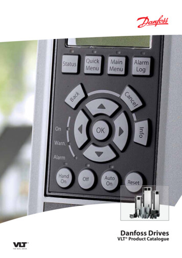
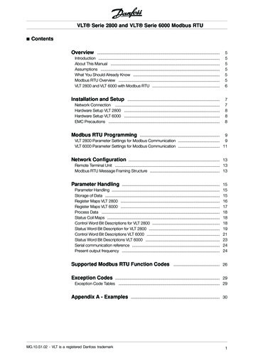
VLT AutomationDrive FC 302Electrical InstallationTB5230 VAC50/60 HzLoad Share 10 VDCSwitch ModePower Supply10 VDC 24 VDC15 mA 200 mA -88 (-)89 ( )50 ( 10 V OUT)(R ) 82ONONA54 U-I (S202)54 (A IN)Relay1ON 0-20 mAOFF 0-10 V030255 (COM A IN)Relay20613 ( 24 V OUT)05P 5-0018 (D IN)24 V (NPN)0 V (PNP)0419 (D IN)24 V (NPN)0 V (PNP)(COM A OUT) 39(A OUT) 4220 (COM D IN)24 VONS801/Bus Term.OFF-ONON Terminated1OFF Open1 224 V24 V (NPN)0 V (PNP)0V29 (D IN/OUT)Brakeresistor240 VAC, 2A400 VAC, 2A0112 ( 24 V OUT)27 (D IN/OUT)Motor(R-) 81A53 U-I (S201)53 (A IN)1 20 VDC - 10 VDC0/4-20 mA(U) 96(V) 97(W) 98(PE) 991 20 VDC - 10 VDC0/4-20 mA91 (L1)92 (L2)93 (L3)95 PE 3 PhasepowerinputAnti-condensation heater (optional)TB6 Contactor (optional)230 VAC50/60 Hz4 4R1130BC548.124.4 Wiring Schematic25V240 VAC, 2A400 VAC, 2AAnalog Output0/4-20 mABrake Temp(NC)24 V (NPN)0 V (PNP)S8010V32 (D IN)24 V (NPN)0 V (PNP)33 (D IN)24 V (NPN)0 V (PNP)RS-485Interface37 (D IN) - option0V(P RS-485) 68RS-485(N RS-485) 69(COM RS-485) 61(PNP) Source(NPN) SinkFigure 4.1 Basic Wiring SchematicA Analog, D Digital*Terminal 37 (optional) is used for Safe Torque Off. For Safe Torque Off installation instructions, refer to the Safe Torque OffInstruction Manual for Danfoss VLT Adjustable Frequency Drives.**Do not connect cable shield.14Danfoss A/S 06/2015 All rights reserved.MG34U422
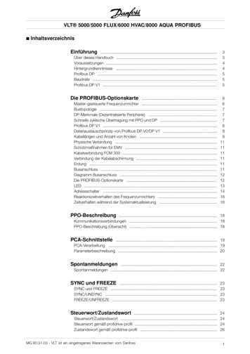
Instruction Manual130BE143.10Electrical Installation4.5 AccessAll terminals to the control cables are located underneaththe LCP on the inside of the adjustable frequency drive. Toaccess, open the door (IP21/54) or remove the front panel(IP20).4.6 Motor Connection4 4WARNINGINDUCED VOLTAGEInduced voltage from output motor cables that runtogether can charge equipment capacitors even with theequipment turned off and locked out. Failure to runoutput motor cables separately or use shielded cables ormetal conduits could result in death or serious injury. Comply with local and national electrical codesfor cable sizes. For maximum wire sizes, seechapter 8.1 Electrical Data. Follow the motor manufacturer wiringrequirements. Motor wiring knockouts or access panels areprovided at the base of IP21 (NEMA1/12) andhigher units. Do not wire a starting or pole-changing device(for example, Dahlander motor or slip ringinduction motor) between the adjustablefrequency drive and the motor.StopStartLine PowerSpeedMotorControlFigure 4.2 Example of Proper Electrical Installation UsingConduitNOTICE!EMC INTERFERENCERun cables for line power input, motor wiring andcontrol wiring in three separate metallic conduits. Failureto isolate power, motor and control cables can result inunintended behavior or reduced performance. Minimum200 mm (7.9 in) clearance between line power input,motor and control cables is required.MG34U422Procedure1.Strip a section of the outer cable insulation.2.Position the stripped wire under the cable clampto establish mechanical fixation and electricalcontact between the cable shield and ground.3.Connect the ground wire to the nearestgrounding terminal in accordance with thegrounding instructions provided inchapter 4.3 Grounding, see Figure 4.3.4.Connect the 3-phase motor wiring to terminals96 (U), 97 (V), and 98 (W), see Figure 4.3.5.Tighten the terminals in accordance with theinformation provided in chapter 8.8 ConnectionTightening Torques.Danfoss A/S 06/2015 All rights reserved.15
VLT AutomationDrive FC 302UV9697130BD531.10Electrical InstallationW984 4SECTION A-AMAINS TERMINALSASECTION B-BMOTOR TERMINALSB130BC305.10Figure 4.3 Motor ConnectionMAINS TERMINALMOTORTERMINAL200[ 7.9 ]94[ 3.7 ]GROUND88[ 3.5 ]SU0[ 0.0 ]244[ 9.6 ]293[ 11.5 ]224[ 8.8 ]V263[ 10.4 ]T185[ 7.3 ]101[ 4.0 ]R140[ 5.5 ]33[ 1.3 ]A62[ 2.4 ]0[ 0.0 ]272[ 10.7 ]0[ 0.0 ]B163[ 6.4 ]3X M8x20 STUDWITH NUT0[ 0.0 ]WFigure 4.4 Terminal Locations, D1h16Danfoss A/S 06/2015 All rights reserved.MG34U422
Instruction ManualSECTION A-AMAINS TERMINALSSECTION B-BMOTOR TERMINALS ANDBRAKE TERMINALSABMAINS TERMINAL130BC332.10Electrical InstallationMOTOR TERMINAL331.2[ 13 ]GROUND168.4[ 7]GROUND143.4[ 6]168.4 GROUND[ 7]143.4 GROUND[ 6]S254.7[ 10 ]299.8[ 12 ]V353.8[ 14 ]183.5[ 7]T245.8[ 10 ]R125.8[ 5]0.0[ 0]68.1[ 3]284.2[ 11 ]377.6[ 15 ]42.4[ 2]AB0.0[ 0]4X M10x20 STUDWITH NUT0.0[ 0]0.0[ 0]4 4211.1[ 8]WUASECTION B-BMOTOR TERMINALS ANDBRAKE TERMINALSBRAKEBBRAKETERMINAL130BC302.10152[ 6.0 ]SECTION A-AMAINS TERMINALS217[ 8.5 ]Figure 4.5 Terminal Locations, D2h292[ 11.5 ]188[ 7.4 ]MAINSTERMINALMOTOR TERMINAL83[ 3.3 ]TV0[ 0.0 ]223[ 8.8 ]R244[ 9.6 ]145[ 5.7 ]W184[ 7.2 ]62[ 2.4 ]U101[ 4.0 ]S22[ 0.9 ]0[ 0.0 ]B290[ 11.4 ]A272[ 10.7 ]0[ 0.0 ]0[ 0.0 ]Figure 4.6 Terminal Locations, D3hMG34U422Danfoss A/S 06/2015 All rights reserved.17
VLT AutomationDrive FC 3022150[2.0]98[3.9]130BC533.10Electrical Installation190[7.5]75[3.0]4 41Front view2Side view376[ 14.8 ]MAINS TERMINALSECTION B-BMOTOR TERMINALS ANDBRAKE TERMINALSBRAKETERMINALS130BC333.10B293[ 11.5 ]ASECTION A-AMAINS TERMINALS236.8[ 9]Figure 4.7 Load Share and Regeneration Terminals, D3hBRAKE / REGENTERMINAL319[ 12.6 ]MOTOR TERMINAL319[ 12.6 ]WT0[ 0.0 ]211[ 8.3 ]U265[ 10.4 ]S149[ 5.8 ]33[ 1.3 ]R91[ 3.6 ]AB0[ 0.0 ]284[ 11.2 ]0[ 0.0 ]0[ 0.0 ]306[ 12.1 ]255[ 10.0 ]200[ 7.9 ]VFigure 4.8 Terminal Locations, D4h18Danfoss A/S 06/2015 All rights reserved.MG34U422
Instruction Manual130BC534.10Electrical Installation1295[3.7]126[4.9]1Front view2Side view75[3.0]190[7.5]4 4A-AABB-B12221[ 8.7 ]227[ 9]196[ 7.7 ]148[ 5.8 ]118[ 4.6 ]90[ 3.6 ]0[ 0]Line power terminalsBrake terminals3Motor terminals153[ 6]193[ 7.6 ]249[ 9.8 ]S0[ 0]113[ 4.4 ]V206[ 8.1 ]U260[ 10.2 ]46[ 1.8 ]146[ 5.8 ]182[ 7.2 ]221[ 8.7 ]A99[ 3.9]45[ 1.8 ]R23B0[ 0]41130BC535.11Figure 4.9 Load Share and Regeneration Terminals, D4hWT4Ground terminalsFigure 4.10 Terminal Locations, D5h with Disconnect OptionMG34U422Danfoss A/S 06/2015 All rights reserved.19
130BC536.11VLT AutomationDrive FC 302Electrical InstallationV0[ 0]3362[ 1.3 ][ 2.4 ]101140[4 ][ 5.5 ]163185[ 6.4 ]191[ 7.5 ] [ 7.3 ]224256[ 8.8 ][ 10.1]263[ 10.4]293[ 11.5]SWUR4 41A-AT2B-B727[ 28.6]623[ 24.5]517[ 20.4]511[ 20.1]341Line power terminals2Brake terminals3Motor terminals0[ 0]293[ 11.5 ]246[ 9.7 ]274[ 10.8 ]0[0 ]0[ 0]4Ground terminalsFigure 4.11 Terminal Locations, D5h with Brake Option20Danfoss A/S 06/2015 All rights reserved.MG34U422
VMAINS SIDECABLE ]242[9.5]121[4.8]MOTOR SIDECABLE ENTRY224[8.8]15[0.6]50.5[2]SHIELDINGCLAMPSWBRAKE [2.2][3.6]151175 [5.9][6.9] 224[8.8]258[10.2]0[0]42[1.7]77[3]126[5] 160[6.3]209[8.2]244[9.6]285[11.2]118[4.6]MAINS TERMINALMOTOR TERMINAL16.5[0.7]0[0]R4 4BRAKE TERMINAL154[6.1]SHIELDINGCLAMPS0[0]SECTION VIEWBRAKE TERMINAL233[9.2]210[8.3]MOTOR TERMINAL5X MI0 X 20 STUDWITH 3]101[4]MAINS TERMINAL4X MI0 X 20 STUDWITH NUT248271[10.7]10[0.4][8.2]MOTOR TERMINALMAINS TERMINALCD35[1.4]SECTION VIEWMAINS TERMINALMOTOR TERMINALInstruction Manual123.1[5] 179199 [7.1][7.8] 209Electrical InstallationM830[1.2]111[4.4]BOTTOM VIEWFigure 4.12 Oversized Wiring Cabinet, D5hMG34U422Danfoss A/S 06/2015 All rights reserved.21
A-AB-BBA130BC537.12VLT AutomationDrive FC 3021458[18.0 ]2227[8.9]195[7.7]5153[6.0 ]123[4.8 ]96[3.8]1Line power terminals2TB6 terminal block for contactor3Brake terminals4Motor 9]146147[5.8][5.8]182193[7.2]221 [7.6 ] 249[8.7][9.8]260[10.2]286[11.2 ]0[0.0]0[0.0]3206[8.1]4 40[0.0]Electrical InstallationW5Ground terminalsFigure 4.13 Terminal Locations, D6h with Contactor Option22Danfoss A/S 06/2015 All rights reserved.MG34U422
Instruction Manual130BC538.12Electrical InstallationAA-A4 4125225[ 8.9 ]431Brake terminals2TB6 terminal block for contactor3Motor terminals4G
This instruction manual is intended for use by qualified personnel. Read and follow the instruction manual to use the adjustable frequency drive safely and professionally, and pay particular attention to the safety instructions and general warnings. Keep this instruction manual available with the adjustable frequency drive at all times.