Transcription
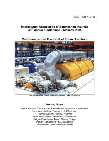
IMIA – WGP 42 (05)International Association of Engineering Insurers38th Annual Conference – Moscow 2005Maintenance and Overhaul of Steam TurbinesHMN Series Steam Turbine – Courtesy Siemens Power CorporationWorking GroupJohn Latcovich, The Hartford Steam Boiler Inspection & InsuranceCompany, Hartford, Connecticut (Chairman)Thomas Åstrom, Pohjola, HelsinkiPeter Frankhuizen, Praevenio, AmsterdamSeigou Fukushima, Tokyo Marine, TokyoHåkan Hamberg, If P&C, SundsvallStefan Keller, Swiss National, Basel
IMIA – WGP 42 (05)Maintenance and Overhaul of Steam TurbinesTable of ContentsSectionTitlePageTable of Contents2Executive Summary41.Introduction52.Steam Turbine Component Characteristics, FailureMechanisms, Arrangements and Applications6A.Turbine Component Characteristics and Failure Mechanisms6A.1A.2A.3A.4A.5A.6A.7A.8A.9A.10Steam Turbine BladingDiscs, Rotors, Shafts, Blade Rings, Shells, and DiaphragmsRotor Forgings with Center BoresBearings and Lubrication SystemsSteam and Oil SealsStop, Trip & Throttle, and Intercept ValvesGovernor/Control ValvesAdmission, Extraction, and Non-Return Valves (NRV)Steam Line Connections and DrainsTurbine Overspeed Protection and Trip Logic67889910101111B.Steam Turbine Arrangements and Applications12B.1B.2B.3B.4B.5B.6B.7B.8B.9Type of SteamExhaust System ConfigurationGrouping and Number of Turbine StagesTurbine ArrangementsSingle Stage Small Steam TurbinesMultistage Medium Size Steam TurbinesSingle Casing Admission/Extraction Multistage Steam TurbinesSingle Casing Non-Reheat Multiple Stage Steam TurbinesSingle Casing Reheat Multiple Stage Combined Cycle SteamTurbinesB.10 Multiple Casing Multiple Stage Reheat Steam Turbines212131415161617181819
IMIA – WGP 42 (05)Table of Contents (Continued)SectionTitlePage3.Monitoring, Operations, Maintenance, andTraining t MonitoringWater and Steam Purity MonitoringWater Induction MonitoringCondition Monitoring20222223B.Operations, Maintenance, and Training Infrastructure24B.1B.2B.3OperationsMaintenance ManagementTraining2425254.Steam Turbine Availability and Failure Experience275.Scheduled Maintenance and Overhaul Practices30A.B.C.3032346.U.S. Maintenance PracticesEuropean Maintenance PracticesJapanese Maintenance PracticesApproaches/Methodologies/Criteria for Establishing LongerTime Intervals between Major Overhauls37A.B.C.D.E.F.G.37373838393941Management Directed IntervalProcess and Criticality Driven IntervalsTurbine Manufacturer’s IntervalsElectric Power Research Institute (EPRI)VGB StandardsRisk-Based MethodologiesReliability Centered or Condition Based Maintenance(RCM or CBM)7.Issues with New Steam Turbine Technologies andApplications438.Conclusions463
IMIA – WGP 42 (05)Executive SummarySteam turbines provide a means of converting saturated, superheated, or supercritical steamfrom boilers or heat recovery steam generators (HRSG) into rotational torque and power.Consequently steam turbines are utilized to drive a variety of equipment types of numeroussizes and speeds in just about every industry segment including power generation, pulp andpaper, iron and steel, combined heat and power, and chemical, oil and gas industries.While there are substantial differences in the design, complexity, application, steam conditions,and size of steam turbines, they all are fundamentally the same. They perform the samefunction, utilize similar major components and supporting systems, and are subjected to thesame failure mechanisms. To support reliable turbine operation, there needs to be an effectiveinfrastructure in place for monitoring the operating conditions, water/steam quality, and health ofthe steam turbine, for having and using written operating/maintenance procedures, for utilizing amaintenance management system to schedule/track maintenance, and for conducting trainingfor personnel on an ongoing basis.There have been numerous causes of steam turbine failures worldwide. The highest frequencyevents have been loss of lube oil incidents while the highest severity events have beenoverspeed events. Typically, higher frequency and higher severity events have beenblade/bucket failures, particularly in the low pressure (LP) section of the turbine where theblading experienced a number of failure mechanisms (stress corrosion cracking (SCC), erosion,foreign object damage (FOD)) which ultimately led to failure.With regards to maintenance practices in North America and Europe, there are no regulatorymaintenance practices or intervals specified for non-nuclear steam turbines regardless of theindustry or application. As such, the frequencies and tasks are defined by the turbinemanufacturers, consultants, industry organizations, plant personnel, plant processrequirements, or insurers based on past experience. In Japan, however, there are regulatoryrequirements for periodic maintenance. However, regardless of the area of the world, therecommended scheduled maintenance requirements for steam turbines are quite similar. Forestablishing longer time intervals between major overhaul outages, there are a number ofdifferent approaches which are utilized today worldwide. Regardless of the approach, it isimportant that the methodologies effectively establish the overhaul intervals based on thehighest risk portions of the steam turbine.The technologies being incorporated into new steam turbines are more sophisticated, requireoperation at higher pressures and temperatures, and generally have smaller clearances toimprove efficiency. While these technologies have not caused any large losses, the inherentrisk exposures are increasing and the in-service experience with these technologies needs to bemonitored.In summary, maintenance tasks and frequencies should be prioritized towards the portions ofthe steam turbine that have the highest risk. This usually means protecting the steam turbinefrom overspeeds, water induction, loss of lube oil, corrosive steam, and sticking valves thatcould cause major damage to the turbine, and conducting internal inspections of the turbineflowpath, shells and rotors for failure mechanism damage (creep, erosion, corrosion, fatigue,thermal fatigue, SCC) in order to detect the damage early enough to prevent a subsequentmajor failure.4
IMIA – WGP 42 (05)1. IntroductionSteam turbines are utilized in numerous industries to drive boiler fans, boiler feed and waterpumps, process and chiller compressors, blast furnace blowers, paper mill line shafts, sugar millgrinders, and generators in a variety of industries and applications. Consequently, steamturbines can range from being small and simple in design/construction to large, highly complexdesigns/arrangements consisting of multiple sections and multiple shafts.Specifying the desired maintenance and overhaul intervals for steam turbines, therefore, has totake into account the design/construction of the turbine as well as the industry and applicationutilizing the turbine. Besides the configuration and industry associated with the steam turbine,the infrastructure for monitoring, operations and maintenance including specific practices, andsteam quality can have a major effect on the reliability of steam turbines regardless of theindustry or application.In the next several sections of this paper, several pertinent aspects of steam turbines will beaddressed. The discussions have been organized in a sequence beginning with steam turbinecomponent characteristics, failure mechanisms, arrangements and applications. Thesediscussions are followed by what infrastructures should be in place to operate and maintainsteam turbines, what has failed based on past experience, and what maintenance should beconducted to minimize the risk of failure. And lastly, the discussions include what should betaken into account for determining longer major overhaul intervals and what effects the newsteam turbine technologies may have on scheduled maintenance and overhaul intervals.5
IMIA – WGP 42 (05)2. Steam Turbine Component Characteristics,Failure Mechanisms, Arrangements and ApplicationsSteam turbines are fundamentally the same regardless of whether they drive a simple 500 shafthorsepower (SHP) fan or drive a 1,000 MW generator. In all cases, steam is expanded throughrows of stationary and rotating blading which convert the energy in the steam into mechanicalenergy. While the functions are the same for all steam turbines, the designs are sufficientlydifferent to necessitate brief discussions on the important components, their characteristics andfailure mechanisms, and how they are arranged or organized as these attributes do affect steamturbine maintenance tasks and frequencies.2.ATurbine Component Characteristics and Failure Mechanisms2.A.1 Steam Turbine BladingSteam turbines produce power by converting the energy in steam provided from a boiler or heatrecovery steam generator (HRSG) into rotational energy as the steam passes through a turbinestage. A turbine stage normally consists of a row of stationary blading and a row of rotatingblading. The purpose of the stationary blading is to direct the flow of the passing steam to therotating blading at the proper angle and velocity for the highest efficiency and extraction ofpower. The purpose of the rotating blading is to convert the directed mass flow and steamvelocity into rotational speed and torque. Stationary blading may be referred to as nozzles,vanes, stators, partitions, and stationary blading while rotating blades may be referred to asbuckets, blades, and rotating blading. A turbine may have a single row or stage of stationaryand rotating blading or may have multiple rows or stages of blading.Steam turbine blading have different shapes which are referred to as either impulse blading orreaction blading. Impulse blading is characterized by high velocity fluids entering the turbineblade, by a blade profile that efficiently turns the direction of the fluid with little pressure change,and by decreasing the velocity of the fluid as it leaves the blade to extract energy. Typicalimpulse blades are crescent or U-shaped and may not always be symmetrical.Reaction blading is characterized by high velocity fluids entering the turbine blade, but not ashigh as impulse velocity levels, by a blade profile that efficiently allows the fluid to expand whilepassing through the blade, and by decreasing both the velocity and pressure of the fluid as itexits from the blade to extract energy. Typical reaction blading has tear-drop shaped leadingedges with a tapered thickness to the trailing edge. The blades may have twist to their shapewhich may range from low amounts of twist or reaction at the base of the blade to high twist orreaction at the tip of the blade.Impulse type blading is typically utilized in the high pressure or front sections of the steamturbine while reaction blading is utilized in the lower pressure or aft sections of the turbine. Manyof today’s new steam turbines, however, are utilizing reaction blading in all stages of the turbineincluding the high pressure sections. Regardless of the blading type, the blade tips may becovered with bands peened to their tips which connect several blades together in groups, or theblades may have integral shrouds which are part of the blades, or may have no tip cover bandsor shrouds (free standing). The blade shrouds and cover bands are utilized to keep the passingsteam from leaking over the tip of the blades which reduces efficiency and power output and toreduce or dampen the vibration characteristics of the blading. Both stationary and rotatingblading can have shrouds or covers depending on the turbine design. The number of blades in6
IMIA – WGP 42 (05)a group that are covered by shrouds is dependent upon the vibration characteristics of thespecific machine. For some designs, thick wires (called tie wires) are brazed into or betweenblades to dampen the vibration levels of the blades or groups of blades. In other cases, the tiewires are installed in the blade tips particularly in large blades in the last stages of turbines. Andfor some blade designs, interlocking tip shrouds (z-shaped) and midspan snubbers (contactsurfaces) are utilized to dampen blade vibration, particularly for long last stage turbine blades.Steam turbine blading can be subjected to several failure mechanisms in service. Thesemechanisms are indicated in Table 1 along with the resultant damage and typical causes offailure. For steam turbines to operate with high reliability and availability, the ability toregularly inspect and assess the steam blading condition is important as any of thefailure mechanisms in Table 1 can lead to failure if left undiagnosed or neglected.Table 1 – Steam Turbine Blading Failure ultant DamageExtensive pitting of airfoils,shrouds, covers, bladeroot surfacesAirfoils, shrouds, coverspermanently deformedThinning of airfoils,shrouds, covers, bladerootsFatigueCracks in airfoils, shrouds,covers, blade rootsForeign/DomesticObject Damage(FOD/DOD)Impact damage (dents,dings, etc.) to any part ofthe bladingStress CorrosionCracking (SCC)Cracks in highly stressedareas of the bladingThermal FatigueCracks in airfoils, shrouds,covers, and blade rootsCause(s) of FailureChemical attack from corrosive elements in the steamprovided to the turbineDeformed parts subjected to steam temperatures inexcess of design limits1) Solid particle erosion from very fine debris andscale in the steam provided in the turbine2) Water droplet erosion from steam which istransitioning from vapor to liquid phase in the flowpath1) Parts operated at a vibratory natural frequency2) Loss of part dampening (cover, tie wire, etc.)3) Exceeded part fatigue life design limit4) Excited by water induction incident – water flashesto steam in the flowpathDamage from large debris in steam supplied to theturbine (foreign) or damage from debris generatedfrom an internal turbine failure (domestic) whichcauses downstream impact damage to componentsSpecialized type of cracking caused by the combinedpresence of corrosive elements and high stresses inhighly loaded locationsParts subjected to rapidly changing temperaturegradients where thick sections are subjected to highalternating tensile and compressive stresses duringheat-ups and cooldowns or when a water inductionincident occurs where the inducted cool waterquenches hot parts2.A.2 Discs, Rotors, Shafts, Blade Rings, Shells, and DiaphragmsTo transmit the torque produced in each stage of the turbine, the rotating blading is fastened todiscs or wheels through a specially designed attachment shape at the blade base or root. Theroot shape may be fir-tree, T-slot, or semi-circular fir-tree shaped or may use multiple pins tohold the blades to the discs. The turbine discs may be shrunk fit onto a shaft with an antirotation key or the discs may have been forged with the shaft as an integral assembly. Theoutput shaft from the shrunk fit or integral disc rotor is then connected to the driven equipmentthrough a flange connection or flexible coupling.7
IMIA – WGP 42 (05)Similarly, stationary blading roots may be attached to slots in shells, casings, or blade rings orwhere the stationary blading is welded to support rings to create a stationary blading assemblyreferred to as a diaphragm. Depending on the pressure and temperature of the steam to theturbine, there may be dual sets of shells or casings; an inner shell which holds the stationaryblading and an outer shell which acts as pressure boundary for the turbine as well asaccommodating attachment of blade rings.The mass and thermal inertial of steam turbine rotors and shells can be quite large. As such,the temperature gradients the rotors and shells can encounter during starting and transientsneed to be controlled carefully otherwise there can be serious rubs between the rotating andstationary parts and/or there can be extensive distortion of rotors and/or shells when thegradients are too large or occur too fast.Steam turbine discs, rotors, shafts, shells, blade rings, and diaphragms are subjected tothe same failure mechanisms and causes that apply to steam turbine blading. It is notuncommon to encounter permanent deformation (creep), fatigue cracks (thermal andvibratory), and stress corrosion cracking in discs, rotors, shells, and diaphragms. Unlikeblading, the mechanisms may take longer for the resultant damage to become detectableas these parts tend to be more robust in size.2.A.3 Rotor Forgings with Center BoresIntegrally forged steam turbine rotors manufactured in the past two decades have not had boresmachined in the center of the rotor. The improvements in steel refining and forgingmanufacturing have not necessitated the need to remove impurities and poorly forged materialthat accumulated in the center of older rotors. The presence of the center bore results in ahigh stress in the bore that requires periodic ultrasonic (UT) and eddy current (ET)inspection for cracks.Because of the quality of some of the early forgings, cracks have been found that requireinternal machining of the bore to remove the affected material. It has not been uncommon tofind a few hundred thousand indications during UT inspection that may require additionalanalyses to determine if the indications are cracks and if they are connected to each other,potentially resulting in a unsafe condition. The improvements in UT inspection instrumentationand techniques have also resulted in finding new numbers of defects that were not detectablewith older UT technologies. On the positive side, the presence of the center bore does allow forUT inspection of rotor wheels and blade slots from underneath.2.A.4 Bearings and Lubrication SystemsAs with most rotating machinery, bearings are utilized to support the turbine rotor insidehousings installed in the turbine shells. Depending on the size and number of stages of thesteam turbine, different types of bearings may be utilized. It is common for smaller steamturbines to utilize rolling element bearings while larger turbines will utilize journal and multi-padthrust bearings. Regardless of the type of turbine, there needs to be a complete lubricationsystem that reliably provides clean, cool lube oil to the turbine bearings. For many large steamturbines, shaft lift oil systems are utilized to lift the shaft in their journal bearings during startingand to keep the shaft lubricated during coast down of the turbine rotor after steam to the turbineis shut off. For some turbines, lube oil (usually mineral oil) is utilized to power servomotors andactuators for stop and control valves. In other cases, hydraulic fluids (usually phosphate-ester8
IMIA – WGP 42 (05)type fluids), which can operate at higher pressures and temperatures without ignition, areutilized to provide the required power for the valves.Properly designed and maintained lube oil or hydraulic fluid systems are extremely important.Most oil systems, as a minimum, need to include an oil reservoir with level indication, filters andseparators (particulate and water removal), pumps (primary and emergency backup that areindependent of the primary pump system), pressure switches or sensors to detect loss of oilpressure, and heat exchangers to cool the oil. Of most concern is protecting the turbine fromloss of lube oil incidents which may involve the loss of oil pressure detectors (pressure switchesand controls) or backup lube oil pump(s) and/or their starting logic not working properly.Since oil is utilized to lubricate and cool turbine bearings (and gearbox gears and bearings, ifpresent) and actuate major turbine valves, it is important that the oil be free of dirt, moisture,foaming, and any contaminants which would cause damage to bearings, servomotors, andvalve actuators. Some contaminants are removed by filters, but removal of water requires waterseparators, oil purifiers, or centrifuge type filter systems. Oil coolers can also be a source ofwater as leaks tend to flow from higher pressure (water) to the lower pressure oil system in thecooler. Oil does oxidize in the presence of water and will have a limited life. As such,conducting frequent sampling of lube oil and hydraulic fluids for particulates, water,contaminants, and remaining life is important. The reliability of the lube oil system isimportant as loss of lube incidents have been both frequent and severe events for allsizes of turbines. As such, periodic checks of loss of lube protection devices and logicneed to be conducted.2.A.5 Steam and Oil SealsIn order to keep the steam from going around the stationary and rotating blading, steam turbinesutilize seals to keep the steam confined to the flowpath. Depending on the size and type ofsteam turbine, various types of steam seal designs (carbon rings, labyrinth, retractable labyrinth,brush) may be utilized. These systems are usually pressurized with steam to minimize thepressure differential across these seals so that leakage from the higher pressure parts of theturbine is less likely to occur. Similar type seals are utilized to keep bearing oil confined to thebearing housing. As such, seal systems may have filters, pressure regulators, coolers, and thelike to maintain a seal pressure as required. Severe rubbing of new seals after overhaul orduring transients operation, particularly starting, continues to cause steam turbineforced outages.2.A.6 Stop, Trip & Throttle, and Intercept ValvesImportant to any turbine is the ability to start and stop the machine under normal (controlled)and emergency conditions. For steam turbines, being able to shut off the steam supply quicklyand reliably is required. This is normally accomplished by either main steam (MS) stop valvesor trip and throttle (T&T) valves which are usually installed in the inlet piping to the steamturbine or on the turbine shell. The valves are designed to be leak tight otherwise any steamleakage may keep the turbine turning at low speed after shutdown or causing an overspeedbecause the valve did not close completely after a shutdown or trip.For most applications, actuators for these valves are powered by high-pressure hydraulicsystem fluid or lube system oil. Hydraulic or lube system pressure powers servomotors to openthe valves while loss of oil pressure results in spring-load closing of the valve in a fail-safecondition (closed). For some old and small steam turbines, the stop valve may be a manualvalve with a large handwheel. The same valve may also be used for starting the unit. In9
IMIA – WGP 42 (05)addition, there may be hand operated valves mounted in the nozzle inlet for manually increasingsteam to the turbine.For reheat type steam turbines, which direct steam back to a boiler superheater section forreheating after going through the high pressure section of the turbine, there are additionalvalves installed between the high pressure section and subsequent section of the turbine.Reheat stop valves are used for leak tight protection but a faster active valve called an interceptvalve is installed in series or combination with the reheat stop valves in order to preventoverspeeds. The valves also open with oil pressure and are spring-loaded closed when oilpressure is reduced to zero under trip and overspeed conditions.These valves provide fundamental overspeed protection to the steam turbine and need tobe tested, inspected, and overhauled routinely as contaminants in the steam, wear ofmating valve parts, or damaged valve seats can cause sticking or leaking of these valvesin service.2.A.7 Governor/Control ValvesControl valves are provided on the turbine shell to regulate the flow of steam to the turbine forstarting, increasing/decreasing power, and maintaining speed control with the turbine governorsystem. Several different valve arrangements are utilized. These include a single inlet valvewith separate actuator, cam lift inlet valve assemblies, and bar lift inlet valve assemblies. Thevalve assemblies are normally mounted onto a steam chest that may be integral to the shell orbolted to it. The cam lift valve arrangement utilizes cams, bearings, and bushings which aremounted on camshaft to regulate the position of each valve. A hydraulic servomotor drives arack and pinion connection to the camshaft to indicate the position desired by the governor. Inthe bar lift valve arrangement, a hydraulic cylinder lifts all of the valves attached to the bartogether, but the collars on each valve stem are set at different heights and opening sequencingfor admitting steam during starting and load changes. These valves need to be cycledroutinely to minimize the potential for the valves to stick. When the valves stick open orclosed, the turbine is put into jeopardy as a result of losing the ability to control theturbine (i.e., increase or reduce load).2.A.8 Admission, Extraction, and Non-Return Valves (NRV)In addition to the traditional stop and control valves, many steam turbines have additional portsinstalled on the turbine to admit or extract steam. Steam turbines designed to admit steam notonly at the turbine inlet but also at a lower pressure locations in downstream sections of theturbine are referred to as admission turbines. These turbines are utilized primarily inapplications (steel mills, paper mills, combined cycle plants with triple pressure HRSG’s) whereadditional steam flow at lower pressures is available to make additional power.In addition to providing additional sources of steam to the turbine, the turbine can also be asource of steam for facility services at various pressures and flows. Turbines with this kind ofcapability are referred to as extraction turbines and may be described by the number ofextractions (single, dual, etc.). Steam is taken from the turbine at various stages to match withthe facility’s pressure and flow requirements. The extractions can be categorized as controlledor uncontrolled, as well as automatic or manual. Some extractions are utilized for feedwaterheating. The extraction control valves typically have two functions; to regulate the steam flowexternally and to maintain the extraction steam pressure constant. The valves are hydraulicallyopened and spring-loaded shut. They are, however, not designed to be leak tight and willtypically pass 5% steam flow in the closed position.10
IMIA – WGP 42 (05)Non-return valves (NRV) or check valves are normally installed downstream of the controlledand uncontrolled (i.e., no regulating or control valve) extraction connections to the turbine. Thefunction of the valves is to permit flow of extraction steam in the outgoing direction and prohibitbackward flow into the turbine when turbine extraction pressure is lower than the lines it feeds.The valves are designed to be spring-loaded shut when there is no extraction pressure but theyalso have an air or hydraulically assisted actuator to close the valve when the systems arepressurized. Malfunctioning of extraction NRV’s is the primary cause of overspeeddamage during turbine shutdown. As such, these valves need to be tested, inspected,and overhauled on a frequent basis.2.A.9 Steam Line Connections and DrainsProper connections and support of the steam lines to the turbine are important as well as thesteam drains. If the steam supply lines are putting a load on the turbine, it is likely to cause theturbine to vibrate and will cause mechanical distress to the attachment locations. Similarly,when steam turbines are started, there is a warm-up time to heat the turbine to the propertemperature level before admitting full starting steam. Removal of condensed steam from thestop valve and T&T valves, the turbine shells, and any sealing steam locations during thisperiod of operation is important to prevent damage to the turbine. As such, low point drains,steam traps and drain valves, vents, and the like need to be functioning properly and piping runsorientated so that the water drains out. When drain systems are not operating properly, thepotential for encountering thermally distorted rotors (bowed) and shells (humped) will behigh.2.A.10 Turbine Overspeed Protection and Trip LogicThe most destructive event for a steam turbine is an overspeed event as the steam turbine andits driven equipment are usually catastrophically damaged. These events, while infrequent,continue to occur on both small and larger steam turbines regardless of the vintage, technologylevel, application, or type of control system (digital, analog, hydro-mechanical, mechanical)associated with the steam turbine.A steam turbine may utilize a mechanical overspeed protection system, electronic overspeedprotection system, or combination of systems to maximize protection. The mechanicaloverspeed device consists of a spring-loaded piston mounted in the turbine shaft at the front ofthe turbine. When turbine speed reaches an overspeed condition (i.e., 10% above runningspeed), the piston pops out and hits an oil dump valve lever which causes depressurization ofthe oil supply to the stop, trip and throttle, and intercept valves. This results in all stop andintercept valves immediately closing. Many mechanical systems also utilize a flywheel ballgovernor driven by the turbine shaft. Any change in governor position is converted to a changein oil pressure to the turbine control valve servomotor or actuator. Under overspeed conditions,the flywheel governor will hit the oil dump valve lever to close the steam stop valve.With electronic systems, numerous magnetic speed pickups are installed on the turbine shaft.The turbine control system and software logic will electronically open the oil dump valve todepressurize the oil system and close all stop and intercept valves. There are various versionsof electronic overspeed systems in service. Some include both primary and backup(emergency) systems that operate independently. Some include test switches to test theprimary system for proper operation without actually tripping the turbine
B.2 Maintenance Management 25 B.3 Training 25 4. Steam Turbine Availability and Failure Experience 27 5. Scheduled Maintenance and Overhaul Practices 30 A. U.S. Maintenance Practices 30 B. European Maintenance Practices 32 C. Japanese Maintenance Practices 34 6.
