Transcription
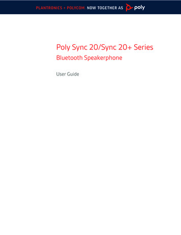
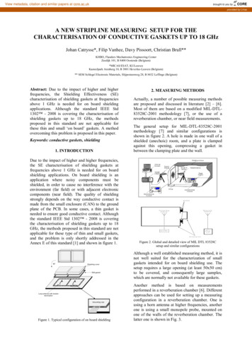
View metadata, citation and similar papers at core.ac.ukbrought to you byCOREprovided by LiriasA NEW STRIPLINE MEASURING SETUP FOR THECHARACTERISATION OF CONDUCTIVE GASKETS UP TO 18 GHzJohan Catrysse*, Filip Vanhee, Davy Pissoort, Christian Brull**KHBO, Flanders Mechatronics Engineering CenterZeedijk 101, B 8400 Oostende (Belgium)*MICAS/ESAT, KULeuvenKasteelpark Arenberg 10, B 3001 Heverlee-Leuven (Belgium)** SEM Schlegel Electronic Materials, Slijpesteenweg 28, B 8432 Leffinge (Belgium)Abstract: Due to the impact of higher and higherfrequencies, the Shielding Effectiveness (SE)characterisation of shielding gaskets at frequenciesabove 1 GHz is needed for on board shieldingapplications. Although the standard IEEE Std1302 - 2008 is covering the characterisation ofshielding gaskets up to 18 GHz, the methodsproposed in this standard are not applicable forthese thin and small ‘on board’ gaskets. A methodovercoming this problem is proposed in this paper.Keywords: conductive gaskets, shielding1. INTRODUCTIONDue to the impact of higher and higher frequencies,the SE characterisation of shielding gaskets atfrequencies above 1 GHz is needed for on boardshielding applications. On board shielding is anapplication where noisy components must beshielded, in order to cause no interference with theenvironment (far field) or with adjacent electroniccomponents (near field). The quality of shieldingstrongly depends on the way conductive contact ismade from the small enclosure (CAN) to the groundplane of the PCB. In some cases, a thin gasket isneeded to ensure good conductive contact. Althoughthe standard IEEE Std 1302 - 2008 is coveringthe characterisation of shielding gaskets up to 18GHz, the methods proposed in this standard are notapplicable for these type of thin and small gaskets,and the problem is only shortly addressed in theAnnex E of this standard [1] and shown in figure 1.90 Shielding coverEMI gasketLoop antenna with resistorterminationGrounding viasFigure 1. Typical configuration of on board shielding2. MEASURING METHODSActually, a number of possible measuring methodsare proposed and discussed in literature [2] – [6].Most of them are based on a modified MIL-DTL83528C-2001 methodology [7], or the use of areverberation chamber, or near field measurements.The general setup for MIL-DTL-83528C-2001methodology [7] and similar configurations isshown in figure 2. A hole is made in one wall of ashielded (anechoic) room, and a plate is clampedagainst this opening, compressing a gasket inbetween the clamping plate and the wall.g a s k e tsR e c e iv in ga n te n n aT ra n s m i tti n ga n te n n aa m p l i fi e rS h ie ld in gb o xFigure 2. Global and detailed view of MIL DTL 83528Csetup and similar configurationsAlthough a well established measuring method, it isnot well suited for the characterization of smallgaskets intended for on board shielding use. Thesetup requires a large opening (at least 50x50 cm)to be covered, and consequently large samples,which are normally not available for these gaskets.Another method is based on measurementsperformed in a reverberation chamber [6]. Differentapproaches can be used for setting up a measuringconfiguration in a reverberation chamber. One isusing a horn antenna at higher frequencies, anotherone is using a small monopole probe, mounted onone of the walls of the reverberation chamber. Thelatter one is shown in Fig. 3.
The proposed measuring setup is shown in the nextfigures 5 - 8 and has an overall size of 17x20 cm.Figure 3: Configuration of a mode stirred reverberationchamber, using a monopole in the frequency range 1– 6 GHz.In this case, small loop and/or monopole antenna’sare used as transmitting sources or receivers. Themain problem is the fact that these small antenna’sare not matched to 50 Ohm in the frequency rangeof interest.Instead of the environment of a ion, a second set of on-board antenna’scan be used. The equivalence of measured SEvalues between reverberation chamber setup andnear field testing, has been reported in [6].Due to the small size of the antenna’s, the methodhas a restricted dynamic range, which might implythe use of a high power amplifier.Furthermore, these methods does not fit directly toan on-board application of the gasket for PCB levelshielding.Figure 5. Overall view of the stripline setupA stripline has been designed to fit a characteristicimpedance of 50 Ohm (red arrow). The width of thestripline is 12 cm and the height above the solidGND copper plate is 2.6 cm. The active length ofthe stripline is 9 cm, and both tapering sections are3 cm each. The inner side of the stripline is coveredwith an absorbing ferrite sheet, to avoid too muchinfluence of the short tapering. SMA connectors aremounted through the solid GND plate.Another solid copper plate is intended to hold thegasket, and is inserted in the open area of thestripline (blue arrow).3. NOVEL MEASURING METHODIn order to overcome some of the disadvantagesmentioned in section 2, another setup has beendeveloped.Recently, an interesting test methodology has beenproposed for susceptibility and emission testing ofIC’s: IC stripline method [8]-[10]. The method isbased on putting a stripline over a PCB board witha full GND layer, so that susceptibility or emissionof an Integrated Circuit may be performed. Theprinciple of the setup is sketched in figure 4.Figure 6. Detailed view of the stripline setupGND layerActive striplineFigure 4. Principle setup of the proposed stripline method inorder to characterize IC’sBy replacing the IC under test by a 50 Ohmmicrostrip, and a plate to clamp and compress agasket to the chassis of the system, a matchedmeasuring setup is obtained, with a directrelationship to the physical and mechanicalenvironment of on-board shielding.Figure 7. Embedded microstripEmbedded in the solid GND plate, there is a small50 Ohm microstrip, with a matched load of 50 Ohmconnected via an SMA connector through the GNDplate. This microstrip is used as the transmittingantenna, and simulates the radiating traces on avirtual PCB. The microstrip has a length of 4 cmand is made on a substrate of microwave PCBmaterial, and is embedded in a 5x5 cm opening.
By covering this embedded microstrip with a plateor sheet, the Shielding Effectiveness (SE) of thismaterial can be evaluated, by performing twomeasurements: a first coupling between microstripand stripline in an open structure and a second onewhen covered with the material.Using a solid copper plate to cover the embeddedmicrostrip, and inserting a gasket in between thisplate and the solid GND plate of the striplinestructure, the SE of the gasket can be measured. Inthis way, the copper plate can act as a gasketsample holder, and the gasket may be carefullypositioned on this solid plate. This is shown infigure 8. When placing this sample holder in place,the embedded microstrip is exactly within the innersurface area limited by the gasket.For the purpose of this paper, an example of theobtained measuring results is reported for one typeof gasket: Dynashear from SEM.The VNA allows to calibrate the measured S21parameter of the open structure as reference, so thatfurther measurements of S21 will directly show theSE levels of the configuration under test. Thegasket was fixed on the sample holder, as can beseen on the picture of figure 8.Three different cases have been tested:- inserting the sample holder, without furthercompression of the gasket (green line)- compressing the gasket down to a thickness of1 mm (blue line)- inserting an insulating paper sheet between thecompressed gasket and the solid base plate, sothat no conductive contact is realised (red line)100908070SE in dB605040302010Figure 8. Solid copper plate acting as gasket sample holder012345678Frequency in GHzgasket not clampedBoth the microstrip and the stripline have onematched load of 50 Ohm, so that the setup may beconsidered as a 2-port circuit.4. PRELIMINARY VALIDATION (8 GHz)Due to the availability of measuring equipment, apreliminary validation of the system was performedup to the frequency of 8 GHz. For thesemeasurement purposes, a vector network analyser(VNA) has been used, which enables themeasurement of the 4 S-parameters of the system.The 4 S-parameters for the open system are givenin figure 9, showing the relatively fair 50 Ohmdesign (S11 and S22) and the coupling between themicrostrip and the stripline (S21).S parameters of open structure (reference) 09/12/2009 KULeuven0.00S parameters in dB-10.00gasket fully clampedgasket with paper sheetFigure 10. Typical set of SE valuesThree main effects may be observed:- a clear discrimination between the 3 differentcases, showing the importance of making andmaintaining a good conductive contact betweenboth parts of a shielding system- even by calibrating out the sharp resonanteffect in the open structure, it is still presentwhen performing the SE measurements- when a high level of SE is obtained (fullycompressed gasket), the dynamic range of themeasuring equipment is exceeded, and a verynoisy result is obtained. This might beovercome by the use of an extra amplifier inthe transmitting chain. The effect of using anamplifier providing an extra 20 dB gain, andthe mechanical adaptations as discussed andshown in figure 12, is given in figure 11.gasket # 5 ref. holder 2 30/11/2009-20.0010090-30.008070-40.0012345678SE in dB60-50.005040Frequency in GHzS11 - striplineS21 transferS12 transferS22 µstrip3020Figure 9. S-parameters of the stripline setup100A sharp resonance is observed around 4 GHz, andwhich can not be directly attributed to a typicaldimension of the system.12345678Frequency in GHzgasket clamped - 1 mmgasket clamped 2 mmgasket paper sheetFigure 11. Measured SE values, with an extra 20 dB amplifier
Other mechanical problems were identified andcorrected in a final version of the setup. First of all,in order to ensure that no conductive contact couldoccur when the sample holder was screwed to thebase plate, plastic screws were used. However, dueto the high forces needed to fully compress thegaskets, they show some elongation because of theelasticity of the plastic.To ensure no conductive contact at the screwingarea, insulating sheets were mounted, and metalbolts are now used, within a small plastic tube. Theexact compression is now controlled using plasticspacers of different thickness, that can be insertedbetween the sample holder and the base plate.The new mechanical design is shown in the nextpictures.As the length of the microstrip is 4 cm, and eventhe “effective” length is only 3.6 cm (distancebetween the soldering points of the SMAconnectors), it looks like an effect due to someresonant pattern of the microstrip itself at half awavelength.Some optimisation of the microstrip structure hasbeen done, so that the whole ground plane is nowcovered with the PCB dielectric material (redarrow) and the structure tends better to ahomogenous µstrip. And some absorbing materialhas been mounted on the “walls” of the embeddedstructure (blue arrow). This is shown in figure 13.Figure 13. Optimising the embedded microstrip structure toavoid resonant effects.The open structure can be modelled as a kind ofdirectional coupler made of asymmetrical coupledlines, as sketched in figure 14.Figure 14. Schematic figure of a directional couplerFigure 12. View of the insulating sheet, to avoid conductivecontact between holder and base plate (upper), metal bolt in aplastic tube to compress the gasket (middle) and visiblealignment for exact positioning of the gasket (lower)A first validation of the upgraded version of thestripline fixture, including the use of an amplifier,was already reported in figure 11.The sharp resonance around 4 GHz is stillobserved. First of all, as the stripline is a kind ofopen TEM cell structure, this effect might be due tothe generation of higher order modes and/or theoccurance of relatively high radiation „loss”. Also,effects of reflections by nearby structures, andcoupling back in the system due to its openstructure, should not be excluded. Appropriateexperimental work showed no relevant influencedue to the open structure. The possible effect ofhigher order modes should dissapear, when takingthe reference S21 measurement to calibrate thesetup. Which is clearly not the case, as can be seenfrom figures 10 and 11.It is a well known characteristic of these geometriesthat sharp uncoupling at one of the ports may occurat a given frequency. Also, a different behaviour ofthe coupled ports #3 and #4 is known as the NearEnd and the Far End coupling respectively [11].Both simulation and measurement show thedifference of the coupling to both ports. Simulationhas been done with air as dielectric material, as nogood parameters were available for the PCB.Figure 15. Simulation of directional coupler: S31 & S41
The results are given in figures 15 (simulation) andfigure 16 (measurement).5. FINAL VALIDATION UP TO 18 GHzA final validation of the stripline fixture has beenperformed with an appropriate VNA up to 18 GHz.It means that the dynamic range of the measuringsetup is limited, and that high performing shieldinggaskets will show a noisy measuring result.Unfortunately, at the moment of thesemeasurements, no amplifier up to this frequencywas available.The S-parameters of the stripline fixture are givenin figure 18 and a first set of SE results in figure 19.S parameters of open structure (reference) 09/12/2009 KULeuven0.00Figure 16. Measured S31 & S41 parametersDue to the dielectric losses and the absorbingmaterial, some resonant effects are smoothed outfor the measured parameters.S parameters in dB-10.00-30.00-40.00In order to measure the shielding performance of agasket, the VNA is now calibrated using theparameter of the open structure as a cy in GHzS11 - striplineS21 transferS12 transferS22 µstripFigure 18. S-parameters of the stripline setupAs an example, the measured SE values of the sametype of gasket as used for the preliminary testing,are given in figure 19.10090807060SE in dBThe shielding performance of the reference gaskethas been measured, under three conditions:- clamping distance of 2 mm (gasket makingnearly no contact with the metal referenceGND plate) – blue line in figure 17- clamping distance of 1 mm (gasket nearly fullycompressed) – red line in figure 17- paper sheet inserted, with a compression of thegasket at 1 mm (no conductive contact) - greenline in figure 17-20.005040Measured SE of gasket - structure with absorbing material around themicrostrip10030209010800170SE in dB23456789101112131415161718Frequency in GHz60gasket compressed 1 mmgasket paper sheet5040Figure 19. First validation of the setup, up to 18 GHz302010012345678Frequency in GHzgasket 5 - 2 mm (not) clampedgasket 5 -1 mm clampedgasket 5 - 1 mm clamped paper sheetFigure 17. SE of the gasket under different conditions ofcompression and conductive contactFirst of all, it is observed that the sharp resonanteffects have disappeared, which gives now asmooth curve for the measured SE values.The effect of loss of conductive contact is clearlyobserved, in case of an insulated surface or lack ofcompression. It is also observed that even using a20 dB amplifier in the transmitting path, thedynamic range is still reached in case of a highperforming shielding gasket. This is seen from thenoisy aspect of the measured SE curve.CONCLUSIONSA novel compact and easy to handle test fixture forthe characterization of on-board PCB shieldinggaskets up to a frequency of 18 GHz, has beendiscussed and validated.Future work is still needed on the modelling of thesetup as a directional coupler using asymmetrical,weakly coupled transmission lines.More future work is needed about the repeatabilityof the method and the critical parameters in thehandling of the system. Final validation of themethodology must be done by simulation andcomparison to other measuring methods.
The proposed measuring setup shows clearly theeffects of non-contacting situations when applyingconductive gaskets, and offers a very valuableengineering tool, in order to get SE values that candirectly applied when designing on-board shieldingenclosures at PCB level.References[1] IEEE Std 1302 – 2008, “IEEE Guide for theElectromagnetic Characterization of Conductive Gaskets in theFrequency Range of DC to 18 GHz”, IEEE, nov. 2008[2] Sarto, M. S., et al., “An Innovative Shielding Concept forEMI Reduction,” IEEE EMC Society Newsletter, Summer 2001.[3] Clupper T., “Effects of gaps in multiple EMI enclosures onRF PCBs,” Proceedings of the IEEE International Symposiumon EMC, Montreal, Canada, Aug. 2001.[4] “Near-Field Shielding Effectiveness and Cavity IsolationTest Plan,” TP3375.02, Chomerics, Woburn, MA, 15 Jan. 2002.[5] F. Vanhee, J. Catrysse et al., “Proposed methods to measurethe shielding performance of PCB level enclosures”, Proc. Int.Symp.on EMC, Kyoto, July 2009[6] He Yuhui and A. Marvin, “An investigation of the shieldingperformance of PCB level enclosures using reverberationchamber”, Proc. IEEE Int. Symp. on EMC, Hawai, Aug. 2007[7] MIL-DTL-83528C-2001, “General Specificationfor Gasketing Material, Conductive, ShieldingElectronic, Elastomer, EMI/RFI”, 2001Gasket,[8] B. Koerber et al., “IC-stripline: a new proposal forsusceptibility and emission testing of IC’s”, ProceedingsEMCcompo 2007[9] ISO 11452-5, Road Vehicles, Component test methods forelectrical disturbances from narrowband radiated EM energy –part 5: stripline method.[10] Wadell, B., “Transmission line design handbook”, ArtechHouse 1991[11] Cristal E. “Coupled Transmission Line Directional Couplerswith Coupled Lines of Unequal Characteristic Impedances”,IEEE Trans. on MTT, vol. 14, nr. 7, pp. 337-346, July 1966.
- compressing the gasket down to a thickness of 1 mm (blue line) - inserting an insulating paper sheet between the compressed gasket and the solid base plate, so that no conductive contact is realised (red line) 0 10 20 30 40 50 60 70 80 90 100 1 2345 678 Frequency in GHz SE in dB gasket not clamped gasket fully clamped gasket with paper sheet .