Transcription
SSPC-PA 2Procedure for DeterminingConformance to Dry CoatingThickness RequirementsWilliam D. Corbett, KTA-Tator, Inc.Chair – SSPC Committee C.3.2 onDry Film Thickness Measurement
SSPC-PA 2Procedure for Determining Conformance toDry Coating Thickness Requirements Webinar Content Background of SSPC PA 2 Overview and Purpose of SSPC-PA 2 (2012) Purpose of ASTM D 7091-12 Definitions Gage Descriptions Calibration, Verification of Accuracy & Adjustment Measurement Procedures Frequency and Number of Measurements Conformance to Specified Thickness Content of Eight Appendices
Learning Objectives/Outcomes Completion of this webinar will enable the participant to: Describe the purpose and content of SSPC-PA 2 Describe the differences between Type 1 and Type 2 gages Describe the processes associated with calibration, verification ofaccuracy and adjustment Explain Base Metal Reading acquisition Describe the frequency and tolerance of measurements Describe the procedure for determining the magnitude of a nonconforming area Describe the basic content of eight appendices to the standard
Background of SSPC-PA 2 Originally published in SSPC Volume 2 in 1973(T)Most recent update was 2004Editorial revision to anAppendix in 2009SSPC committee work onrevisions initiated in 2007Current version dated May 1,2012Standard re-balloted inAugust/September 2013
Background of SSPC-PA 2 Update to ASTM D 7091-05concurrent with revisions toSSPC-PA 2 ASTM D7091-12 focuses ongage use SSPC-PA 2 (2012) focuseson acceptability of acquiredmeasurements Both address ferrous andnon-ferrous metal surfaces
Scope of SSPC-PA 2 Describes a procedure for determining shop/fieldconformance to a specified DFT range on ferrous andnon-ferrous metals Measurements are acquired using commerciallyavailable gages (two “types”) Procedures for gage calibration, verification ofaccuracy and adjustment are described Procedure for determining conformance to specifiedthickness range over extended areas is described
Scope of SSPC-PA 2 Standard contains 8 non-mandatory appendices(described later) 9th appendix was recently balloted (precautionsregarding the use of the standard for coating failureinvestigations) Standard is not intended to be used for measurementof thermal spray coatings (procedure described inSSPC-CS 23.00)
Definitions in SSPC-PA 2 Gage Reading: A single instrument reading Spot Measurement: The average of three or atleast three gage readings made within a1 ½” (4 cm) diameter circle Area Measurement: The average of five spotmeasurements over each 100 square feet ofcoated surface
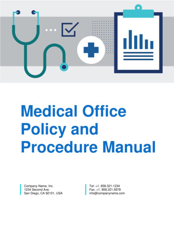
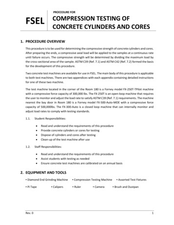
Gage Descriptions Gage type is determined by magnetic propertiesemployed to measure thickness (not the read-outmode) Type 1 – Magnetic Pull-off Gages Type 2 – Electronic Gages
Gage TypesType 1 – Magnetic Pull-offGagesType 2 – Electronic Gages
Gage Types, continued Type 1 – Magnetic Pulloff Gages Permanent magnetcontacts coated surface Force required todetach magnet ismeasured Force interpreted as thecoating thickness onscale or display Scale is nonlinear
Gage Types, continued Type 2 – ElectronicGages Electronic circuitryconverts reference signalto coating thickness
Calibration & Verification ofAccuracy ASTM D7091 describes 3 operational steps toensure accurate measurement: Calibration Verification of Accuracy Adjustment Steps are required to be completed beforecoating thickness data acquisition to determineconformance to a specification
Gage Calibration Performed by the gage manufacturer or anaccredited calibration laboratory Test certificate traceable to a NationalMetrology institution required No standard calibration interval (establishedbased on experience & work environment) One year interval is common
Verification of Type 1 Gage Accuracy Performed as described inASTM D7091 Beginning and end of each work shift(minimum) During (e.g., hourly), if: Obtaining a large no. of readings Gage is dropped or readings aresuspect Record: Serial no. of gage & standard Stated & measured thickness Method used to verify accuracy
Verification of Type 1 Gage Accuracy Type 1 gages should not be “adjusted” Adjustments to the helical spring may void thegage warranty Combined tolerance of gage and coatedstandard determines gage accuracy E.g., if gage accuracy is 5% and reference standardaccuracy is 3%, combined tolerance is 6%,calculated as: 52 32 On a 10 mil reference standard, the gage readingcan range from 9.4-10.6 mils
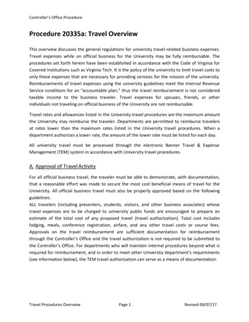
Correction for Surface Roughness Base Metal Reading (BMR) Effect of surface roughnesson coating thickness gage NOT surface profile Measure the prepared,uncoated substrate; calculateaverage BMR Deduct BMR frommeasured coating thicknessBMR
Correction for SurfaceRoughnessAreaBMR130 µm (1.2 mils)225 µm (1.0 mils)318 µm (0.7 mil)413 µm (0.5 mil)520 µm (0.8 mil)68 µm (0.3 mil)725 µm (1.0 mil)828 µm (1.1 mils)923 µm (0.9 mil)1013 µm (0.5 mil)Measuring Base Metal Effect with Type 1DFT GageAverage BMR: 21 µm (0.8 mil)
BMR Correction for Multiple CoatSystemsMeasured Primer Thickness:BMR:Actual Primer Thickness:102 µm (4.0 mils)13 µm (0.5 mils)89 µm (3.5 mils)Measured Primer Finish Thickness:BMR:Actual Total System Thickness:178 µm (7.0 mils)13 µm (0.5 mils)165 µm (6.5 mils)
Correction for Surface Roughness What if access to blast cleaned steel is notavailable (already coated)? Appendix A8.3 addresses smooth surfaceadjustment Verify gage accuracy on a smooth surface (pergage manufacturer instructions) Deduct “assumed” approximate correction valuefrom each gage reading
Correction for Surface RoughnessTable A8Typical Gage Correction Values UsingISO 8503 Profile GradesISO 8503 ProfileGradeCorrection Value(µm)Correction value(mils)Fine100.4Medium251.0Coarse401.6
Verification of Type 2 Gage Accuracy Verify accuracy permanufacturer instructions(use coated standards) Performed as described inASTM D7091 Beginning and end of each workshift (minimum) During (e.g., hourly), if: Obtaining a large no. of readings Gage is dropped or readings aresuspect Record: Serial no. of gage & standard Stated & measured thickness
Verification of Type 2 Gage Accuracy Single Point Verification Select one reference coated standard representing themid-range of the anticipated coating thickness E.g., 4-6 mils (100-150 µm), select 5 mil (125 µm)reference standard Tw0 Point Verification Select reference coated standards below and above themedian anticipated coating thickness E.g., 5 mils (125 µm), select 3 mil (75 µm) and 7 mil(175 µm) coated standards
Adjustment of Type 2 Gages Aligning a gage’s thicknessreadings to those of a knownthickness value to improve gageaccuracy on a specific surface orwithin a measuring range Corrects for: Surface RoughnessSubstrate Properties (metallurgy)CurvatureEtc. Use Certified or Measured shims
Adjustment of Type 2 Gages Addressed in Appendix 8 Follow the gagemanufacturers step-by-stepprocedures for gageadjustment Instructions vary by gagemanufacturer Adjustment is performedusing certified or measuredplastic shims (foils)
Measurement Frequency
Measurement Frequency For areas of coating not exceeding 300 square feet,( 30 square meters) each 100 square feet ( 10 squaremeters) is measured For areas of coating exceeding 300 square feet andnot exceeding 1000 square feet, arbitrarily select 3random 100 square foot ( 10 square meter) areas andmeasure
Measurement Frequency For areas of coating exceeding 1000 square feet( 100 square meters), arbitrarily select 3 - 100 squarefeet ( 10 square meter) areas for the first 1000 squarefeet ( 100 square meters), and 1 additional 100square foot( 10 square meter) area for eachadditional 1000 square feet (100 square meters), orportion thereof
Measurement Frequency
Measurement Frequency Example 1(US Standard)Size of Coated Area:900 square feetNo. of Areas:No. of Spots:3 areas3 Areas x 5 Spots/Area 15SpotsMinimum No. of GageReadings:15 Spots x 3 Readings/Spot 45 Gage Readings
Measurement Frequency Example 2(US Standard)Size of Coated Area : 12,500 square feetNo. of Areas:No. of Spots:Minimum No. of GageReadings:3 12 15 areas15 Areas x 5 Spots/Area 75Spots75 Spots x 3 Readings/Spot 225 Gage Readings
Conformance to SpecifiedCoating Thickness Specifications normally indicate therange of coating thickness (e.g., 5-7mils), not as a single value (e.g., 5mils) When a single thickness value isspecified and no range is indicatedby manufacturer: Range established at /-20% of statedthickness value E.g., 7 mils is 5.6-8.4 mils
Table 1Coating Thickness Restriction LevelsThicknessGage ReadingSpotReadingArea MeasurementLevel 1MinimumUnrestrictedAs specifiedAs specifiedMaximumUnrestrictedAs specifiedAs specifiedMinimumUnrestrictedAs specifiedAs specifiedMaximumUnrestricted120% of maximumAs specifiedMinimumUnrestricted80% of minimumAs specifiedMaximumUnrestricted120% of maximumAs specifiedMinimumUnrestricted80% of minimumAs specifiedMaximumUnrestricted150% of maximumAs specifiedMinimumUnrestricted80% of minimumAs edLevel 2Level 3Level 4Level 5Note: If unspecified, Level 3 is the default
Measurement ToleranceEXAMPLE 1: Target DFT: 4-6 mils Coating Thickness Restriction Level 3 (default) Individual gage readings unrestricted Spot measurements must be between 3.2 mils and 7.2 mils Area measurement must be between 4 and 6 mils If spot or area measurements are out of tolerance, themagnitude of the nonconforming thickness must be determinedand demarcated.
Measurement ToleranceEXAMPLE 2: Target DFT: 4-6 mils Coating Thickness Restriction Level 2 Individual gage readings unrestricted Spot measurements must be between 4 mils and 7.2 mils Area measurement must be between 4 and 6 mils If spot or area measurements are out of tolerance, themagnitude of the nonconforming thickness must be determinedand demarcated.
SSPC-PA 2 Measurement SpecificationsBuilt Into Type 2 GagesAudible and/or visualindicators if spot readings areout of tolerance
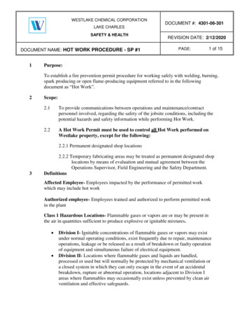
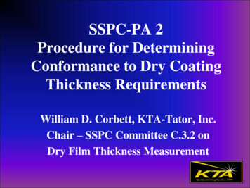
Determining the Magnitude of aNonconforming Area Obtain spot measurements at 5 foot intervals in 8 equallyspaced directions radiating out from the nonconforming areaup to the limit of area coated during the work shift Each spot must conform to requirements When 2 consecutive spots conform to requirements,measuring can stop Area within 5 feet of any nonconforming measurement issuspect and must be re-inspected after correction Repeating structural units or parts – 1 spot measurement oneach unit Repeat until spot readings on 2 consecutive units conform
Dashed line indicates boundary of area painted during work shiftOKSTOPSTOPOKSTOP5 ftNOOKSTOP OKOKOKOK5 ftSuspect areapreceding anonconformingspot must be remeasured aftercorrections aremadeNOOK5 ftSTOP(Limit ofareacoatedduringwork shift)OKSTOPDashed line indicates boundary of area painted during work shift(Limit ofareacoatedduringwork shift)OK(Limit ofareacoatedduringwork shift)STOPDashed line indicates boundary of area painted during work shiftOK5 ftDashed line indicates boundary of area painted during work shiftOK
SSPC-PA 2 Appendices1. Numerical Example of Average ThicknessMeasurement2. Methods for Measuring DFT on Steel Beams(Girders)3. Methods for Measuring DFT for a Laydownof Beams, Structural Steel & Misc. Parts afterShop Cleaning4. Method for Measuring DFT on Coated SteelTest Panels
SSPC-PA 2 Appendices, cont.5. Method for Measuring the DFT of ThinCoatings on Coated Steel Test Panels thatHave Been Abrasive Blast Cleaned6. Method for Measuring the DFT of Coatingson Edges7. Method for Measuring the DFT of CoatedSteel Pipe Exterior8. Examples of the Adjustment of Type 2 GagesUsing Shims
Appendix 2: Measuring CoatingThickness on Steel Beams (Girders) Full Determination Sample Determination Beams 20 ft ( 6 m) Beams 20 ft - 60 ft (6 m-18 m) Beams 60 ft ( 18 m) Coating Thickness RestrictionLevel 3 (default) The average of all spotmeasurements (per area) mustconform to specified range Measurement locations onstiffeners arbitrarily selectedStiffener
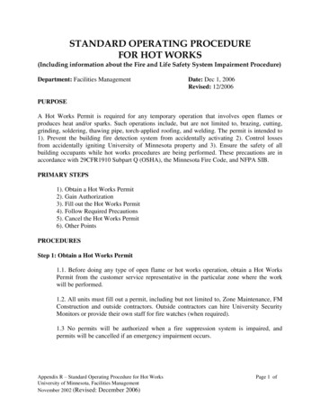
Appendix 2: Measuring CoatingThickness on Steel Beams (Girders) Full Determination Divide beam into 5 equalsections along the length Web 36”: Obtain one spotmeasurement in 14 areas, persection (total of 70 spotmeasurements) Web 36”: Obtain one spotmeasurement in 12 areas, persection (total of 60 spotmeasurements)
Full DeterminationNote: Areas 2, 6, 8 and 12 (Toe) may not be measured.The top of the top flange may not be accessible
Appendix 2: Measuring CoatingThickness on Steel Beams (Girders) Sample Determination Beam length 20 ft: Obtain 2spot measurements randomlydistributed in all 12 areas (totalof 24 spot measurements) Beam length 20-60 ft: Obtain 3spot measurements randomlydistributed in all 12 areas (totalof 36 spot measurements)Note: If toe areas are notincluded, measure in 8 areas(16 or 24 spot measurements)
Appendix 3: Measuring CoatingThickness on Laydown of Beams Laydown: Group of steelmembers laid down to bepainted in one shift by oneapplicator Full DFT Determination Beams (girders) Miscellaneous parts Sample DFT Determination Beams 20 ft (6 m) Beams 20 ft - 60 ft (6 m-18 m)
Appendix 4: Measuring CoatingThickness on Test Panels Minimum panel size:3” x 6” (7.5 x 15 cm) Maximum panel size:12” x 12” (30 x 30 cm) Use Type 2 gage Two gage readings from top,middle and bottom third At least 0.5” from edge and1” from other readings 80% min. & 120% max.applies to gage readings135246
Appendix 5: Measuring Thickness of ThinCoatings on Abrasive Blast Cleaned TestPanels “Thin” is considered 1 mil(25.4 µm) or less Obtain 10 gage readingsfrom each of three “zones” Calculate the mean andstandard deviation in eachzone The mean of all threezones is the
SSPC-PA 2 Appendices, cont. 5. Method for Measuring the DFT of Thin Coatings on Coated Steel Test Panels that Have Been Abrasive Blast Cleaned 6. Method for Measuring the DFT of Coatings on Edges 7. Method for Measuring the DFT of Coated Steel Pipe Exterior 8. Examples of the Adjustment of Type 2 Gages Using Shims . Appendix 2: Measuring Coating Thickness on Steel Beams (Girders) Full .