Transcription
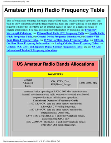
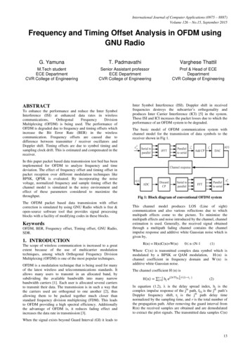
International Journal of Computer Applications (0975 – 8887)Volume 126 – No.15, September 2015Frequency and Timing Offset Analysis in OFDM usingGNU RadioG. YamunaT. PadmavathiVarghese ThattilM.Tech studentECE DepartmentCVR College of EngineeringSenior Assistant professorECE DepartmentCVR College of EngineeringProf & Head of ECEDepartmentCVR College of EngineeringABSTRACTTo enhance the performance and reduce the Inter SymbolInterference (ISI) at enhanced data rates in Multiplexing (OFDM) is being used. The performance ofOFDM is degraded due to frequency and timing offsets whichincrease the Bit Error Rate (BER) in the wirelesscommunication. Frequency offsets are caused due todifference between transmitter / receiver oscillators andDoppler shift. Timing offsets are due to symbol timing andsampling clock drift. This is estimated and compensated in thereceiver.In this paper packet based data transmission test bed has beenimplemented for OFDM to analyze frequency and timedeviation. The effect of frequency offset and timing offset inpacket reception over different modulation techniques likeBPSK, QPSK is evaluated. By incorporating the noisevoltage, normalized frequency and sample timing offset thechannel model is simulated in the noisy environment andeffect of these parameters considered to maximize thethroughput.The OFDM packet based data transmission with offsetcorrection is simulated by using GNU Radio which is free &open-source software tool that provides signal processingblocks with a facility of modifying codes in these blocks.KeywordsOFDM, BER, Frequency offset, Timing offset, GNU Radio,SDR.1. INTRODUCTIONThe scope of wireless communication is increased to a greatextent because of the use of multicarrier modulationtechniques, among which Orthogonal Frequency DivisionMultiplexing (OFDM) is one of the most popular techniques.OFDM is a modulation technique that is being used for manyof the latest wireless and telecommunications standards. Itallows many users to transmit in an allocated band, bysubdividing the available bandwidth into many narrowbandwidth carriers [1]. Each user is allocated several carriersto transmit their data. The transmission is in such a way thatthe carriers used are orthogonal to one another [2], thusallowing them to be packed together much closer thanstandard frequency division multiplexing (FDM). This leadsto OFDM providing a high spectral efficiency. Additionallythe advantage of OFDM is, it reduces fading effect andincreases the data rate in transmission [3].Inter Symbol Interference (ISI). Doppler shift in receivedfrequencies destroys the subcarrier’s orthogonality andproduces Inter Carrier Interference (ICI) [5] in the system.These ISI and ICI increases the packet losses due to which theperformance of an OFDM system to be degraded.The basic model of OFDM communication system withchannel model for the transmission of data symbols to thereceiver shown in Fig 1.Fig 1: Block diagram of conventional OFDM systemThis channel model produces LOS (Line of sight)communication and also various reflections due to whichmultipath effects come to the picture. To minimize themultipath effects and noise introduced by the channel, channelestimation is used. Generally, the received signal obtainedthrough a multipath fading channel contains the channelimpulse response and additive white Gaussian noise which isgiven by,0 n N-1R(n) H(n)C(n) W(n)(1)Where C(n) is transmitted complex data symbol which ismodulated by a BPSK or QAM modulation, H (n) ischannel coefficient in frequency domain and W (n) isadditive white Gaussian noise.The channel coefficient H (n) isH n r 1j 0 hjnej2πTf Dj N (λ τj)(2)In equation (1.2), λ is the delay spread index, h j is thecomplex impulse response of the jth path, fDj is the jth path’sDoppler frequency shift, τj is the jth path delay timenormalized by the sampling time, and r is the total number ofthe propagation path. After removing the guard interval fromR(n) the received samples are obtained and are demodulatedto extract the pilot signals. The transmitted data samples C(n)When the signal exists beyond Guard Interval (GI) it leads to13
can be recovered by simply dividing the received signal by thechannel response,Y n R(n)H(n)(3)1.1 Effect of Offsets and ChannelEstimationThe performance degradation in OFDM is due to frequencyoffset and Timing offset. Frequency offset is defined as thedifference between the nominal frequency and actual outputfrequency. It occur due to a difference in the frequencies ofthe local oscillators in the transmitter and receiver, gives riseto a shift in the frequency domain which is also referred to asfrequency offset [4, 5]. This offset can also be caused due tothe Doppler shift in the channel. Timing offset is occurringdue to different rates between the sample clocks of thetransmitter and receiver. It also occurs due to changes insymbol timing. The demodulation of a signal with theseoffsets can cause large BER and may degrade the performanceof a symbol synchronizer. It is therefore important to estimatethe frequency offset and minimize its impact. These offsetscan be estimated and corrected by using channel estimatorfollowed by equalizer.Channel estimation is the process of analyzing / characterizingthe effect of the physical medium on the transmitted data.International Journal of Computer Applications (0975 – 8887)Volume 126 – No.15, September 2015delay spread 25% of total subcarriers are allocated for cyclicprefix (CP). Along with CP, preamble is used for detectionand synchronization and initial channel state information(CSI).After modulation the entire parallel data converted into serialform and then transmitted through the AWGN channel model.In the testbed normalized frequency and sample timing offsetsare incorporated.In this testbed data aided channel estimation technique isused. It can be implemented in couple of ways namely blocktype and comb type. The block type channel estimation isdone through training symbols (sending known informationover one or more whole OFDM symbols without anydata), and in comb type pilots aided channel estimation(sending known information together with the data). Blocktype suits more for slow-fading channels and comb type isused for fast fading channels.At the receiver side preamble is used to detect the framestarting time and offset which occur due to multipath by usingSchmidl & Cox technique [10]. It uses two training symbolswith special pattern. With the help of first symbol it produce atrigger signal to find the frame starting time. The time domainpreamble proposed by Schmidl & Cox technique isPreamble p [PN PN ]2The channel estimation techniques are of two types, Blindchannel estimation techniques and Data-aided channelestimation techniques. The first technique is used to estimatethe channel state information (CSI) without the knowledge ofthe transmitted signal and the second estimation technique isto estimate the channel response by the known informationadded to the transmitted signals.Where, PN/2 represents samples of length N/2. The timingmetric of Schmidl & Cox is given asM d Reconfigurability is a key feature with all software-definedradio systems [9]. Instead of using different radios designedfor specific but different purposes, a single general-purposeradio can be used as the radio front-end, and the signalprocessing software (here GNU Radio) handles the processingspecific to the radio application.2. OFDM IMPLEMENTATIONThe implementation of OFDM communication system includetransmitter, receiver and channel model. The functionality ofthe OFDM communication system is verified with suitableSDR blocks shown in Fig 2.In the transmitter the data or message signal is generated withthe help of Galois linear feedback shift register (GLFSR)source. From GLFSR source Pseudo random sequence (PRC)data is encapsulated and is modified in to packet by includingpreamble and header. This packet is transmitted with the 64orthogonal subcarriers. These are modulated using amodulation schemes like BPSK, QPSK etc. In this test bedBPSK modulation is used to transmit header because of itslow Bit Error Rate (BER) and QPSK is used for payload.Among 64 subcarriers, 48 subcarriers are used for data, 4subcarriers are used to carry pilot symbols. To avoid ISI andP(d)2(5)(R d )2Where,1.2 GNU Radio CompanionGNU Radio is a free software development toolkit [6, 7] .Itprovides signal processing blocks to implement softwaredefined radios (SDR) [8, 9] and signal processing systems. Itcan be used with external RF hardware to create SDRs orwithout hardware in a simulation environment. It is widelyused in academic and commercial environments to supportboth wireless communications research and real-world radiosystems [7].(4)2P d R d 𝑁 12𝑘 0 𝑟 𝑁 12𝑘 0𝑁𝑑 𝑘 . 𝑟(𝑑 𝑘 )2𝑁𝑟(𝑑 𝑘 )2(6)2(7)The starting point of symbol is given by the maximum oftiming metric M (d). The timing metric of Schmidl & Cox hasa large plateau and has its peak for entire interval of CP.Frequency offset can also be calculated and corrected with theSchmidl & Cox technique [10]. The trigger signal along withreceived data is send to header and payload Demultiplexer(HPD) block. The HPD block copies the header and preambleinformation to its first output. The header data is demodulatedto identify the packet number and payload length andfeedback to the HPD block. Based on this information HPDcopies the payload to its second output and it alsodemodulated. From the preambles and pilot sequences thechannel estimation calculates the frequency offset with theSchmidl & Cox technique. The calculated frequency Offsetsis corrected in the serial equalizer block.Serializer plucks the data symbols from the occupiedcarriers and outputs them as a stream of complex scalars.Constellation decoder decodes constellation's points from acomplex space to (unpacked) bits based on the map ofthe constellation object. Payload demodulation follows thesame procedure as header demodulation except channelestimation block.14
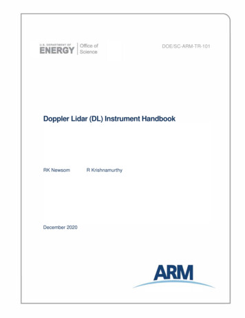
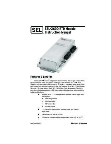
International Journal of Computer Applications (0975 – 8887)Volume 126 – No.15, September 2015Fig 2: Block diagram of OFDM system3. EXPERIMENTAL RESULTSThe required parameters and specifications for OFDMtransmitter are defined in Table 1. The IFFT/FFT size is 64and cyclic prefix is ¼th of the IFFT/FFT size (FFT size 64and CP length 16 (1/4th of 64)). The cyclic prefix reduces theproblem caused due to delay spread and maintains continuityof the signal which ensures orthogonal reception of receivedsignal subcarriers.Table 1: Experimental ParametersParametersSpecificationsFFT Size64Occupied tones52Cyclic prefix16Sampling Rate10MModulation techniqueBPSK, QPSKSub carrier spacing156.25 KHzSystem ChannelBandwidth8 MHzFig 3: Frequency domain format of input signalIn this testbed 64 orthogonal carriers are used to modulate thedata. The resultant time domain representation of OFDMsignal is shown in Fig 4.The GLFSR source generates the input data with polynomialdegree of 2, with peak to peak amplitude of 1 to -1 which isshown in Fig 3.Fig 4: Time domain representation of OFDM signalThe functionality of OFDM Transmission and reception isverified by observing the demodulated signal at the output ofreceiver.The frequency domain representation of both signalsare displayed in Fig 5.15
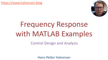
International Journal of Computer Applications (0975 – 8887)Volume 126 – No.15, September 2015The above figure 6 indicates maximum number of packets canbe received at lower offset levels. Packets receivedsuccessfully until the frequency offset level of 14.0625 Hz. Ifthe offset is higher than 14.0625 Hz packet losses occurred.However this loss can be controlled to certain extent with thehelp of Channel Estimator block in this testbed andthroughput is maximized.3.1 Performance of Channel EstimationFig 5: Frequency domain representation of transmittedand received signals3.1. Effect of Frequency Offset in PacketReceptionThe channel model used in this testbed allows the user toincorporate the noise voltage, a normalized frequency offsetand a sample timing offset of AWGN source. By using theseparameters the OFDM testbed is simulated in noisyenvironment. The effect of these parameters in packetreception can be shown in table 2 by varying these offsetsslowly.An increase of offset in the channel model causes loss ofpackets. Due to this frequency offset resulting throughput isless even for 50 packets without any channel estimation. Withthe help of frequency offset parameter in channel model theoffset is inserted in the carrier slowly and the effect of thisoffset is observed in the packet reception as shown in table 2.Sub carrier spacing used in this test bed is 156.25 KHz.Table 2: Effect of Frequency Offset in Packet ReceptionFrequency Offset (Hz)Number of Packets lostduring Transmission0 (no offset)Nil3.90625Nil11.7188Nil14.0625Nil15.625Loss in 28 packetsBy including OFDM Channel Estimation in the OFDMsystem the coarse frequency offset correction has been donewith the help of Equalizer. The max carrier offset parameterset at 3 (means offset 3 is shared by 64 carriers, each carrierget 46.8 Hz offset). If the offset occur in channel for eachcarrier is smaller than 46.8 Hz, packets may receivesuccessfully. If it is greater than 46.8 Hz packet loss mayoccur. It is observed by keeping max carrier offset at 3 i.e.constant and the frequency offset parameter in channel modelis varied. It can also be verified with max carrier offsetparameter set at 5 (means offset 5 is shared by 64 carriers,each carrier get 78.12 Hz offset). If the offset occur in channelfor each carrier is smaller than 78.12 Hz, packets may receivesuccessfully. If it is greater than 78.12 Hz packet loss mayoccur. It is observed by keeping max carrier offset at 5 i.e.constant and the frequency offset parameter in channel modelis varied.The effect of Frequency Offset in Packet Reception withChannel Estimation is shown in table 3.Table 3: The effect of Frequency Offset in PacketReception with Channel EstimationMax carrier offset at 3FrequencyOffset (Hz)Number ofPackets lostduringTransmissionFrequencyOffset(Hz)Number ofPackets l39.0625NilLoss in 22packetsLoss in 37packetsLoss in 47packets54.6875Nil62.5NilAll78.156215.6406Loss in 35 packets15.6562Loss in 45 packets46.87515.6719All46.8906The effect of frequency offset in packet reception is shown inFig 6.Max carrier offset at 546.906246.921978.12578.140625 packetsare lost39 packetsare lost48 packetsare lostThe effect of frequency offset in packet reception is shown inFig 7 and 8.Fig 6: Effect of Frequency Offset in Packet Reception16
International Journal of Computer Applications (0975 – 8887)Volume 126 – No.15, September 2015Table 4: Effect of Timing Offset in Packet ReceptionTiming OffsetFig 7: Effect of Frequency Offset in Packet Receptionwith Channel Estimation.1Number of Packets lostduring TransmissionNil1.001Nil1.002Nil1.00226 packets loss1.002318 packets loss1.002427 packets loss1.002541 packets lossTiming offset at the level 1 indicates that there is nodifference between sample clocks of the transmitter andreceiver. It is observed that if the difference is above the levelof 1.002 loss of packets occur. The study has been carried outat CP 16 (25% of FFT size). The effect of Timing offset inpacket reception is shown in figure 10.Fig 8: Effect of Frequency Offset in Packet Receptionwith Channel Estimation.From the Fig 6, 7 and 8, it is verified that the packets can bereceived successfully even at higher offsets with the help ofChannel Estimation. Packets are received successfully untilthe carriers getting offset of 39.0625 Hz when the max carrieroffset at each carrier is 46.8 Hz. If the max carrier offset ateach carrier is78.12 Hz packets received successfully untileach carrier has an offset of 62.5 Hz.Packet loss in OFDM system with and without channelestimation is observed and correspondingly plots are drawn.The Fig 9 shows that the packet loss with channel estimationis lesser when compared to one without channel estimation.Fig 10: Effect of Timing Offset in Packet ReceptionCarrier alignment used in the packet structure is total of 64carriers among that positive carriers 1 to 26 and negativecarriers -1 to -26 carrying data and remaining carriers alongwith dc carrier does not carry any data to reduce the out ofband radiation as shown below.Tag Debug: Rx BytesInput Stream: 00Fig 9: Comparison between with & without channelestimation in terms of successful packet reception.3.2 Effect of Jitter (Timing Offset) inPacket ReceptionAlong with the frequency offset the effect of timing offset inpacket reception has verified as shown in table 4. It indicatesthat an exponential rise in offset leads the loss of packet. Inthis testbed with the help of epsilon parameter in channelmodel increase the timing offset and verified this effect onpacket reception is shown in table 4.Offset: 0 Source: n/a Key: ofdm sync chan taps Value:#[(0,0) (0,0) (0,0) (0,0) (0,0) (0,0) (-61.2248,19.2573) (41.9073,48.8774) (-7.04559,63.2687) (30.0647,55.6706)(57.7198,30.0126) (63.1257,-11.4095) (49.1463,-40.9515)(17.8219,-60.9554) (-19.0174,-59.8843) (-49.9789,-40.6941)(-64.417,-5.63722) (-57.8558,30.182) (-29.5168,57.0675)(7.09093,64.4349) (41.0565,49.4044) (61.8325,17.9921)(60.1552,-18.4434) (4.23578,-5.28534) (0.64715,-6.47385) (34.4013,-53.0797) (-6.88902,-2.56118) (-7.41967,1.53169) (5.1245,3.9951) (0,0) (6.14543,-3.82864) (3.53023,-6.4351) (1.04827,-7.01485) (-4.24902,-5.65356) (-6.66226,-2.49364) (6.56885,2.05846) (-36.2451,53.0564) (-0.77507,7.85118)(3.14919,5.95864) (6.06372,3.97592) (6.41652,-0.757187)(5.79803,-5.13304) (1.29741,-7.46136) (-2.58211,-6.87754) (6.26773,-4.02898) (-6.99886,-0.856864) (-6.49312,3.2603) 4)(1.81976,-7.58057) (-3.44643,-6.41928) (-6.17859,-4.1949)(0,0) (0,0) (0,0) (0,0) (0,0)]Offset: 0 Source: n/a Key: packet num Value: 017
International Journal of Computer Applications (0975 – 8887)Volume 126 – No.15, September 2015Offset: 0 Source: n/a Key: ofdm sync carr offset Value: 0Offset: 0 Source: n/a Key: packet len Value: 964. CONCLUSIONIn this paper packet based, OFDM testbed is implementedusing GNU platform and the performance of OFDM systemis evaluated in the simulation environment. All the blocksof OFDM have been thoroughly investigated by givingdifferent parameters as inputs.The effect of frequency and timing offsets in packet receptionis observed by varying these offset levels in channel model.The simulation results show that increase in offset causesincreases in BER which leads loss of packets. The frequencyoffset error is detected and corrected with the help of Schmidl& Cox technique, channel estimation and equalizationtechniques respectively and throughput is maximized. Thesesimulation results show that OFDM channel estimation usingSchmidl & Cox Technique is effective till the stage ofhardware/ spectrum limitations.The development of the OFDM testbed with SDR opensvarious opportunities to research further advanced signalprocessing techniques for OFDM based systems, such as theimproved synchronization and channel estimation techniques,the techniques to reduce the well known Peak-to-AveragePower Ratio (PAPR) issue, and the emerging Multiple-InputMultiple-Output (MIMO) technique. To make use of theOFDM channel estimation testbed in real time using USRP,can be extended as future work to observe the bit error rate(BER). This can also verified by using different modulationschemes such as QPSK, QAM, 8 QAM, instead of BPSK andBER can also be reduced with suitable synchronizationschemes.5. REFERENCES[1] Nicola Marchetti, Muhammad Imadur Rahman, SanjayKumar and Ramjee Prasad “OFDM: Principles andChallenges”IJCATM : www.ijcaonline.org[2] com/2008/02/03/understanding- anofdm transmission/[3] Manushree Bhardwaj, Arun Gangwar, Devendra Soni“A Review on OFDM: Concept, Scope & itsApplications” IOSR Journal of Mechanical and CivilEngineering(IOSRJMCE)ISSN:2278-1684Volume 1, Issue 1 (May-June 2012), PP 07-11www.iosrjournals.org.[4] Mourad MELLITI , Salem HASNAOUI , RidhaBOUALLEGUE , “Analysis of Frequency Offsets andPhase Noise Effects on an OFDM 802.11 gTransceiver”, ( )SYSCOM Laboratory, National Schoolof Engineering of Tunis TUNISIA ( )SYSTELLaboratory SUP’COM, National School of Engineeringof Sousse TUNISIA IJCSNS VOL.7 No.4, April 2007.[5] Inter Carrier Interference (ICI) in OFDM due effect-of-ici-inofdm/[6] Ke-Yu, Chen (8818-0493), Zhi-Feng Chen (12181197), “GNU Radio” Dept. of Electrical ComputerEngineering University of Florida, Gainesville, Florida.[7] WhatIsGR & what exactly does GNU Radio do iki/WhatIsGR[8]“What is Software Defined Radio –Wireless InnovationForm”from www.wirelessinnovation.org/what is sdr.[9] Carlos E. Caicedo, Ph.D. Student. Software DefinedRadio and Software Radio Technology: ConceptsandApplication. Department of Information Science andTelecommunications University of Pittsburgh.[10] T. M. Schmidl, and D. C. Cox, “Robust frequency andtiming synchronization for OFDM,” IEEE Trans.Comm.45, 1613-1621 (1997).18
Schmidl & Cox technique [10]. The trigger signal along with received data is send to header and payload Demultiplexer (HPD) block. The HPD block copies the header and preamble information to its first output. The header data is demodulated to identify the packet number and payload length and feedback to the HPD block.