Transcription
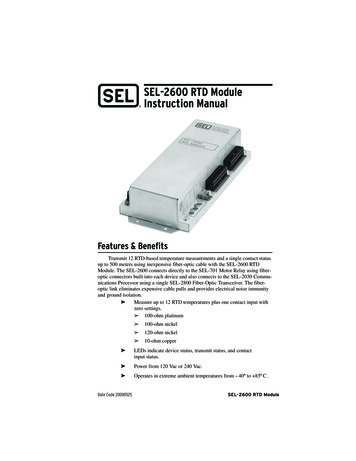
SEL-2600 RTD ModuleInstruction ManualFeatures & BenefitsTransmit 12 RTD-based temperature measurements and a single contact statusup to 500 meters using inexpensive fiber-optic cable with the SEL-2600 RTDModule. The SEL-2600 connects directly to the SEL-701 Motor Relay using fiberoptic connectors built into each device and also connects to the SEL-2030 Communications Processor using a single SEL-2800 Fiber-Optic Transceiver. The fiberoptic link eliminates expensive cable pulls and provides electrical noise immunityand ground isolation. Measure up to 12 RTD temperatures plus one contact input withzero settings. 100-ohm platinum 100-ohm nickel 120-ohm nickel 10-ohm copper LEDs indicate device status, transmit status, and contactinput status. Power from 120 Vac or 240 Vac. Operates in extreme ambient temperatures from – 40º to 85º C .Date Code 20000525SEL-2600 RTD Module
2Initial CheckoutInitial CheckoutStep 1.Connect Terminal 26 to an appropriate ground.Step 2.Apply line power to the SEL-2600 at Terminals 23 and 24(120 Vac) or Terminals 23 and 25 (240 Vac).The SEL-2600 will power up and perform internal diagnostics.The module is ready when the green ENABLE LED illuminates.Step 3.Verify the red TX LED pulses twice per second. Each pulsecorresponds to the transmission of RTD data, device status, andcontact input status.Step 4.Connect Terminal 20 to Terminal 21 to test the contact input. Thered INPUT LED illuminates when the contact input is electricallyshorted.Step 5.SEL-701 Motor Relay Application Connect the SEL-2600 to the SEL-701 Motor Relay asshown in Figure 1 on page 4. Set the relay as directed inSEL-701 Motor Relay Application on page 4.NOTE: The SEL-701 front panel may display “RTD Failure” if the correct RTDs are notyet connected. The SEL-701 METER T report displays the RTD temperature as“Comm Fail” if the fiber connection is not operating properly.SEL-2030 Communications Processor Application Step 6.Connect the SEL-2600 to the SEL-2030 CommunicationsProcessor as shown in Figure 2, Figure 3, or Figure 4 onpage 7. Set the SEL-2030 as directed in SEL-2030 Communications Processor Applications on page 6.Follow the wiring diagram in Figure 5 on page 13 to connectRTDs to the SEL-2600.NOTE: If RTDs are not available, test the SEL-2600 RTD inputs by connecting allthree terminals for each RTD together. For example, using two short wires, connect Terminals 01, 02, and 03 together. The SEL-701 METER T report displays thecorresponding temperature as “Short.” The SEL-2030 stores the hexidecimalvalue 8000h in the corresponding data register.SEL-2600 RTD ModuleDate Code 20000525
Installation3InstallationStep 1.Locate an appropriate mounting panel or enclosure near theprotected device.Step 2.Drill four mounting holes (see Figure 6 on page 14).Step 3.Secure the SEL-2600 using the four bolts and locknuts provided.Step 4.Ground the SEL-2600 by connecting Terminal 26 to anappropriate electrical ground.Step 5.Connect as many as 12 RTDs to the SEL-2600 terminal blocks(see Figure 5 on page 13).Step 6.Record the type and location of each RTD in Table 1 on page 4.Step 7.Connect a dry contact to the SEL-2600 contact input Terminals 20and 21 as appropriate.!Step 8.CAUTION: Do not connect ac or dc voltage to the contact input.SEL-701 Motor Relay Application Connect the SEL-2600 to the SEL-701 Motor Relay using asingle fiber-optic cable (SEL part number C801FZ orC801FD). Follow the SEL-701 setting instructions inSEL-701 Motor Relay Application on page 4.SEL-2030 Communications Processor Application Connect the SEL-2600 to the SEL-2030 CommunicationsProcessor using a single fiber-optic cable and a fiber-optictransceiver as outlined in SEL-2030 Communications Processor Applications on page 6.Step 9.Step 10.Date Code 20000525Connect ac line power to the SEL-2600 through Terminals 23 and24 (120 Vac) or Terminals 23 and 25 (250 Vac). The greenENABLE LED illuminates when ac power is applied and theinternal diagnostics are complete.Verify the SEL-2600 is operating properly. The green ENABLE LED is illuminated. The red TX LED pulses twice per second. The red INPUT LED illuminates when the SEL-2600 contactinput is energized. The SEL-701 or SEL-2030 receives valid RTD measurements.SEL-2600 RTD Module
4SEL-701 Motor Relay ApplicationTable 1RTD Type and Location Worksheet.Table 1RTD Type and Location WorksheetRTD InputRTD LocationRTD RTD12SEL-701 Motor Relay ApplicationThe SEL-701 Motor Relay provides comprehensive motor protection, including short circuit, load loss, load jam, and frequent starting protection as well asunbalance current and phase reversal protection. The patented motor thermal protection element used by the SEL-701 Motor Relay accurately tracks the heatingeffects of overloads and unbalance current.Combining the SEL-2600 and the SEL-701 Motor Relay enhances this list ofprotection features by adding remote RTD-based thermal protection.Up to 12 RTD inputs, plusone contact (speed switch, etc.)Fiber-Optic Ports(built into SEL-2600 & SEL-701)SEL-2600MotorFigure 1LoadSEL-701RelayUp to 500 meters viasingle fiber-optic cable,SEL part number C801FDMotor Protection with the SEL-701 Motor Relay.SEL-2600 RTD ModuleDate Code 20000525
SEL-701 Motor Relay ApplicationStep 1.Connect the SEL-2600 to the SEL-701 Motor Relay using fiberoptic cable C801FD. Connect the cable between the SEL-2600Fiber-Optic TX output and the SEL-701 Motor Relay Fiber-OpticRX input.Step 2.Set the SEL-701 Motor Relay to accept the RTD temperature datapackets (see Data Packet Definition on page 11) sent by theSEL-2600. You can use any of the following three methods toenter the settings. Relay front-panel menus: Set Relay\Relay Elements\RTDCONFIGURATION. Personal computer connected to the relay serial port, runningSEL-701PC software. Personal computer connected to the relay serial port, using aterminal emulation software package.5In the SEL-701 Relay, set the RTD Input Option setting(RTDOPT) equal to EXT. This enables use of the external moduledata. Set the RTD Location and RTD Type settings based on theinformation you recorded in Table 1 on page 4. Finally, set theRTD Alarm and Trip Temperature settings as required for yourapplication.Refer to the SEL-701 Motor Relay Instruction Manual for moredetails regarding calculation and entry of these settings.Step 3.After accepting the relay settings, verify correct RTD temperaturemeasurement using one of these methods. Relay front-panel menus: Meter Values\Thermal & RTDData. Personal computer connected to the relay serial port, runningSEL-701PC software. Personal computer connected to the relay serial port, using aterminal emulation software package and the METER Tcommand.The relay will indicate the temperatures of each connected,healthy RTD. If the relay reports that an RTD is open or shorted,or if the temperature reading is wrong, verify the wiring at theSEL-2600. Also verify the RTD type connected to that inputmatches the RTD type setting.Date Code 20000525SEL-2600 RTD Module
6SEL-2030 Communications Processor ApplicationsSEL-2030Communications Processor ApplicationsUse the SEL-2600 RTD Module in combination with the SEL-2030 Communications Processor to enhance many protection and monitoring applications. TheSEL-2030 monitors temperature data from the SEL-2600, performs threshold comparisons, and sends control commands to a protective relay.The applications shown in Figure 2, Figure 3, and Figure 4 on page 7 represent a few of the possible configurations using the SEL-2600 and the SEL-2030.Contact SEL for help in applying these products in other configurations.Program the SEL-2030 to perform four automated steps:Step 1.Receive temperature data from the SEL-2600.Step 2.Store the temperature data in memory.Step 3.Perform temperature threshold comparisons.Step 4.Issue control commands to a protective relay based on thetemperature comparisons.The next few pages describe how to configure the SEL-2030 to perform thefour automated steps shown above. It is assumed that the SEL-2600 is connected toSerial Port 4 of the SEL-2030. Refer to the SEL-2030 Communications ProcessorReference Manual and the SEL-2030 Communications Processor User’s Guide forfurther information on programming concepts.Receive Temperature DataConnect the SEL-2600 to the SEL-2030 using an SEL-2800 Fiber-OpticTransceiver and fiber-optic cable C801FD. Set the port settings of the SEL-2030as shown.SETP 4DEVICE CONFIG PORTID BAUD DATABIT STOPBIT PARITY RTS CTS XON XOFF TIMEOUT SNSEL-2600 RTD Module240081NNNOFFSEL-2600 RTD ModuleDate Code 20000525
SEL-2030 Communications Processor ApplicationsSCADAPC/HMISEL-2030Communications ProcessorSEL-2800Fiber-Optic TransceiverEIA-232SEL-2600RTD ModuleSEL-501 RelayMotorFigure 2LoadMotor Protection with the SEL-501 Relay.SCADAPC/HMISEL-2030Communications ProcessorSEL-2800Fiber-Optic TransceiverEIA-232SEL-2600RTD ModuleSEL-300G RelayPrimeMoverGeneratorFigure 37Generator Protection with the SEL-300G Relay.SCADAPC/HMISEL-2030Communications ProcessorEIA-232SEL-587/387 RelaySEL-2800Fiber-Optic TransceiverSEL-2600RTD ModuleTransformerFigure 4Transformer Protection with the SEL-587 or SEL-387 Relay.Date Code 20000525SEL-2600 RTD Module
8SEL-2030 Communications Processor ApplicationsStore Temperature Data in SEL-2030 MemoryUse the SET A command to reserve memory.SET A 4AUTOBUF NSTARTUP ""SEND OPER NREC SER NMSG CNT 0ARCH EN NUSER 54The USER setting reserves a data region with 54 registers. Each register is2 bytes for a total length of 108 bytes. This data region holds the received datapacket and mathematical equations for threshold comparisons.The SEL-2030 automatically moves the data section of each received datapacket (see Table 3 on page 11) into the reserved USER data region at the addressesshown in Table 2 on page 9.The SEL-2600 data packet includes temperature information for each of thefour types of RTDs. To access the correct temperature, use the memory map location associated with the correct RTD type.Data from the USER region can be accessed using an absolute address or inthe form “n:USER:offset” where ‘n’ is the port number and ‘offset’ is the valueshown in the offset column of Table 2 on page 9. For example, access the RTD 2,10-ohm copper data using the absolute address F80Ah or the offset form:“4:USER:0Ah”. The examples in the remainder of this section use the offset form.Perform Temperature Threshold ComparisonsThe example SEL-2030 settings shown below compare the measuredtemperature of RTD 2 (10-ohm copper) against a threshold of 28 C. If the measuredtemperature is valid (i.e., the RTD is not shorted or open) and is above the threshold, Bit 0 of register 035H is set to ‘1’. Serial Port 4 is again assumed.SET M 4123456033h 28034h 4:USER:033h034h - 4:USER:0Ah035h:0 4:USER:034h:15035h:0 * !4:USER:0Ah:15035h:0 * !4:USER:0Ah:14#Store temp threshold#Get the threshold#Subtract the RTD temp#Get sign bit of result#Test bit 15 of temp#Test bit 14 of tempThe text following the pound (#) symbols are comments and are not requiredto set the SEL-2030.Line 1: Stores the temperature threshold in register 033h.Line 2: Copies the threshold to register 034h in preparation for Line 3.SEL-2600 RTD ModuleDate Code 20000525
SEL-2030 Communications Processor Applications9Line 3: Subtracts the measured RTD temperature from the threshold andstores the result in register 034h. If the result is negative, the measured RTD temperature is above the threshold and Bit 15 (the signbit) of 034h is set.Line 4: Copies the sign bit (Bit 15) of 034h into Bit 0 of 035h.Line 5: Clears Bit 0 of 35h if RTD is shorted.Line 6: Clears Bit 0 of 35h if RTD is open.Table 2SEL-2030 Communications Processor Memory MapTable 2SEL-2030 Communications Processor Memory MapAddress (hex)OffsetData DescriptionF800h–F801h0–01hMilliseconds since device power-upF802h02hDevice statusF803h03hRTD 1, 100-ohm platinumF804h04hRTD 1, 100-ohm nickelF805h05hRTD 1, 120-ohm nickelF806h06hRTD 1, 10-ohm copperF807h07hRTD 2, 100-ohm platinumF808h08hRTD 2, 100-ohm nickelF809h09hRTD 2, 120-ohm nickelF80Ah0AhRTD 2, 10-ohm copper (this 4-register sequence is repeated for RTD 3 through RTD11) F82Fh2FhRTD 12, 100-ohm platinumF830h30hRTD 12, 100-ohm nickelF831h31hRTD 12, 120-ohm nickelF832h32hRTD 12, 10-ohm copperF833h–F835h33h–35hStorage for mathematical functionsThis logic can be expanded to operate on additional RTDs. Use the SET Acommand to reserve additional registers for mathematical equations.SET A USER 4USER 57Date Code 20000525SEL-2600 RTD Module
10SEL-2030 Communications Processor ApplicationsUse the SET M command to add the equations. The following settings showhow to add RTD 12, 100-ohm platinum (4:USER:02Fh) at a threshold of 31 C.SET M 4789101112036h 31037h 4:USER:036h037h - 4:USER:02Fh038h:0 4:USER:037h:15038h:0 * !4:USER:02Fh:15038h:0 * !4:USER:02Fh:14#Store temp threshold#Get the threshold#Subtract the RTD temp#Get sign bit of result#Test bit 15 of temp#Test bit 14 of tempIssue Control Commands to RelayConnect the SEL-2030 to the protective relay. Establish communications asoutlined in the SEL-2030 Communications Processor Reference Manual and theprotective relay’s instruction manual.Use the SET P command to set AUTO CONFIG to “Y.” This enables automatic control capabilities for the serial port connected to the relay. Use the SET Acommand to set SEND OPER to “Y.” This enables fast operate commands basedon logic bit transitions. Use the SET L command to control four breakers using fastoperate commands based on the result of a single temperature comparison.The following example settings assume the relay is connected to SEL-2030Serial Port 10, and the SEL-2600 is connected to Serial Port 4.SET L 10SBR1CBR1SBR2CBR2SBR3CBR3SBR4CBR4 00#If above threshold open breaker 1#If above threshold open breaker 2#If above threshold open breaker 3#If above threshold open breaker 4The example can be modified to control each breaker based on separate temperature thresholds. The section titled Perform Temperature Threshold Comparisons on page 8 shows how to program the SEL-2030 for multiple temperaturecomparisons. The following settings use the results of those comparisons to controlBreakers 1 and 2.SBR1CBR1SBR2CBR2 4:USER:35h:0 #If RTD 2 28 degrees C open breaker 104:USER:38h:0 #If RTD 12 31 degrees C open breaker 20Refer to the specific protective relay’s instructional manual for more information on fast operate commands, relay wiring, and relay configuration.SEL-2600 RTD ModuleDate Code 20000525
Data Packet Definition11Data Packet DefinitionThe SEL-2600 RTD Module sends a binary data packet every 0.5 seconds. Thepacket contains data for all four types of supported RTDs so no settings are requiredin the SEL-2600 (patent pending). Using the SEL-2800 Fiber-Optic Transceiver,any EIA-232 device can be configured to understand the binary data packet contents shown in Table 3.Table 3SEL-2600 RTD Module Data Packet DefinitionTable 3SEL-2600 RTD Module Data Packet DefinitionDataValueDataSizeDescriptionA546h2 bytesBeginning of Message Code74h1 byteMessage Length (116 bytes)0000000000h5 bytesRouting Value (0)00h1 byteStatus Byte12h1 byteFunction Code00h1 byteSequence Byte00h1 bytePad Bytexxxxxxx4 bytesMilliseconds Since SEL-2600 Power-Upor Clock Rollover (86,400,000 ms/5265C00h)xx2 bytesDevice Status (Bitmap)Bit 0:Power Supply StatusBit 1:RTD Circuitry Status(0 okay; 1 fail)Bit 2:Watchdog Timer Status(0 okay; 1 fail)Bit 3:8 V Power Supply Status(0 okay; 1 fail)Bit 4:5 V Power Supply Status(0 okay; 1 fail)Bit 5:–5 V Power Supply Status(0 okay; 1 fail)Bits 6–14: Unused, ZeroBit 15:Contact Input State(0 deasserted; 1 asserted)Temperature Data ( C)xxxx96 bytesaWord One:Word Two:Word Three:Word Four:PT100 temperatureNI100 temperatureNI120 temperatureCU10 temperature(Continued)Date Code 20000525SEL-2600 RTD Module
SEL-2600 Guideform Specifications12SEL-2600 RTD Module Data Packet Definition (Continued)Table 3DataValueDataSizeDescriptionFour words are sent for each of the 12 inputs.Use only the appropriate temperature for the typeof RTD connected to each input.If an RTD circuit is open, the error code 7FFFhis sent; if the circuit is shorted, the error code8000h is sent. For the first four seconds afterpower is applied to the module, it sends theerror code 7FF0h.yya2 bytesCRC-16 Data Block Check Code2 bytes per word 4 words per RTD 12 RTDs 96 bytes.SEL-2600 Guideform SpecificationsRTD (Resistive Temperature Device) monitoring shall be provided by amicroprocessor-based module with the following characteristics. Module shall be capable of acquiring RTD data from as many as12 RTDs. Module shall accept input from any of four different types ofthree-wire RTDs (100-ohm platinum, 100-ohm nickel, 120-ohmnickel, and 10-ohm copper) on every RTD input terminal. Module shall accept a single contact input. Module shall require no configuration settings. Module shall perform internal self-tests on the power supply andRTD inputs. Module shall transmit over fiber optics all measured RTD values,input contact status, and self-test status at 500 ms intervals over adistance of 500 meters. Module shall secure data communications using CRC-16 (Cyclical Redundancy Check) error detection. Module shall be equipped with a fiber-optic port. Module shall use LEDs (Light Emitting Diodes) to indicate deviceself-test status, input contact status, and fiber port transmit status. Module shall be capable of operating within specification over atemperature range of – 40 to 85 C. Module shall be line powered by 120 Vac or 240 Vac. Module shall mount to a flat surface and have package dimensionsnot exceeding 9.500" x 4.418" x 2.060".SEL-2600 RTD ModuleDate Code 20000525
Wiring Diagram13Wiring DiagramRTD1RTD701 02 —03 RTNRTD2RTD8 3005 —06 RTN 33RTD9RTD308 —09 RTNRTD4RTD10 36—12 RTN 39RTD11RTD514 —15 RTN— 40RTN 41 42RTD6RTD1216 17 —18 RTNCONTACT INPUT20 IN 21 IN—22 N/C120 240Vac Vac 24NN/CLEDsENABLEINPUTAC POWER2325 N/C— 43RTN 4419 N/C240 Vac Neutral— 37RTN 3813 120 Vac Neutral— 34RTN 3510 120 or 240 Vac— 31RTN 3207 Speed switchor other contact— 28RTN 2904 11 27NTX26Figure 5 SEL-2600 Wiring Diagram.N Neutral, N/C No Connection, RTN Return.Date Code 20000525SEL-2600 RTD Module
14Mechanical DiagramMechanical Diagram1.750"(44.45 mm)9.500"8.515"(241.30 mm) (216.28 mm)Top View9.000"(228.60 mm)φ0.203"(φ5.16 mm)4.418"(112.22 mm)0.620"(15.75 mm)End ViewFigure 62.060"(52.32 mm)SEL-2600 Mechanical Diagram.SEL-2600 RTD ModuleDate Code 20000525
Specifications15Specifications12 RTD InputsDamp Heat, Cyclic:– 50 to 250 C 0.5 C, typical 2 C, maximumOpen and short circuit detection.PT100, NI100, NI120,and CU10 RTD-types supported.Measuring Range:Error:Dielectric Strength:Contact InputOne dry contact input.Use for local speed switch or other monitoring.Impulse:Vibration:CommunicationBinary data packetcontains temperatures,contact status, self-test results.Sent twice per second at 2400 baud.CRC-16 data security.Up to 500 m using fiber-optic cable C801FD.Shock and Bump:Seismic:1MHz BurstDisturbance:Power Supply120 Vac, 50/60 Hz240 Vac, 50/60 Hz2 VA total burdenOperating Temperature– 40 to 85 C– 40 to 185 FElectrostaticDischarge:Radiated RadioFrequency:Type TestsGeneric Emissions,Light Industrial:Generic Immunity,Heavy Industrial:Radiated andConductedEmissions:ConductedRadio Frequency:Radiated RadioFrequency(900 MHz withmodulation):Cold:Dry Heat:Date Code 20000525EN 50081-1: 1992,EN 50082-2: 1995,Fast TransientDisturbance:EN 55022: 1998,Class BSurge Withstand:EN 61000-4-6: 1996,10 VrmsENV 50204: 1996,10/V/mIEC 60068-2-1: 1990,Test Ad;16 hr @ – 40 CIEC 68-2-2: 1974,Test Bd;16 hr @ 85 CIEC 60068-2-30: 1980,Test Db,55 C, 6 cycles,95% humidityIEC 60255-5: 1977,IEEE C37.90: 1989,3100 Vdc on powersupply, 510 Vacon contact inputIEC 60255-5: 1977,0.5 J, 5000 VIEC 60255-21-1: 1988,Class 1Class 2IEC 60255-21-2: 1988,Class 1Class 2IEC 60255-21-3: 1993,Class 2IEC 60255-22-1: 1988,Class 3(2500 V common anddifferential mode)IEC 60255-22-2: 1996,EN 61000-4-2: 1995,Level 4IEC 60255-22-3; 1989,IEC 801-3: 1984,ENV 50140: 1994,IEEE C37.90.2: 1995,10 V/mIEC 60255-22-4: 1992,EN 61000-4-4: 1995,Level 4IEEE C37.90.1: 1989,3000 V oscillatory5000 V transientCertificationsISO: Device is designedand manufactured to anISO-9001 certified quality program.UL/CSA: UL recognized to the requirementsof UL-508; CSA C22.2, N.14 for IndustrialControl Equipment.CE: CE Mark.SEL-2600 RTD Module
NotesSCHWEITZER ENGINEERING LABORATORIES2350 NE Hopkins Court Pullman, WA 99163-5603 USAPhone: (509) 332-1890 Fax: (509) 332-7990Internet: www.selinc.com E-mail: info@selinc.comSchweitzer Engineering Laboratories, SELOGIC, andare registered trademarks of Schweitzer Engineering Laboratories. All brandor product names appearing in this document are the trademark orregistered trademark of their respective holders. U.S. and ForeignPatents Pending.The software (firmware), schematic drawings, module commands,and module messages are copyright protected by the United StatesCopyright Law and International Treaty provisions. All rights arereserved. You may not copy, alter, disassemble, or reverse-engineerthe software. You may not provide the software to any third party.RÈ 2000 Schweitzer Engineering Laboratories. All rights reserved.!!CAUTION: Do not connect ac or dc voltage tothe contact input.DANGER:Disconnect power before removingtop cover.SEL-2600 RTD Module!!ATTENTION: Ne pas raccorder de source detension CA ou CC sur le contact d'entrée.DANGER:Débrancher l’alimentation avant deretirer le couvercle du dessus.Date Code 20000525
The SEL-2600 data packet includes temperature information for each of the four types of RTDs. To access the correct temperature, use the memory map loca-tion associated with the correct RTD type. Data from the USER region can be accessed using an absolute address or in the form "n:USER:offset" where 'n' is the port number and 'offset' is the value shown in the offset column of .