Transcription
RNEHS0610-10May 2010TOOLOPERATINGMANUALUsing the 223-2454 Tool Group on 3114, 3116, and3126 Engines with Mechanical Unit Injectors (MUI)SMCS Code: 1250
The message that appears under the warningexplains the hazard and can be either writtenor pictorially presented.Important Safety InformationOperations that may cause product damageare identified by “NOTICE” labels on theproduct and in this publication.Caterpillar cannot anticipate every possiblecircumstance that might involve a potentialhazard. The warnings in this publicationand on the product are, therefore, notall-inclusive. If a tool, procedure, workmethod, or operating technique that is notspecifically recommended by Caterpillar isused, you must satisfy yourself that it issafe for you and for others. You shouldalso ensure that the product will not bedamaged or be made unsafe by theoperation, lubrication, maintenance orrepair procedures that you choose.Think SafetyMost accidents that involve product operation,maintenance, and repair are caused by failureto observe basic safety rules or precautions.An accident can often be avoided byrecognizing potentially hazardous situationsbefore an accident occurs. A person must bealert to potential hazards. This person shouldalso have the necessary training, skills, andtools to perform these functions properly.The information, specifications, and illustrationsin this publication are on the basis ofinformation that was available at the time thatthe publication was written. The specifications,torques, pressures, measurements,adjustments, illustrations, and other items canchange at any time. These changes can affectthe service that is given to the product. Obtainthe complete and most current informationbefore you start any job.Improper operation, lubrication,maintenance, or repair of this product canbe dangerous and could result in injury ordeath.Do not operate or perform any lubrication,maintenance, or repair on this product untilyou have read and understood theoperation, lubrication, maintenance, andrepair information.WARNINGWhen replacement parts are required for thisproduct, Caterpillar recommends usingCaterpillar replacement parts or parts withequivalent specifications including, but notlimited to, physical dimensions, type,strength, and material.Safety precautions and warnings are providedin this manual and on the product. If thesehazard warnings are not heeded, bodily injuryor death could occur to you or to otherpersons.Failure to heed this warning can lead topremature failures, product damage,personal injury, or death.The hazards are identified by the “Safety AlertSymbol” and followed by a “Signal Word” suchas “DANGER”, “WARNING”, or “CAUTION”.The Safety Alert “WARNING” label is shownbelow.WARNINGThe meaning of this safety alert symbol is asfollows:Attention! Become Alert! Your Safety isInvolved.2
Finding Top Center Position forNumber 1 Piston . . . . . . . . . . . . . . . . . . . . 27Tooling and Equipment . . . . . . . . . . . . . . 27Procedure . . . . . . . . . . . . . . . . . . . . . . . . 27Removal and Installation of UnitFuel Injectors . . . . . . . . . . . . . . . . . . . . . . . 28Removal . . . . . . . . . . . . . . . . . . . . . . . . . . 29Installation . . . . . . . . . . . . . . . . . . . . . . . . 29ContentsLiterature InformationSafety Section . . . . . . . . . . . . . . . . . . . . . . . 3General Information Section . . . . . . . . . . . . 3Operation Section . . . . . . . . . . . . . . . . . . . . 4Safety SectionSafety Icon Nomenclature . . . . . . . . . . . . . . 4Safety Warnings . . . . . . . . . . . . . . . . . . . . . . 4General Information SectionIntroduction . . . . . . . . . . . . . . . . . . . . . . . . . 5Features of 223-2454 Tool Group . . . . . . . . 5Injector Synchronization . . . . . . . . . . . . . . 5Timing . . . . . . . . . . . . . . . . . . . . . . . . . . . . 5Fuel Setting . . . . . . . . . . . . . . . . . . . . . . . . 5Valve Adjustment . . . . . . . . . . . . . . . . . . . . 5Injector Installation. . . . . . . . . . . . . . . . . . . 5Tooling Nomenclature . . . . . . . . . . . . . . . . . 6Tool Placement. . . . . . . . . . . . . . . . . . . . . . . 8Operation SectionInjector Synchronization . . . . . . . . . . . . . . . 8Tooling and Equipment . . . . . . . . . . . . . . . 8Optional Removal of RockerArm Assembly . . . . . . . . . . . . . . . . . . . . . . 9Synchronizing Procedure. . . . . . . . . . . . . . . 9Fuel Setting . . . . . . . . . . . . . . . . . . . . . . . . 15Tooling and Equipment . . . . . . . . . . . . . . 15Fuel Setting Check. . . . . . . . . . . . . . . . . . 15Fuel Timing . . . . . . . . . . . . . . . . . . . . . . . . 19Tooling and Equipment . . . . . . . . . . . . . . 19Indicator Calibration . . . . . . . . . . . . . . . . . 19Initial Calibration Setup . . . . . . . . . . . . . . 20Presetting the Indicator Group(Former Style) . . . . . . . . . . . . . . . . . . . . . 21Presetting the Indicator Group(Current Style) . . . . . . . . . . . . . . . . . . . . . 22Measuring Fuel Timing Setting . . . . . . . . . 24Literature InformationThis manual should be stored with the toolgroup.This manual contains safety information,operation instructions, and maintenanceinformation.Some photographs or illustrations in thispublication show details that can be differentfrom your service tool. Guards and coversmight have been removed for illustrativepurposes.Continuing improvement and advancement ofproduct design might have caused changes toyour service tool, which are not included in thispublication.Whenever a question arises regarding yourservice tool or this publication, please consultDealer Service Tools (DST) for the latestavailable information.Safety SectionThe Safety section lists basic safetyprecautions.Read and understand the basic precautionslisted in the Safety section before operating orperforming maintenance and repair on thisservice tool.General Information SectionThe General Information section describestooling functions and features. It providesuseful information on individual parts,additional tooling, and resources.3
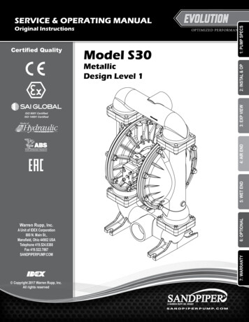
Literature Information(continued)Safety WarningsWARNINGOperation SectionTo avoid personal injury or death,carefully read and understand allinstructions before attempting tooperate any equipment or tools.Do not operate or work on a machine unlessyou read and understand the instructionsand warnings in this and all other applicablemanuals. Contact Dealer Service Tools forreplacement manuals. Proper care is yourresponsibility. Always follow all State andFederal health and safety laws and/or localregulations.The Operation section is a reference for thenew operator and a refresher for theexperienced operator.Photographs and illustrations guide theoperator through correct procedures for usingthe tool group.Operating techniques outlined in thispublication are basic. Skill and techniquesdevelop as the operator gains knowledge ofthe service tool and its capabilities.To avoid eye injury,always wear protectiveglasses or face shield.Make sure no one canbe injured by flying objects or debris whenusing tools or working on a component.Safety SectionSafety Icon NomenclaturePersonal ProtectionRead the manualClean up all leaked orspilled fluids immediately.Oil, fuel, or cleaning fluidleaked or spilled onto anyhot surfaces or electrical components cancause a fire, resulting in personal injury ordeath.Eye protectionFace protectionProhibited ActionPersonal injury can resultfrom slips or falls. DONOT leave tools orcomponentslayingaround the work area and clean up all spilledfluids immediately.No smokingHazard AvoidanceFire hazardPersonal injuriescan occur as aresult of usingpressurized air.Maximum air pressure at the nozzle must bebelow 205 kPa (30 psi) for cleaningpurposes.Wear protective clothing,protective glasses, and a protective faceshield when using pressure air.Pressurized airSlipping hazardTripping hazard4
NOTE: The 123-4940 Magnetic TimingIndicator Fixture replaced the original 9U-7308Magnetic Base, in order to adapt to an enginechange to large-diameter elephant's footrocker connections.General Information SectionIntroductionThe 223-2454 Tool Group is used to check andperform all on-engine fuel system adjustments,including injector synchronization, timing, andfuel setting (rack) on Caterpillar 3114, 3116,and 3126 Engines equipped with mechanicalunit injectors (MUI). The group also includestools to remove and install the unit injectorsand adjust the valves.New high-quality, deep offset, box wrenchesare also part of this group, making timingadjustment easier.Fuel SettingThe 128-8827 Fuel Setting Pin is an improvedversion of the 9U-7271 Pin; made easier to usein the very tight space that is available. Itworks on all versions of governors.The new group replaces the 1U-6680,9U-7305, and 128-8822 Tool Groups. The newtools are available individually to updateformer groups at a considerable cost savings,and offers the advantage of simplified toolingwhich provides more accurate adjustments inless time.The 130-2711 Holding Tool is used to hold thefuel setting pin against the governor housingface. It is a redesigned version of the older1U-6681 Holding Tool (part of the 1U-6680Tool Group), with modifications to make iteasier to insert and allow alternate handlelocations. The 130-2711 Holding Tool replacesthe 9U-7265 Clamp Assembly (part of9U-7305) which would not adapt to the later"Type V" version governor.Features of 223-2454 Tool GroupInjector SynchronizationThe new 128-9640 Injector SynchronizingFixture Group replaces the former 9U-7276Linkage Spring-Loading Tool and 9U-7275Support. The new fixture features aspring-loaded plunger which pushes directlyon the end of the number 1 injector rack head.It is used in conjunction with the 9U-7270Synchronizing Gauge Block (3.5 mm) or220-0123 Synchronizing Gauge Block(3.0 mm), which can be attached directly tothe fixture.Valve AdjustmentThe new double-ended (intake/exhaust)123-4941 Valve Setting Feeler Gauge hasspecial, short, offset 45 degree legs. Thisdesign greatly simplifies setting valves onnewer engines with a larger diameterelephant's foot, and works on any engine with0.38 mm (.015 in) intake and 0.64 mm (.025 in)exhaust valve lash.The 128-8823 Long Nose Locking Pliers isused to clamp directly to the control rod(in-between two rocker stands), and is used asa lever to actuate the control rod in the fuel-onand fuel-off directions. This ability to actuatethe rack in both directions is necessary forconsistent readings when using the newprocedure; the pliers replace the former9U-7264 Linkage Lever.New high-quality, deep offset, box wrenchesmake valve adjustments easier.Injector InstallationThe 1U-8013 (5 mm) Hex Bit Driver is includedto tighten the injector hold-down bolt whichhelps to reduce combustion gas leaks.TimingThe 123-4940 Magnetic Timing IndicatorFixture, used with the direct-reading 1U-8869Programmable Digital Position Indicator andassociated tooling, moves quickly from injectorto injector to make checking or adjusting thetiming quick and easy.5
Tooling NomenclatureThe tools shown in this chart are required to complete the synchronization and adjusting proceduresprovided in this manual and in the machine's Service Manual.Nomenclature for 223-2454 Tool GroupTools Required to Upgrade FormerGroupsItemPart No.DescriptionQty.9U-73051U-6680XXSynchronization Tooling1128-9640128-8706Injector Synchronization Fixture GroupSpring Plunger (serviceable part)129U-7270220-0123Sync Gauge Block, 3.5 mmSync Gauge Block, 3.0 mm1139U-5120Solenoid Spanner Wrench141U-8869Digital Position Indicator15128-8823Locking Long Nose Pliers, 150 mm (6.0 in) long161U-6675Spring Compressor678T-4177Bolt, Spring Compressor689U-72829U-6272Indicator Fixture GroupNylon Screw (serviceable part)198C-4984Bolt, Indicator Stand1109U-7263Contact Point [18.5 mm (.73 in) long]XXX1XXFuel Timing Tooling119U-7269Timing Gauge Block112123-49402Magnetic Base Group1X2XX13128-8824Deep Offset Wrench, 16 mm and 18 mm1RR14128-8825Deep Offset Wrench, 17 mm and 19 mm1RR159U-7274Contact Point, [85 mm (3.35 in) long]1Miscellaneous Engine Tools165P-03023Injector Removal Bar117123-49413Valve Setting Gauge (feeler gauge for adjusting valves)1XX18194-35423Hex Socket Bit Driver, 5 mm1RRRFuel Setting Tooling19130-2711Fuel Setting Holding Tool120136-4149Governor Connection Pliers121128-8827Fuel Setting Pin Assembly1221U-75233Pin Insert Pilot (use with 128-8827 Pin Assembly)1231U-7299Adjustment (FRC) Wrench (“Type V” 1994 and later Trucks)1XX241U-7300T-Handle Wrench, 3 mm hex (“Type V” 1994 and later Trucks)1XX251U-6673Injector Sync and FRC Adjust Wrench (all models,except “Type V” 1994 and later Trucks)1RRRRXX—6V-7145Case1—128-8828Foam Insert Group1—NEEG2688Decal—NEHS0610Tool Operating Manual1RXX Essential tools for new procedures.R Recommended or improved tools.2 Some of the former 9U-7305 Groups used the new 123-4940 Magnetic Base; check your specific tool group.3 Refer to the appropriate engine Service Manual for additional information on use of these tools.6X
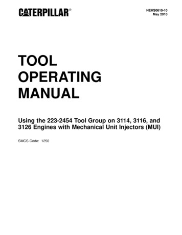
157648 in/mm2 219242023250610-04223-2454 Tool Group.Refer to the Nomenclature for 223-2454 Tool Group chart for item identification.7
Synchronizing injectors is accomplished in thisprocedure by placing the Sync Gauge Blockbetween the injector rack head pin and theinjector body of number 1 injector.Tool PlacementThe following illustration shows the placementof tools in the foam insert.12111, 24, 1023, 24NOTE: There is no adjustment screw in thecontrol linkage lever for number 1 injector,since it is the reference point for all the otherinjectors. Therefore, no synchronizingadjustment is made for the number 1 injector.5Always synchronize an injector after it hasbeen removed and reused/replaced. If thenumber 1 injector is reused or replaced,synchronization on ALL injectors must bechecked and adjusted.3Tooling and Equipment13, 1420 25 151716 18 21, 22196, 78, 9The tools sh
26.09.2010 · 6 1U-6675 Spring Compressor 6 7 8T-4177 Bolt, Spring Compressor 6 8 9U-7282 Indicator Fixture Group 1 9U-6272 Nylon Screw (serviceable part) 9 8C-4984 Bolt, Indicator Stand 1 10 9U-7263 Contact Point [18.5 mm (.73 in) long] 1 X Fuel Timing Tooling 11 9U-7269 Timing Gauge Block 1 X 12 123-4940 2Magnetic Base Group 1 X X 13 128-8824 Deep Offset Wrench, 16 mm and 18 mm 1 R